Operating Instructions
Page 4
...security card provided by BBE Sound, Inc. and are trademarks of a reflective material. ❑ See page 12 & 13 for replacement lamp. ENERGY STAR® is transported directly from SRS Labs, Inc. 2 BBE and BBE Symbol are trademarks or registered trademarks of BBE ...cover the windows that this case, please wait a few hours to direct illumination or direct sunlight. under "Service". SONY APPLIANCE MODEL NO: KDF-E55A20 KDF-E60A20 SONY TV STAND MODEL NO: SU-GW12 Replacement Parts See page 4 under U.S. Availability of digital cable television programming in a room...
...security card provided by BBE Sound, Inc. and are trademarks of a reflective material. ❑ See page 12 & 13 for replacement lamp. ENERGY STAR® is transported directly from SRS Labs, Inc. 2 BBE and BBE Symbol are trademarks or registered trademarks of BBE ...cover the windows that this case, please wait a few hours to direct illumination or direct sunlight. under "Service". SONY APPLIANCE MODEL NO: KDF-E55A20 KDF-E60A20 SONY TV STAND MODEL NO: SU-GW12 Replacement Parts See page 4 under U.S. Availability of digital cable television programming in a room...
Operating Instructions
Page 6
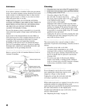
...-20) Grounding conductors (NEC section 810-21) Ground clamps Power service grounding electrode system (NEC Art 250 Part H) Cleaning ❑ Clean the rear cover area of the TV. To remove dust from the wall outlet and refer servicing to service the set . ❑ Clean the cabinet of the...parts. Service Damage Requiring Service Do not attempt to qualified service personnel. See "Replacing the Lamp" on the Screen Surface The screen surface has a special coating to clean the inside of the TV regularly. It should not be located in the vicinity of overhead power lines or other hazards....
...-20) Grounding conductors (NEC section 810-21) Ground clamps Power service grounding electrode system (NEC Art 250 Part H) Cleaning ❑ Clean the rear cover area of the TV. To remove dust from the wall outlet and refer servicing to service the set . ❑ Clean the cabinet of the...parts. Service Damage Requiring Service Do not attempt to qualified service personnel. See "Replacing the Lamp" on the Screen Surface The screen surface has a special coating to clean the inside of the TV regularly. It should not be located in the vicinity of overhead power lines or other hazards....
Operating Instructions
Page 7
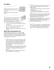
...sunlight or other than the specified manner and without the specified number of lamp. Do not expose the screen to follow the instructions mentioned below. ❑ Carry the TV with the specified number of the LCD projection TV. You may appear white due to drop it may drop and a ... when carrying it at least 4 inches (10 cm) from behind the screen. About the LCD projection TV Although the LCD projection TV is made with a new one (not supplied) when: • the lamp replacement indicator on the front panel blinks in red, • screen images become dark, • no image...
...sunlight or other than the specified manner and without the specified number of lamp. Do not expose the screen to follow the instructions mentioned below. ❑ Carry the TV with the specified number of the LCD projection TV. You may appear white due to drop it may drop and a ... when carrying it at least 4 inches (10 cm) from behind the screen. About the LCD projection TV Although the LCD projection TV is made with a new one (not supplied) when: • the lamp replacement indicator on the front panel blinks in red, • screen images become dark, • no image...
Operating Instructions
Page 8
...Sony TV Presenting the Sony TV 8 Package Contents 8 Features 8 Enjoying Your TV 10 Notes on the TV 10 Screen 10 Indicators 11 Projection Lamp 11 Installing the TV 12 Carrying Your TV 12 Take Precaution during Installation 13 To Prevent the TV from Falling 13 When Installing Your TV Against a Wall .....13 Recommended Viewing Area 13 TV... Overview 56 Accessing the Video Settings 58 Selecting Video Options 58 Accessing the Audio Settings 60 Selecting Audio Options 60 Accessing the Screen Settings 62 Selecting Screen Options 62 Accessing the Channel Settings 64 Selecting ...
...Sony TV Presenting the Sony TV 8 Package Contents 8 Features 8 Enjoying Your TV 10 Notes on the TV 10 Screen 10 Indicators 11 Projection Lamp 11 Installing the TV 12 Carrying Your TV 12 Take Precaution during Installation 13 To Prevent the TV from Falling 13 When Installing Your TV Against a Wall .....13 Recommended Viewing Area 13 TV... Overview 56 Accessing the Video Settings 58 Selecting Video Options 58 Accessing the Audio Settings 60 Selecting Audio Options 60 Accessing the Screen Settings 62 Selecting Screen Options 62 Accessing the Channel Settings 64 Selecting ...
Operating Instructions
Page 9
Accessing the Setup Settings 70 Selecting Setup Options 70 Programming Caption Vision 72 Accessing the Applications Settings 73 Selecting Applications Options 73 Other Information Overview 75 Contacting Sony 75 Replacing the Lamp 76 How to Replace the Lamp 76 Troubleshooting 80 Remote Control 80 CableCARDTM Device 80 Video 81 Audio 82 Channels 82 General 83 Specifications 84 Optional Accessories 85 Index Index 87 7
Accessing the Setup Settings 70 Selecting Setup Options 70 Programming Caption Vision 72 Accessing the Applications Settings 73 Selecting Applications Options 73 Other Information Overview 75 Contacting Sony 75 Replacing the Lamp 76 How to Replace the Lamp 76 Troubleshooting 80 Remote Control 80 CableCARDTM Device 80 Video 81 Audio 82 Channels 82 General 83 Specifications 84 Optional Accessories 85 Index Index 87 7
Operating Instructions
Page 13
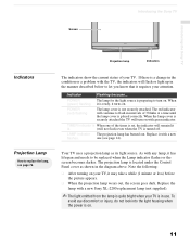
... becomes darker. Note the following: ❑ After turning on with the TV, the indicators will continue to turn on your TV. Introducing the Sony TV Introducing the Sony TV Screen Projection lamp POWER LAMP TIMER POWER Indicators Indicators Projection Lamp How to replace the lamp, see page 14). POWER The lamp for the light source is located under the Control Panel cover as...
... becomes darker. Note the following: ❑ After turning on with the TV, the indicators will continue to turn on your TV. Introducing the Sony TV Introducing the Sony TV Screen Projection lamp POWER LAMP TIMER POWER Indicators Indicators Projection Lamp How to replace the lamp, see page 14). POWER The lamp for the light source is located under the Control Panel cover as...
Operating Instructions
Page 16
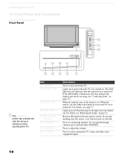
...this may be affected. Do not put anything near the sensor, as a reference when operating the TV. For details, see "Replacing the Lamp" on /off the TV. For details, see "Contacting Sony" on . When the timer is turned on page 75). Use the dot as its function may...not light up when the main power is turned off . Press to turn on page 76. Introducing the Sony TV TV Front Panel and Connectors Front Panel POWER LAMP TIMER POWER POWER LAMP TIMER POWER CHANNEL 3 # VOLUME 3 # TV/VIDEO 6 7 8 5432 1 z The CHANNEL + button has a tactile dot. Receives IR signals from...
...this may be affected. Do not put anything near the sensor, as a reference when operating the TV. For details, see "Replacing the Lamp" on /off the TV. For details, see "Contacting Sony" on . When the timer is turned on page 75). Use the dot as its function may...not light up when the main power is turned off . Press to turn on page 76. Introducing the Sony TV TV Front Panel and Connectors Front Panel POWER LAMP TIMER POWER POWER LAMP TIMER POWER CHANNEL 3 # VOLUME 3 # TV/VIDEO 6 7 8 5432 1 z The CHANNEL + button has a tactile dot. Receives IR signals from...
Operating Instructions
Page 17
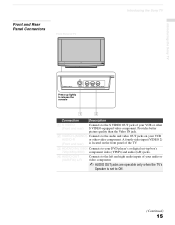
... located on your VCR or other video component. Introducing the Sony TV Front and Rear Panel Connectors Front Panel of your VCR AUDIO-R or other S VIDEO-equipped video component. Provides better picture quality than the Video IN jack. 2 VIDEO/ ... and right audio inputs of your audio or video component. ✍ AUDIO OUT jacks are operable only when the TV's Speaker is set to the S VIDEO OUT jack of TV Introducing the Sony TV POWER LAMP TIMER POWER VIDEO 2 INPUT S VIDEO VIDEO L (MONO) R AUDIO Press up lightly to release the console 1 2 Connection Description 1 S VIDEO...
... located on your VCR or other video component. Introducing the Sony TV Front and Rear Panel Connectors Front Panel of your VCR AUDIO-R or other S VIDEO-equipped video component. Provides better picture quality than the Video IN jack. 2 VIDEO/ ... and right audio inputs of your audio or video component. ✍ AUDIO OUT jacks are operable only when the TV's Speaker is set to the S VIDEO OUT jack of TV Introducing the Sony TV POWER LAMP TIMER POWER VIDEO 2 INPUT S VIDEO VIDEO L (MONO) R AUDIO Press up lightly to release the console 1 2 Connection Description 1 S VIDEO...
Operating Instructions
Page 77
... the Lamp Troubleshooting Specifications Optional Accessories Index Page 75 76 80 84 85 87 Contacting Sony If, after reading these operating instructions, you have additional questions related to the use of your Sony television, please call our Customer Information Services Center. For US residents: 1-800-222-SONY (7669) or visit: http://www.sonystyle.com/tv...
... the Lamp Troubleshooting Specifications Optional Accessories Index Page 75 76 80 84 85 87 Contacting Sony If, after reading these operating instructions, you have additional questions related to the use of your Sony television, please call our Customer Information Services Center. For US residents: 1-800-222-SONY (7669) or visit: http://www.sonystyle.com/tv...
Operating Instructions
Page 78
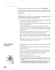
Other Information Replacing the Lamp The projection lamp, which illuminates the picture, has a limited life. See page 79. How to Replace the Lamp 1 Turn off .) 2 Wait at least 30 minutes after removing the lamp. Wait several minutes, then unplug the power cord. (The cooling fan will continue to ... Use a Sony XL-2200 replacement lamp (not supplied) for proper disposal of the box. Use of any purpose other lamp may cause injury or fire. ❑ Do not put flammable materials and metal objects inside the lamp receptacle of the TV flashes, it is designed to replace the lamp with a...
Other Information Replacing the Lamp The projection lamp, which illuminates the picture, has a limited life. See page 79. How to Replace the Lamp 1 Turn off .) 2 Wait at least 30 minutes after removing the lamp. Wait several minutes, then unplug the power cord. (The cooling fan will continue to ... Use a Sony XL-2200 replacement lamp (not supplied) for proper disposal of the box. Use of any purpose other lamp may cause injury or fire. ❑ Do not put flammable materials and metal objects inside the lamp receptacle of the TV flashes, it is designed to replace the lamp with a...
Operating Instructions
Page 79
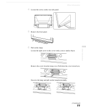
Pull down the cover toward you. Unscrew the lamp and pull out the lamp horizontally. Other Information 5 Remove the front panel. Remove the screw from the lamp cover. Loosen the right screw on the rear side panel. Other Information (Continued) 77 4 Loosen the screws on the cover with a coin or similar object. STD/DUO PRO POWER 6 Pull out the lamp.
Pull down the cover toward you. Unscrew the lamp and pull out the lamp horizontally. Other Information 5 Remove the front panel. Remove the screw from the lamp cover. Loosen the right screw on the rear side panel. Other Information (Continued) 77 4 Loosen the screws on the cover with a coin or similar object. STD/DUO PRO POWER 6 Pull out the lamp.
Operating Instructions
Page 80
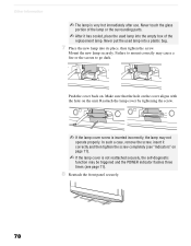
... the surrounding parts. ✍ After it correctly and then tighten the screw completely (see "Indicators" on page 11). ✍ If the lamp cover is not reattached securely, the self-diagnostic function may be triggered and the POWER indicator flashes three times (see page 11). 8 Reattach the front ...panel securely. Never touch the glass portion of the replacement lamp. STD/DUO PRO POWER 78 Failure to mount correctly may cause a fire or the screen to go dark. Reattach the...
... the surrounding parts. ✍ After it correctly and then tighten the screw completely (see "Indicators" on page 11). ✍ If the lamp cover is not reattached securely, the self-diagnostic function may be triggered and the POWER indicator flashes three times (see page 11). 8 Reattach the front ...panel securely. Never touch the glass portion of the replacement lamp. STD/DUO PRO POWER 78 Failure to mount correctly may cause a fire or the screen to go dark. Reattach the...
Operating Instructions
Page 81
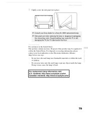
.... For disposal or recycling information, please contact your Sony dealer for a Sony XL-2200 replacement lamp. ✍ Take great care when replacing the lamp or plugging in the United States. residents: http://www.sonystyle.com/tv/ Canadian residents: http://www.sonystyle.ca/tv/ Other Information 79 For replacement lamp information visit: U.S. Disposal of children. ❑ Do not...
.... For disposal or recycling information, please contact your Sony dealer for a Sony XL-2200 replacement lamp. ✍ Take great care when replacing the lamp or plugging in the United States. residents: http://www.sonystyle.com/tv/ Canadian residents: http://www.sonystyle.ca/tv/ Other Information 79 For replacement lamp information visit: U.S. Disposal of children. ❑ Do not...
Operating Instructions
Page 85
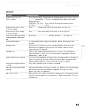
...Label Video Inputs option is not set ❏ The LED will clear all of the lamp cover may indicate the TV needs service. it completely (see page 70). If the LED (red) blinks continuously,... ❏ Select RESET menu option while in the Video menu (see page 60). TV cabinet creaks ❏ When the TV is in use a special bi-directional splitter that the menu option is designed... for both KDF-E55A20 and KDF-E60A20). To rest the timer or cancel the timer, see page 66), enter the following master password: 4357. WARNING: The Factory Reset will remain lit even when the TV is not...
...Label Video Inputs option is not set ❏ The LED will clear all of the lamp cover may indicate the TV needs service. it completely (see page 70). If the LED (red) blinks continuously,... ❏ Select RESET menu option while in the Video menu (see page 60). TV cabinet creaks ❏ When the TV is in use a special bi-directional splitter that the menu option is designed... for both KDF-E55A20 and KDF-E60A20). To rest the timer or cancel the timer, see page 66), enter the following master password: 4357. WARNING: The Factory Reset will remain lit even when the TV is not...
Operating Instructions
Page 86
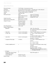
...Rectangular (1) PCMCIA Type I/II 12 W (L), 12 W (R) 84 Other Information Specifications Projection System LCD Panel Projection Lens Antenna Lamp Television System Visible Screen Size (Picture measured diagonally) Channel Coverage Power Requirements Number of ...projection system 0.87 inch TFT LCD panel Approx. 3.28 million dots (1,042,168 pixels) High Performance, large diameter hybrid lens F2.4 75 ohm external terminal for VHF/UHF 132W, XL-2200 NTSC American TV Standard ATSC (8VSB terrestrial) ATSC compliant 8VSB QAM on cable ANSI/SCTE 07 2000 KDF-E55A20: 55 inches KDF-E60A20: 60...
...Rectangular (1) PCMCIA Type I/II 12 W (L), 12 W (R) 84 Other Information Specifications Projection System LCD Panel Projection Lens Antenna Lamp Television System Visible Screen Size (Picture measured diagonally) Channel Coverage Power Requirements Number of ...projection system 0.87 inch TFT LCD panel Approx. 3.28 million dots (1,042,168 pixels) High Performance, large diameter hybrid lens F2.4 75 ohm external terminal for VHF/UHF 132W, XL-2200 NTSC American TV Standard ATSC (8VSB terrestrial) ATSC compliant 8VSB QAM on cable ANSI/SCTE 07 2000 KDF-E55A20: 55 inches KDF-E60A20: 60...

Operating Instructions
Page 87
...inches) (1,456 × 943 × 491 mm) KDF-E60A20: (62 × 39 5/8 × 20 1/2 inches) (1,574 × 1,005 × 518 mm) Mass KDF-E55A20: 92.5 lb (42 kg) KDF-E60A20: 101.5 lb (46.1 kg) Supplied Accessories Remote ...Control RM-YD002 AA (R6) Batteries 2 supplied for remote control Design and specifications are approximate. Optional Accessories ❑ HDMI cable ❑ Component video cable ❑ S VIDEO cable ❑ A/V cable ❑ Audio cable ❑ Optical cable ❑ TV Stand: SU-GW12 ❑ Lamp...
...inches) (1,456 × 943 × 491 mm) KDF-E60A20: (62 × 39 5/8 × 20 1/2 inches) (1,574 × 1,005 × 518 mm) Mass KDF-E55A20: 92.5 lb (42 kg) KDF-E60A20: 101.5 lb (46.1 kg) Supplied Accessories Remote ...Control RM-YD002 AA (R6) Batteries 2 supplied for remote control Design and specifications are approximate. Optional Accessories ❑ HDMI cable ❑ Component video cable ❑ S VIDEO cable ❑ A/V cable ❑ Audio cable ❑ Optical cable ❑ TV Stand: SU-GW12 ❑ Lamp...
Operating Instructions
Page 89
... Video 59 Alternate Audio 49 Alternate Video 49 ANT button 42 Applications Menu 73 Audio Menu 60 Audio receiver, connecting 39 Audio setting 56 B Balance, adjusting 60 Bass, adjusting 60 Batteries, inserting in remote 41 Bilingual audio 61 Brightness, adjusting 58 C Cable with VCR, connecting 32 Cable box connecting ... GUIDE button 42, 48 Guide menu 49 H Hue, adjusting 58 I Inputs, labeling 70 Installation of the projection TV 19-39 J JUMP button 42, 51 L Label Channels 30, 65 video inputs 70 Lamp, replacing 76-79 M MENU button 43 Menus Parent 66 Screen 62 Setup 70 Mode Custom 58 Standard 58...
... Video 59 Alternate Audio 49 Alternate Video 49 ANT button 42 Applications Menu 73 Audio Menu 60 Audio receiver, connecting 39 Audio setting 56 B Balance, adjusting 60 Bass, adjusting 60 Batteries, inserting in remote 41 Bilingual audio 61 Brightness, adjusting 58 C Cable with VCR, connecting 32 Cable box connecting ... GUIDE button 42, 48 Guide menu 49 H Hue, adjusting 58 I Inputs, labeling 70 Installation of the projection TV 19-39 J JUMP button 42, 51 L Label Channels 30, 65 video inputs 70 Lamp, replacing 76-79 M MENU button 43 Menus Parent 66 Screen 62 Setup 70 Mode Custom 58 Standard 58...


