
MX-2300N | MX-2700N | MX-3500N | MX-3501N | MX-4500N | MX-4501N Operation Manual Suite
Page 782
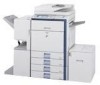
AUTOMATIC DOCUMENT FEEDER (1) (2) (3) (4) (5) (6) (7) (9) (8) MX-3501N/4501N (2) (3) (4) (5) (1) Paper feed roller This roller rotates to automatically feed the original. (2) Document feeding area cover Open this cover to remove an original misfeed or clean the paper feed roller. (3) Original guides These help ensure that the original is temporarily output to this tray in order to scan a book or other thick...
AUTOMATIC DOCUMENT FEEDER (1) (2) (3) (4) (5) (6) (7) (9) (8) MX-3501N/4501N (2) (3) (4) (5) (1) Paper feed roller This roller rotates to automatically feed the original. (2) Document feeding area cover Open this cover to remove an original misfeed or clean the paper feed roller. (3) Original guides These help ensure that the original is temporarily output to this tray in order to scan a book or other thick...

MX-2300N | MX-2700N | MX-3500N | MX-3501N | MX-4500N | MX-4501N Operation Manual Suite
Page 821
... the staple cartridge runs out of the arrow to move the staple unit out to the front. Turn the roller rotating knob as shown until it stops. 2 3 Roller rotating knob A Staple unit 4 Turn roller rotating knob A in the direction of staples, a message will appear in the operation panel. Press the lock button to... until the stapler section until the triangle mark is aligned with the indicator. Follow the procedure below to release the staple case cover and then remove the staple cartridge. 5 When staples remain, the staple cartridge cannot be...
... the staple cartridge runs out of the arrow to move the staple unit out to the front. Turn the roller rotating knob as shown until it stops. 2 3 Roller rotating knob A Staple unit 4 Turn roller rotating knob A in the direction of staples, a message will appear in the operation panel. Press the lock button to... until the stapler section until the triangle mark is aligned with the indicator. Follow the procedure below to release the staple case cover and then remove the staple cartridge. 5 When staples remain, the staple cartridge cannot be...

MX-2300N | MX-2700N | MX-3500N | MX-3501N | MX-4500N | MX-4501N Operation Manual Suite
Page 823
Removing staple jams Follow the steps below to remove a staple jam. 1 While pulling the lever, slide the saddle stitch finisher to tear the paper during removal. Open the front cover. 2 Turn roller rotating knob B as shown until the blue indicator is visible. 3 Blue Roller rotating knob B Remove any paper from the stapler compiler. 4 Be careful not to the left until it stops. If the saddle stitch function was being used, open the saddle stitch section 5 cover. 48
Removing staple jams Follow the steps below to remove a staple jam. 1 While pulling the lever, slide the saddle stitch finisher to tear the paper during removal. Open the front cover. 2 Turn roller rotating knob B as shown until the blue indicator is visible. 3 Blue Roller rotating knob B Remove any paper from the stapler compiler. 4 Be careful not to the left until it stops. If the saddle stitch function was being used, open the saddle stitch section 5 cover. 48

MX-2300N | MX-2700N | MX-3500N | MX-3501N | MX-4500N | MX-4501N Operation Manual Suite
Page 824
.... Be careful not to the front. Turn the roller rotating knob until it is aligned with the indicator. Remove the staple case. Remove the leading staple if it stops. 8 9 Roller rotating knob A Staple unit 10 Turn roller rotating knob A in the direction of the staple case and remove the jammed 11 staple. If bent staples remain...
.... Be careful not to the front. Turn the roller rotating knob until it is aligned with the indicator. Remove the staple case. Remove the leading staple if it stops. 8 9 Roller rotating knob A Staple unit 10 Turn roller rotating knob A in the direction of the staple case and remove the jammed 11 staple. If bent staples remain...

Installation Manual
Page 7
...the DV lock lever, and release the fixing screw. (1 position for one month or more, the heat roller rubber may be deformed. MX-3500N/4500N, MX-3501N/4501N 1 - 4 Primary transfer and transfer belt protection sheet disassembly/cleaning roller pressing 1) Open the front cover. C. A B 2) Lower the ...case, release the pressure by pushing up both levers. 4) Pinch the knob and remove the development unit. Fusing heat roller pressing (F/R) 1) Open the right door. 2 1 2) Check that it is left unused for each color) 1 2 NOTE: If the machine is fit as shown in (A). (2) Scanner ...
...the DV lock lever, and release the fixing screw. (1 position for one month or more, the heat roller rubber may be deformed. MX-3500N/4500N, MX-3501N/4501N 1 - 4 Primary transfer and transfer belt protection sheet disassembly/cleaning roller pressing 1) Open the front cover. C. A B 2) Lower the ...case, release the pressure by pushing up both levers. 4) Pinch the knob and remove the development unit. Fusing heat roller pressing (F/R) 1) Open the right door. 2 1 2) Check that it is left unused for each color) 1 2 NOTE: If the machine is fit as shown in (A). (2) Scanner ...

Installation Manual
Page 8
... the intermediate transfer belt may disperse when removing from the bag. 4 : Nov. 15 2006 5) Loosen the blue screw. 4 D. Check to insure that the lock is of fine powder, it from the driving roller. Driving roller 15cm MX-3500N/4500N, MX-3501N/4501N 1 - 5 B A * Since ...titanium hydroxide is released as shown with its backside facing upward and remove the cleaner frame UN. 7) Remove the transfer belt protect sheet horizontally in the arrow direction...
... the intermediate transfer belt may disperse when removing from the bag. 4 : Nov. 15 2006 5) Loosen the blue screw. 4 D. Check to insure that the lock is of fine powder, it from the driving roller. Driving roller 15cm MX-3500N/4500N, MX-3501N/4501N 1 - 5 B A * Since ...titanium hydroxide is released as shown with its backside facing upward and remove the cleaner frame UN. 7) Remove the transfer belt protect sheet horizontally in the arrow direction...

Installation Manual
Page 23
Removal of the exit roller unit 1) Open the right door. 2 1 2) Remove the screw, and remove the connector cover. Installation of the exit tray unit S2)erOvpiecnetheMfraonntucaablinet. OFF 3) Remove the earth cord and disconnect the power plug of the main unit. B. Turn off the power of...up or blink. Packed part names 1 Exit roller unit 2 Full detection actuator Quantity 1 1 2. Turn OFF the power switch in the package. 1 2 No. Check the packed items 1) Check that the data lamp on the operation panel. OFF OFF MX3500N MX-TRX2 3 - 1 Installation * Before starting ...
Removal of the exit roller unit 1) Open the right door. 2 1 2) Remove the screw, and remove the connector cover. Installation of the exit tray unit S2)erOvpiecnetheMfraonntucaablinet. OFF 3) Remove the earth cord and disconnect the power plug of the main unit. B. Turn off the power of...up or blink. Packed part names 1 Exit roller unit 2 Full detection actuator Quantity 1 1 2. Turn OFF the power switch in the package. 1 2 No. Check the packed items 1) Check that the data lamp on the operation panel. OFF OFF MX3500N MX-TRX2 3 - 1 Installation * Before starting ...

Installation Manual
Page 24
Use the screw which was removed in the rear side, and remove the paper exit cover. 4 1 2 C. ON 5) Install the connector cover, and fix it with the screw. 3) Turn ON the ...cord, and insert the power plug of the main unit into the power outlet. 3 4) Connect the connector, and install the exit roller unit (package part No. 1). B B A MX3500N MX-TRX2 3 - 2 D. Disengage the engagement in the front side then in step 3) and fix the unit. 2) Open the front... direction of the main unit. Tray setting Use SIM26-1 to set the tray YES/NO. Turn on the operation panel. 3) Remove the screw.
Use the screw which was removed in the rear side, and remove the paper exit cover. 4 1 2 C. ON 5) Install the connector cover, and fix it with the screw. 3) Turn ON the ...cord, and insert the power plug of the main unit into the power outlet. 3 4) Connect the connector, and install the exit roller unit (package part No. 1). B B A MX3500N MX-TRX2 3 - 2 D. Disengage the engagement in the front side then in step 3) and fix the unit. 2) Open the front... direction of the main unit. Tray setting Use SIM26-1 to set the tray YES/NO. Turn on the operation panel. 3) Remove the screw.

Installation Manual
Page 36
... rail with the fixing screw (package part No. 8). * Fix the side plate of the paper exit shifter with one fixing screw (package part No. 8). 3) Disengage two pawls, and remove the paper exit tray cover. 8) Install the front slide rail (A) (package part No. 2) with the three fixing...left front cover (B) (package part No. 6) with the fixing guide. MX3500N MX-FNX1 5 - 3 A 4) Remove four screws, and remove the paper exit tray. * When removing the paper exit tray, there is no need to insure that the slide roller is in the rail groove, and insert the inner finisher. 6) Engage the projection...
... rail with the fixing screw (package part No. 8). * Fix the side plate of the paper exit shifter with one fixing screw (package part No. 8). 3) Disengage two pawls, and remove the paper exit tray cover. 8) Install the front slide rail (A) (package part No. 2) with the three fixing...left front cover (B) (package part No. 6) with the fixing guide. MX3500N MX-FNX1 5 - 3 A 4) Remove four screws, and remove the paper exit tray. * When removing the paper exit tray, there is no need to insure that the slide roller is in the rail groove, and insert the inner finisher. 6) Engage the projection...

Installation Manual
Page 47
...frame with two fixing screws A (package part No. 5). 2) Install the rail bracket to install. 2) As shown in the figure, rotate the roller rotation knob so that there are no clearance at the left and right sections of the staple cartridge. 4) Insert the staple unit and close the... front cover of the Operation Manual pocket. MX3500N MX-RBX1, MX-FNX2 7 - 5 2) Install the Operation Manual storage cover (which was removed from the machine) to confirm that the triangle mark is fit with the indication. C. First, insert the pawl...
...frame with two fixing screws A (package part No. 5). 2) Install the rail bracket to install. 2) As shown in the figure, rotate the roller rotation knob so that there are no clearance at the left and right sections of the staple cartridge. 4) Insert the staple unit and close the... front cover of the Operation Manual pocket. MX3500N MX-RBX1, MX-FNX2 7 - 5 2) Install the Operation Manual storage cover (which was removed from the machine) to confirm that the triangle mark is fit with the indication. C. First, insert the pawl...


