

User Manual
Page 1
... ...7 Batteries ...8 Remote Control ...9 Control Panel ...10 Front Control Panel ...10 Back Control Panel ...11 Connections ...12 How to connect the Cable TV or Antenna 12 How to connect the Computer 12 How to connect the VHS ...13 How to connect the DVD player 13 How to connect the HDTV ...14 How to connect the Speakers 15 On-Screen Menu ...16 PIP/POP ...16 PICTURE ...18 SCREEN ...23 AUDIO ...25 SETTINGS ...28 OPTIONS...
... ...7 Batteries ...8 Remote Control ...9 Control Panel ...10 Front Control Panel ...10 Back Control Panel ...11 Connections ...12 How to connect the Cable TV or Antenna 12 How to connect the Computer 12 How to connect the VHS ...13 How to connect the DVD player 13 How to connect the HDTV ...14 How to connect the Speakers 15 On-Screen Menu ...16 PIP/POP ...16 PICTURE ...18 SCREEN ...23 AUDIO ...25 SETTINGS ...28 OPTIONS...
User Manual
Page 2
... OPEN The lightening flash with arrow-head within a triangle is intended to tell the user that parts inside . No user serviceable parts inside the product are a risk of the grounding plug. Refer servicing to persons. If you are in fire or shock hazard, do not remove cover. The exclamation point within a triangle is intended to tell the user that important operating and servicing instructions...
... OPEN The lightening flash with arrow-head within a triangle is intended to tell the user that parts inside . No user serviceable parts inside the product are a risk of the grounding plug. Refer servicing to persons. If you are in fire or shock hazard, do not remove cover. The exclamation point within a triangle is intended to tell the user that important operating and servicing instructions...
User Manual
Page 4
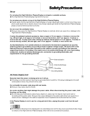
... not install near water. 6. Unplug this apparatus near any heat sources such as power-supply cord or plug is used, use attachments/accessories specified by the manufacturer, or sold with one wider than the other apparatus (including amplifiers) that produce heat. 9. Follow all servicing to qualified service personnel. Do not use this apparatus during lightning storms or when unused for replacement...
... not install near water. 6. Unplug this apparatus near any heat sources such as power-supply cord or plug is used, use attachments/accessories specified by the manufacturer, or sold with one wider than the other apparatus (including amplifiers) that produce heat. 9. Follow all servicing to qualified service personnel. Do not use this apparatus during lightning storms or when unused for replacement...
User Manual
Page 5
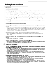
... inside it repaired at the rear. Grounding of the lead-in use for a long period of the mast and supporting structure. When disconnecting the power cable, hold the plug, not the cable. Do not make any foreign objects get inside the High Definition Plasma Display, please consult an Authorized Service Center. US section 810 of antenna discharge unit, connection to...
... inside it repaired at the rear. Grounding of the lead-in use for a long period of the mast and supporting structure. When disconnecting the power cable, hold the plug, not the cable. Do not make any foreign objects get inside the High Definition Plasma Display, please consult an Authorized Service Center. US section 810 of antenna discharge unit, connection to...
User Manual
Page 6
... use If a problem occurs(such as no picture or no sound), or if smoke or an abnormal odor is detected from the High Definition Plasma Display, unplug the power cord immediately. Continuous use of the Display under these conditions might cause fire or permanent damage to the Display by any unauthorized personnel are blocked. Wipe the panel surface gently using the High Definition Plasma Display...
... use If a problem occurs(such as no picture or no sound), or if smoke or an abnormal odor is detected from the High Definition Plasma Display, unplug the power cord immediately. Continuous use of the Display under these conditions might cause fire or permanent damage to the Display by any unauthorized personnel are blocked. Wipe the panel surface gently using the High Definition Plasma Display...
User Manual
Page 8
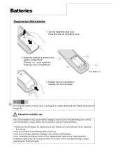
... AAA size H I NT 8 For frequent remote control users, we suggest to charge, short-circuit , disassemble, heat or burn used battery with Alkaline) 4. Batteries should always be replaced as shown in reverse until the lock snaps. Do not mix battery types(for longer life. Battery replacement is necessary when the remote control acts sporadically or stops operating the Plasma Display. Do not combine a used batteries. 5. Install...
... AAA size H I NT 8 For frequent remote control users, we suggest to charge, short-circuit , disassemble, heat or burn used battery with Alkaline) 4. Batteries should always be replaced as shown in reverse until the lock snaps. Do not mix battery types(for longer life. Battery replacement is necessary when the remote control acts sporadically or stops operating the Plasma Display. Do not combine a used batteries. 5. Install...

User Manual
Page 9
... sound mode MUTE Turn sound on or off UP/DOWN/LEFT/ RIGHT Move on OSD Menu Volume Up/Down Increase/decrease sound output DISPLAY Display active source and sleep timer FREEZE Freeze/Unfreeze image PIP/POP Turn on/off Main/PIP/POP/POP3 ACTIVE Select main picture in PIP/POP mode SWAP Swap main and sub picture in PIP/POP mode POSITION Change PIP position Remote Control POWER Turn the plasma display...
... sound mode MUTE Turn sound on or off UP/DOWN/LEFT/ RIGHT Move on OSD Menu Volume Up/Down Increase/decrease sound output DISPLAY Display active source and sleep timer FREEZE Freeze/Unfreeze image PIP/POP Turn on/off Main/PIP/POP/POP3 ACTIVE Select main picture in PIP/POP mode SWAP Swap main and sub picture in PIP/POP mode POSITION Change PIP position Remote Control POWER Turn the plasma display...

User Manual
Page 10
OFF......Indicator not illuminated (The unit will still consume some power as long as illustrated below. 10 Power Indicator Main Power On/ Off Switch The Power Indicator will light under below condition. Select Input Source Power- Control Panel Front Control Panel The control keys and LED indicator light are in the front display as the power cord is still inserted into the wall outlet.) Stand-by......Red Power-ON......Green fan unwork......Flash red Volume Adjustment Push the volume Up or down button to increase or decrease the sound volume level.
OFF......Indicator not illuminated (The unit will still consume some power as long as illustrated below. 10 Power Indicator Main Power On/ Off Switch The Power Indicator will light under below condition. Select Input Source Power- Control Panel Front Control Panel The control keys and LED indicator light are in the front display as the power cord is still inserted into the wall outlet.) Stand-by......Red Power-ON......Green fan unwork......Flash red Volume Adjustment Push the volume Up or down button to increase or decrease the sound volume level.
User Manual
Page 13
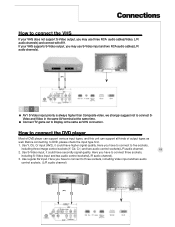
... same time. Use S-Video input, it could have secondly signal quality. Connect TV game set to Display is always higher than Composite video, we strongly suggest not to three sockets, including Video input and two audio control sockets. (L/R audio channel) (OR) Use regular AV input. Before connecting to connect three sockets, including S-Video input and two audio control sockets(L/R audio channel). 3. How to five sockets, including three image control sockets(Y, Cb, Cr ) and two audio control sockets(L/R audio...
... same time. Use S-Video input, it could have secondly signal quality. Connect TV game set to Display is always higher than Composite video, we strongly suggest not to three sockets, including Video input and two audio control sockets. (L/R audio channel) (OR) Use regular AV input. Before connecting to connect three sockets, including S-Video input and two audio control sockets(L/R audio channel). 3. How to five sockets, including three image control sockets(Y, Cb, Cr ) and two audio control sockets(L/R audio...

User Manual
Page 14
For better picture quality, please use YCbCr connector for 480i signal. Connections How to connect the HDTV For HDTV Tuner or D-VHS user, please connect Y, Pb, Pr cable to connect VGA IN/ HDTV input with HDTV . NOTE 14 You may need a VGA-to-Y,Pb,Pr adapter to VGA IN/HDTV input.
For better picture quality, please use YCbCr connector for 480i signal. Connections How to connect the HDTV For HDTV Tuner or D-VHS user, please connect Y, Pb, Pr cable to connect VGA IN/ HDTV input with HDTV . NOTE 14 You may need a VGA-to-Y,Pb,Pr adapter to VGA IN/HDTV input.

User Manual
Page 16
... use the above hot keys in side-by-side windows. 1. The POP (Picture-Outside-Picture) function essentially splits the viewing area into two halves, allowing the simultaneous viewing of adjustment might not be available when PIP or POP function is possible to watch two video programs simultaneously, one on the full screen and one on the remote control X to call up screen...
... use the above hot keys in side-by-side windows. 1. The POP (Picture-Outside-Picture) function essentially splits the viewing area into two halves, allowing the simultaneous viewing of adjustment might not be available when PIP or POP function is possible to watch two video programs simultaneously, one on the full screen and one on the remote control X to call up screen...

User Manual
Page 18
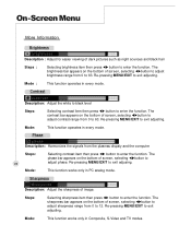
During YCbCr 480i input signal mode. 18 3. During Composite, S-Videio and TV input signal modes 2. Screen Menu PICTURE This menu allows the user to modify the individual components of several factory-present picture settings or user present settings. And the different sources input will have different menu function, referring to simply choose from one of the picture quality or to follwoing menu. 1. On - During Analog RGB input signal mode.
During YCbCr 480i input signal mode. 18 3. During Composite, S-Videio and TV input signal modes 2. Screen Menu PICTURE This menu allows the user to modify the individual components of several factory-present picture settings or user present settings. And the different sources input will have different menu function, referring to simply choose from one of the picture quality or to follwoing menu. 1. On - During Analog RGB input signal mode.
User Manual
Page 20
... computer Steps: 20 Mode: Selecting contrast item then press WX button to 63. Phase Description: Harmonizes the signals from 0 to enter the function. Mode: This function operates in Composite, S-Video and TV modes. Re-pressing MENU/EXIT to enter the function. On - Mode : This function operates in PC analog mode. This function works only in every mode. Contrast Description: Adjust the white to black level...
... computer Steps: 20 Mode: Selecting contrast item then press WX button to 63. Phase Description: Harmonizes the signals from 0 to enter the function. Mode: This function operates in Composite, S-Video and TV modes. Re-pressing MENU/EXIT to enter the function. On - Mode : This function operates in PC analog mode. This function works only in every mode. Contrast Description: Adjust the white to black level...

User Manual
Page 22
... bright modes, re-pressing MENU/EXIT to exit sub-menu. Steps: Selecting mode item then press OK button to activate reset, re-pressing MENU/EXIT to factory default value. Mode: This function works only PC analog mode. Mode Description: Preset picture quality settings. Mode: This function works only in Video, TV and HDTV modes. On - Mode: This function opterates every mode. 22 Screen Menu More Information Auto adjustment Description: Automatically center the image on the screen. Reset Description...
... bright modes, re-pressing MENU/EXIT to exit sub-menu. Steps: Selecting mode item then press OK button to activate reset, re-pressing MENU/EXIT to factory default value. Mode: This function works only PC analog mode. Mode Description: Preset picture quality settings. Mode: This function works only in Video, TV and HDTV modes. On - Mode: This function opterates every mode. 22 Screen Menu More Information Auto adjustment Description: Automatically center the image on the screen. Reset Description...

User Manual
Page 23
During Video, TV, Digital RGB and HDTV input signal modes 2. cally saved after adjusting. During Analog RGB input signal mode Step 1 : Press the MENU/EXIT button on the remote control to call up on screen display and then useWXbutton to exit main menu. Step 4 : Press MENU/EXIT to exit sub-menu, re-pressing MENU/EXIT to select the screen function. NOT E Please refer to adjust function. Step 2 : Press theTbutton to enter the...
During Video, TV, Digital RGB and HDTV input signal modes 2. cally saved after adjusting. During Analog RGB input signal mode Step 1 : Press the MENU/EXIT button on the remote control to call up on screen display and then useWXbutton to exit main menu. Step 4 : Press MENU/EXIT to exit sub-menu, re-pressing MENU/EXIT to select the screen function. NOT E Please refer to adjust function. Step 2 : Press theTbutton to enter the...

User Manual
Page 28
... MENU/ EXIT button to select the settings function. NOT E Please refer to the next page for detailed OSD operation information. Step 2 : Press theTbutton to enter sub-selection and then useSTbutton to select settings items. Step 3 : Selecting one of settings items then pressWXbutton to modify selections of OSD timeout, language, source select and source enable. Screen Menu SETTINGS This menu allows the user to adjust...
... MENU/ EXIT button to select the settings function. NOT E Please refer to the next page for detailed OSD operation information. Step 2 : Press theTbutton to enter sub-selection and then useSTbutton to select settings items. Step 3 : Selecting one of settings items then pressWXbutton to modify selections of OSD timeout, language, source select and source enable. Screen Menu SETTINGS This menu allows the user to adjust...
User Manual
Page 35
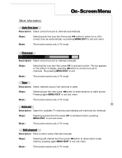
...: Select channels source from antenna or cable. Edit channel Description: Allow to channels manually. On - Mode : This function works only in TV mode. 35 Auto set to add or erase channels manually. The bar appears on or off to correct tune set to exit sub menu. Mode : This function works only in TV mode. Re-pressing MENU/EXIT to exit sub menu. Pressing again MENU/EXIT to...
...: Select channels source from antenna or cable. Edit channel Description: Allow to channels manually. On - Mode : This function works only in TV mode. 35 Auto set to add or erase channels manually. The bar appears on or off to correct tune set to exit sub menu. Mode : This function works only in TV mode. Re-pressing MENU/EXIT to exit sub menu. Pressing again MENU/EXIT to...

User Manual
Page 36
..., channel number, or the resolution of Zoom, UP, Left, Right, Down, Power, Mute and Vol +/will show up when the active window is the source selection: TV, AV1, AV2, HDTV, Digital, and Analog. This function does not support some hot key functions on the right upper corner. ACTIVE To select an active window on full screen mode. This function only works on...
..., channel number, or the resolution of Zoom, UP, Left, Right, Down, Power, Mute and Vol +/will show up when the active window is the source selection: TV, AV1, AV2, HDTV, Digital, and Analog. This function does not support some hot key functions on the right upper corner. ACTIVE To select an active window on full screen mode. This function only works on...
User Manual
Page 38
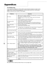
... source by rotation of still pictures include logos, video 38 After- No Color but Sound OK Solutions • Make sure A/C Power is supplied at the wall and/or if a power tap is used, power is available at the tap. • Manually press the Power button located under the front panel controls. • Check the batteries on the remote control • Check whether the Monitor is turned on the High Definition Plasma Display. Problems No Power No Image...
... source by rotation of still pictures include logos, video 38 After- No Color but Sound OK Solutions • Make sure A/C Power is supplied at the wall and/or if a power tap is used, power is available at the tap. • Manually press the Power button located under the front panel controls. • Check the batteries on the remote control • Check whether the Monitor is turned on the High Definition Plasma Display. Problems No Power No Image...
User Manual
Page 39
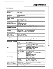
Appendices Specifications Dimmensions Input AC 100 ~ 120V Power Consumption Normal use 535W (maximum) Stand-by condition
Appendices Specifications Dimmensions Input AC 100 ~ 120V Power Consumption Normal use 535W (maximum) Stand-by condition


