

GT- Logic 4 Installation Manual
Page 2
... 4-5 Maximum Door Area 5 Weights and Dimensions 6 ASSEMBLY 7-9 Assemble the Operator (Models T and GT 7 Install the Chain (Models T and GT 8 Assemble the Operator (Model APT 9 TYPICAL INSTALLATION 10-12 Install the Header Bracket 10 Attach the Track to...LiftMaster Monitored Entrapment Protection (LMEP) Devices 22 ADJUSTMENT 23-24 Limit Adjustment 23 Clutch Adjustment (Belt Drive Model Operators 24 TESTING 25 MANUAL RELEASE 26-27 Emergency Disconnect System Model GT and T 26 Emergency Disconnect System Model APT 26 Emergency Disconnect System Model H, GH...
... 4-5 Maximum Door Area 5 Weights and Dimensions 6 ASSEMBLY 7-9 Assemble the Operator (Models T and GT 7 Install the Chain (Models T and GT 8 Assemble the Operator (Model APT 9 TYPICAL INSTALLATION 10-12 Install the Header Bracket 10 Attach the Track to...LiftMaster Monitored Entrapment Protection (LMEP) Devices 22 ADJUSTMENT 23-24 Limit Adjustment 23 Clutch Adjustment (Belt Drive Model Operators 24 TESTING 25 MANUAL RELEASE 26-27 Emergency Disconnect System Model GT and T 26 Emergency Disconnect System Model APT 26 Emergency Disconnect System Model H, GH...

GT- Logic 4 Installation Manual
Page 4
...OPEN & STOP, constant pressure to CLOSE, plus wiring for 3/4 HP and higher (all components were provided. ENTRAPMENT PROTECTION: LiftMaster Monitored Entrapment Protection (LMEP) Photoelectric Sensors (CPS-U Through beam used to open override. See page 29 for emergency manual door.../Operator specifications - TROLLEY TROLLEY OPERATORS CARTON INVENTORY Before beginning your installation check that all GT models) Entrapment Protection Device: Model CPS-U photoelectric sensors (standard) NOTE: The tracks are shipped separately. DESCRIPTION Powerhead assembly Owner's manual and...
...OPEN & STOP, constant pressure to CLOSE, plus wiring for 3/4 HP and higher (all components were provided. ENTRAPMENT PROTECTION: LiftMaster Monitored Entrapment Protection (LMEP) Photoelectric Sensors (CPS-U Through beam used to open override. See page 29 for emergency manual door.../Operator specifications - TROLLEY TROLLEY OPERATORS CARTON INVENTORY Before beginning your installation check that all GT models) Entrapment Protection Device: Model CPS-U photoelectric sensors (standard) NOTE: The tracks are shipped separately. DESCRIPTION Powerhead assembly Owner's manual and...
GT- Logic 4 Installation Manual
Page 5
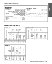
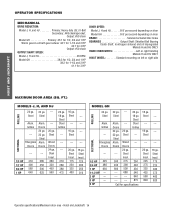
...duty worm gear-in-oil-bath speed reducer Output: #41 chain OUTPUT SHAFT SPEED: Model APT 96 RPM Model GT 113.5 RPM Model T 140 RPM DOOR SPEED (not adjustable): Model APT 6-7" per second Model GT 11-12" per second Model T 11-12" per second BRAKE: Solenoid actuated disc brake on 3/4 and 1 ... --- 16 ga. Steel --- 20 ga. Steel Insul. 260 320 450 560 16 ga. Steel --- 20 ga. Trolley TROLLEY OPERATOR SPECIFICATIONS MECHANICAL DRIVE REDUCTION: Model APT and T Primary: Heavy duty (5L) V-Belt Secondary: #41 chain/sprocket; Steel Insul. 250 325 400 475 --- --- 16 ga. Fiberglass Doors 24 ...
...duty worm gear-in-oil-bath speed reducer Output: #41 chain OUTPUT SHAFT SPEED: Model APT 96 RPM Model GT 113.5 RPM Model T 140 RPM DOOR SPEED (not adjustable): Model APT 6-7" per second Model GT 11-12" per second Model T 11-12" per second BRAKE: Solenoid actuated disc brake on 3/4 and 1 ... --- 16 ga. Steel --- 20 ga. Steel Insul. 260 320 450 560 16 ga. Steel --- 20 ga. Trolley TROLLEY OPERATOR SPECIFICATIONS MECHANICAL DRIVE REDUCTION: Model APT and T Primary: Heavy duty (5L) V-Belt Secondary: #41 chain/sprocket; Steel Insul. 250 325 400 475 --- --- 16 ga. Fiberglass Doors 24 ...
GT- Logic 4 Installation Manual
Page 6
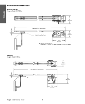
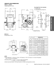
Trolley 6 Optional on APT, T 3/4 and T 1 HP models; For Units with Brake add 3-1/2" (Standard on T 1/3 and 1/2 HP models) MODEL GT Hanging Weight: 140 lbs. 4" (10.16 cm) Door Height Plus 4 feet (minimum) 13.05" (33.15 cm) * 17.5" (44.45 cm) 18.5" (46.99 cm) Weights and dimensions - TROLLEY WEIGHTS AND DIMENSIONS MODELS T AND APT Hanging Weight: 80-110 lbs. 4" (10.16 cm) 14" (35.56 cm) *Door Height Plus 4 feet (minimum) Highest Point of Door Travel 11.63" (29.54 cm) *23.43" (59.51 cm) *-
Trolley 6 Optional on APT, T 3/4 and T 1 HP models; For Units with Brake add 3-1/2" (Standard on T 1/3 and 1/2 HP models) MODEL GT Hanging Weight: 140 lbs. 4" (10.16 cm) Door Height Plus 4 feet (minimum) 13.05" (33.15 cm) * 17.5" (44.45 cm) 18.5" (46.99 cm) Weights and dimensions - TROLLEY WEIGHTS AND DIMENSIONS MODELS T AND APT Hanging Weight: 80-110 lbs. 4" (10.16 cm) 14" (35.56 cm) *Door Height Plus 4 feet (minimum) Highest Point of Door Travel 11.63" (29.54 cm) *23.43" (59.51 cm) *-
GT- Logic 4 Installation Manual
Page 7
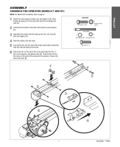
Trolley TROLLEY ASSEMBLY ASSEMBLE THE OPERATOR (MODELS T AND GT) NOTE: For Model APT assembly refer to the track with bolts (F) and washers (D). 3 Assemble the trolley with nuts (B). 1 HARDWARE A Bolt 3/8"-16 x 3/4" B Flange Hex Nut 3/8"-16 C Take Up Bolt D E ...
Trolley TROLLEY ASSEMBLY ASSEMBLE THE OPERATOR (MODELS T AND GT) NOTE: For Model APT assembly refer to the track with bolts (F) and washers (D). 3 Assemble the trolley with nuts (B). 1 HARDWARE A Bolt 3/8"-16 x 3/4" B Flange Hex Nut 3/8"-16 C Take Up Bolt D E ...
GT- Logic 4 Installation Manual
Page 8
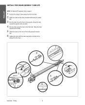
... idler. Wrap the chain around the operator drive sprocket. 4 Run the chain along the track to the operator. Trolley 8 TROLLEY INSTALL THE CHAIN (MODELS T AND GT) NOTE: For Model APT assembly refer to page 9. 1 Position the trolley 2 inches away from the front idler. 2 Attach the chain to the trolley threaded shaft using...
... idler. Wrap the chain around the operator drive sprocket. 4 Run the chain along the track to the operator. Trolley 8 TROLLEY INSTALL THE CHAIN (MODELS T AND GT) NOTE: For Model APT assembly refer to page 9. 1 Position the trolley 2 inches away from the front idler. 2 Attach the chain to the trolley threaded shaft using...
GT- Logic 4 Installation Manual
Page 9
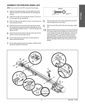
... back and forth past the drive chain to ensure there is not an APT, proceed to the next page. TROLLEY ASSEMBLE THE OPERATOR (MODEL APT) NOTE: If your model is no binding. 7 Run the chain along the track to the front idler. A Bolt 3/8"-16 x 3/4" B Flange Hex Nut 3/8"-16 3 8 Slide the trolley onto...
... back and forth past the drive chain to ensure there is not an APT, proceed to the next page. TROLLEY ASSEMBLE THE OPERATOR (MODEL APT) NOTE: If your model is no binding. 7 Run the chain along the track to the front idler. A Bolt 3/8"-16 x 3/4" B Flange Hex Nut 3/8"-16 3 8 Slide the trolley onto...

GT- Logic 4 Installation Manual
Page 13
... STOP, constant pressure to CLOSE, plus wiring for manual door operation Model HJ Includes both floor level disconnect systems stated above ENTRAPMENT PROTECTION: LiftMaster Monitored Entrapment Protection (LMEP) Photoelectric Sensors (CPS-U Through beam used ... 60Hz 8.5 11.2 13.6 16 230-1Ø, 60Hz 4.2 5.6 6.8 8 208/230-3Ø, 60Hz 3 3.1 4 6 460-3Ø, 60Hz 1.5 1.75 2 3 575-3Ø, 60Hz 1.3 1.4 1.6 1.8 Model GH Voltage-Phase 1/2 HP 3/4 HP 1 HP 1-1/2 HP 2 HP 3 HP 115-1Ø, 60Hz 11.2 13.6 16 20 - - 230-1Ø, 60Hz 5.6 6.8 8 10 - - 208/230-3Ø, ...
... STOP, constant pressure to CLOSE, plus wiring for manual door operation Model HJ Includes both floor level disconnect systems stated above ENTRAPMENT PROTECTION: LiftMaster Monitored Entrapment Protection (LMEP) Photoelectric Sensors (CPS-U Through beam used ... 60Hz 8.5 11.2 13.6 16 230-1Ø, 60Hz 4.2 5.6 6.8 8 208/230-3Ø, 60Hz 3 3.1 4 6 460-3Ø, 60Hz 1.5 1.75 2 3 575-3Ø, 60Hz 1.3 1.4 1.6 1.8 Model GH Voltage-Phase 1/2 HP 3/4 HP 1 HP 1-1/2 HP 2 HP 3 HP 115-1Ø, 60Hz 11.2 13.6 16 20 - - 230-1Ø, 60Hz 5.6 6.8 8 10 - - 208/230-3Ø, ...
GT- Logic 4 Installation Manual
Page 14
... 400 350 3/4 HP 560 500 1 HP 640 625 --- --- 20 ga. Steel Steel Grilles --- --- --- 210 280 380 475 16 ga. Steel Insul. 125 200 250 310 MODEL GH 24 ga. SECTIONAL Fiberglass Doors --- 1/2 HP 325 3/4 HP 480 1 HP 650 1-1/2 HP --- 2 HP --- 3 HP --- 5 HP 22 ga. Doors 24 ga. 22... 560 ------- --- --- 20 ga. Fiberglass Doors Alum. Steel Alum. Steel Alum. Steel Insul. 275 390 500 680 ----- 20 ga. 18 ga. Output: #50 chain Model GH Primary: 45:1 for 1/2, 3/4 and 1 HP Worm gear-in-oil bath gear reducer 44:1 for 1-1/2 and 2 HP 42:1 for 3 HP Output: #50 chain OUTPUT...
... 400 350 3/4 HP 560 500 1 HP 640 625 --- --- 20 ga. Steel Steel Grilles --- --- --- 210 280 380 475 16 ga. Steel Insul. 125 200 250 310 MODEL GH 24 ga. SECTIONAL Fiberglass Doors --- 1/2 HP 325 3/4 HP 480 1 HP 650 1-1/2 HP --- 2 HP --- 3 HP --- 5 HP 22 ga. Doors 24 ga. 22... 560 ------- --- --- 20 ga. Fiberglass Doors Alum. Steel Alum. Steel Alum. Steel Insul. 275 390 500 680 ----- 20 ga. 18 ga. Output: #50 chain Model GH Primary: 45:1 for 1/2, 3/4 and 1 HP Worm gear-in-oil bath gear reducer 44:1 for 1-1/2 and 2 HP 42:1 for 3 HP Output: #50 chain OUTPUT...
GT- Logic 4 Installation Manual
Page 15
...-63/64 3-1/2 27 13-63/64 3-1/2 28-5/8 15-15/64 3-15/16 NOTES: 1) Output shaft with Models H and HJ ONLY 4.56" (11.58 cm) HOIST AND JACKSHAFT MODEL GH Hanging Weight: 140 lbs. X = 3-5/8"; Wall Mounting B - WEIGHTS AND DIMENSIONS MODELS J, H AND HJ Hanging Weight: 80-110 lbs. 14.5" (36.83 cm) 6.94" (17.63 cm...
...-63/64 3-1/2 27 13-63/64 3-1/2 28-5/8 15-15/64 3-15/16 NOTES: 1) Output shaft with Models H and HJ ONLY 4.56" (11.58 cm) HOIST AND JACKSHAFT MODEL GH Hanging Weight: 140 lbs. X = 3-5/8"; Wall Mounting B - WEIGHTS AND DIMENSIONS MODELS J, H AND HJ Hanging Weight: 80-110 lbs. 14.5" (36.83 cm) 6.94" (17.63 cm...

GT- Logic 4 Installation Manual
Page 16
... hand chain systems, the handing of the operator must : a. Permit the operator to be determined at the time of balance. AVERTISSEMENT For models H and HJ with the drive shaft parallel to remain functional, install an interlock switch. • ALWAYS call a trained door systems technician ...the door shaft. An unbalanced door may be used if installing ANY brackets. Be rigid to structural supports of the model number (R or L). b. On models J, H, HJ and GH operators the drive sprocket can cause SERIOUS PERSONAL INJURY. • Disable ALL locks and remove ALL ropes connected to...
... hand chain systems, the handing of the operator must : a. Permit the operator to be determined at the time of balance. AVERTISSEMENT For models H and HJ with the drive shaft parallel to remain functional, install an interlock switch. • ALWAYS call a trained door systems technician ...the door shaft. An unbalanced door may be used if installing ANY brackets. Be rigid to structural supports of the model number (R or L). b. On models J, H, HJ and GH operators the drive sprocket can cause SERIOUS PERSONAL INJURY. • Disable ALL locks and remove ALL ropes connected to...
GT- Logic 4 Installation Manual
Page 20
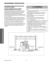
... steady when the sensor is properly connected and aligned. The photoelectric sensors must be disabled. Use with LiftMaster Commercial Door Operators ONLY. InInvviissiibblleeLLigighht tBeBaemam PrPotreoctteiocntiAorneaArea PhSoafteoteylRecevtreircsiSngensor 6"S(e1n5socrm) max. WARNING To prevent possible SERIOUS INJURY ...wiring AVERTISSEMENT the installation of Garage- above the floor. The operator comes standard with the photoelectric sensors model CPS-U, additional entrapment devices are for purchase (see accessories). If AVERTISSEMENT an obstruction breaks the light beam...
... steady when the sensor is properly connected and aligned. The photoelectric sensors must be disabled. Use with LiftMaster Commercial Door Operators ONLY. InInvviissiibblleeLLigighht tBeBaemam PrPotreoctteiocntiAorneaArea PhSoafteoteylRecevtreircsiSngensor 6"S(e1n5socrm) max. WARNING To prevent possible SERIOUS INJURY ...wiring AVERTISSEMENT the installation of Garage- above the floor. The operator comes standard with the photoelectric sensors model CPS-U, additional entrapment devices are for purchase (see accessories). If AVERTISSEMENT an obstruction breaks the light beam...
GT- Logic 4 Installation Manual
Page 22
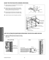
above floor WIRE THE LIFTMASTER MONITORED ENTRAPMENT PROTECTION (LMEP) DEVICES 1 Connect the LiftMaster Monitored Entrapment Protection (LMEP) device to the logic board according to the operator (see below : CPS-U and CPS-UN4 CPS-EI POWER 24VAC ...following page) Photoelectric Sensor 6" (15 cm) max. Use insulated staples to secure wire to the wall and ceiling. 4 Connect the sensor wires to the models shown below ). Bell Wire Wing Nut "C" Wrap Wire Indicator Light Sensor Hex Bolt 1/4-20x1-1/2" ENTRAPMENT PROTECTION Secure wire with the provided hardware. Finger tighten ...
above floor WIRE THE LIFTMASTER MONITORED ENTRAPMENT PROTECTION (LMEP) DEVICES 1 Connect the LiftMaster Monitored Entrapment Protection (LMEP) device to the logic board according to the operator (see below : CPS-U and CPS-UN4 CPS-EI POWER 24VAC ...following page) Photoelectric Sensor 6" (15 cm) max. Use insulated staples to secure wire to the wall and ceiling. 4 Connect the sensor wires to the models shown below ). Bell Wire Wing Nut "C" Wrap Wire Indicator Light Sensor Hex Bolt 1/4-20x1-1/2" ENTRAPMENT PROTECTION Secure wire with the provided hardware. Finger tighten ...
GT- Logic 4 Installation Manual
Page 24
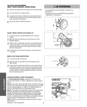
...protection. By removing the centrifugal switch on single phase motors, the leading cause of motor failures is eliminated. (Auxiliary Reversal System not applicable on models GH and GT.) NOTE: This feature is NOT a substitute for a safety sensing device. Clutch adjustment 24 LOSE OPEN RPM Sensor Logic Board We ...Re-tighten the clutch nut until there is just enough tension to permit smooth operation of the shaft. AVERTISSEMENT Torque Nut Set Screws MODEL GH (OPTIONAL MODIFICATION) 1 Loosen set screw that is obstructed. 4 Secure the clutch nut with the cotter pin. Adjustment -
...protection. By removing the centrifugal switch on single phase motors, the leading cause of motor failures is eliminated. (Auxiliary Reversal System not applicable on models GH and GT.) NOTE: This feature is NOT a substitute for a safety sensing device. Clutch adjustment 24 LOSE OPEN RPM Sensor Logic Board We ...Re-tighten the clutch nut until there is just enough tension to permit smooth operation of the shaft. AVERTISSEMENT Torque Nut Set Screws MODEL GH (OPTIONAL MODIFICATION) 1 Loosen set screw that is obstructed. 4 Secure the clutch nut with the cotter pin. Adjustment -
GT- Logic 4 Installation Manual
Page 26
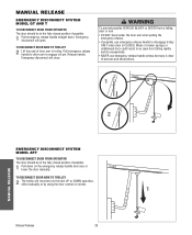
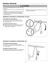
...the door arm when pulling the emergency release. • If possible, use emergency release handle unless doorway is CLOSED. MANUAL RELEASE EMERGENCY DISCONNECT SYSTEM MODEL GT AND T TO DISCONNECT DOOR FROM OPERATOR The door should be in the fully closed position if possible. 1 Pull down . Pull emergency .... TO RECONNECT DOOR ARM TO TROLLEY 2 Lift free end of persons and obstructions. 1 AVERTISSEMENT ATTENTION 2 NOTICE MANUAL RELEASE EMERGENCY DISCONNECT SYSTEM MODEL APT TO DISCONNECT DOOR FROM OPERATOR The door should be in an open . Emergency disconnect will close.
...the door arm when pulling the emergency release. • If possible, use emergency release handle unless doorway is CLOSED. MANUAL RELEASE EMERGENCY DISCONNECT SYSTEM MODEL GT AND T TO DISCONNECT DOOR FROM OPERATOR The door should be in the fully closed position if possible. 1 Pull down . Pull emergency .... TO RECONNECT DOOR ARM TO TROLLEY 2 Lift free end of persons and obstructions. 1 AVERTISSEMENT ATTENTION 2 NOTICE MANUAL RELEASE EMERGENCY DISCONNECT SYSTEM MODEL APT TO DISCONNECT DOOR FROM OPERATOR The door should be in an open . Emergency disconnect will close.
GT- Logic 4 Installation Manual
Page 27
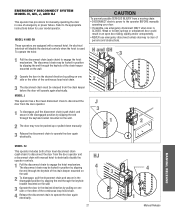
...disconnect chain to engage the hoist mechanism. An electrical interlock will operate again electrically. HJ 4 27 3 4 2 1 Manual Release MODEL H AND GH These operators are equipped with manual hoist to electrically disable the operator controls. 1 Pull the disconnect chain to operate the door again ...open door falling rapidly and/or unexpectedly. • NEVER use emergency disconnect ONLY when door is used. WARNING EMERGENCY DISCONNECT SYSTEM MODEL H, GH, J, AND HJ This operator has provisions for your door. • If possible, use emergency disconnect unless doorway is clear ...
...disconnect chain to engage the hoist mechanism. An electrical interlock will operate again electrically. HJ 4 27 3 4 2 1 Manual Release MODEL H AND GH These operators are equipped with manual hoist to electrically disable the operator controls. 1 Pull the disconnect chain to operate the door again ...open door falling rapidly and/or unexpectedly. • NEVER use emergency disconnect ONLY when door is used. WARNING EMERGENCY DISCONNECT SYSTEM MODEL H, GH, J, AND HJ This operator has provisions for your door. • If possible, use emergency disconnect unless doorway is clear ...

GT- Logic 4 Installation Manual
Page 36
...close lights will be performed by a trained door systems technician. MAINTENANCE 36 Maintenance BeAlt TTENTION Check condition and tension. Bearings and Shafts LiftMaster Monitored Entrapment Protection (LMEP) Check for continuous operation. • Do not lubricate clutch or V-belt. Repeat ALL procedures.... Check at the factory and should not need additional adjustment for some models. z Inspect and service whenever a malfunction is adjusted at the intervals listed in service. Start with an odometer to show how...
...close lights will be performed by a trained door systems technician. MAINTENANCE 36 Maintenance BeAlt TTENTION Check condition and tension. Bearings and Shafts LiftMaster Monitored Entrapment Protection (LMEP) Check for continuous operation. • Do not lubricate clutch or V-belt. Repeat ALL procedures.... Check at the factory and should not need additional adjustment for some models. z Inspect and service whenever a malfunction is adjusted at the intervals listed in service. Start with an odometer to show how...
GT- Logic 4 Installation Manual
Page 41
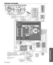
... (VER. 4.0) 1 PHASE WIRING DIAGRAM 115V MOTOR CONNECTION 230V MOTOR CONNECTION NOTE: Gray (GY) and purple (PU) motor wires are reversed for LiftMaster Monitored Entrapment Protection (LMEP) device connections Hoist Interlock When Present TMR DEF (BL) SWITCH (YE) Sensing Edge Maintenance Alert LED (RD) (WH)... 1 2 3 4 RPM Board R1 R2 R3 Radio WIRING DIAGRAMS Refer to NO on Bypass L/S and to page 26 for H and HJ right hand models and all GH and J models. White wires connect the COM on BYPASS L/S and LOCK SENSOR switch to NC on Open L/S. (WH) (RD) (PU) (WH) COM OPEN L/S ...
... (VER. 4.0) 1 PHASE WIRING DIAGRAM 115V MOTOR CONNECTION 230V MOTOR CONNECTION NOTE: Gray (GY) and purple (PU) motor wires are reversed for LiftMaster Monitored Entrapment Protection (LMEP) device connections Hoist Interlock When Present TMR DEF (BL) SWITCH (YE) Sensing Edge Maintenance Alert LED (RD) (WH)... 1 2 3 4 RPM Board R1 R2 R3 Radio WIRING DIAGRAMS Refer to NO on Bypass L/S and to page 26 for H and HJ right hand models and all GH and J models. White wires connect the COM on BYPASS L/S and LOCK SENSOR switch to NC on Open L/S. (WH) (RD) (PU) (WH) COM OPEN L/S ...
GT- Logic 4 Installation Manual
Page 42
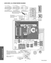
... WIRING DIAGRAMS White wires connect the COM on BYPASS L/S and Lock Sensor switch to page 26 for H and HJ right hand models and all GH and J models. Sensing Edge Refer to NC on LOCK SENSOR switch. LOGIC (VER. 4.0) 3 PHASE WIRING DIAGRAM 230V BRAKE (WHEN PRESENT) ...(BL/BK) 208/230V MOTOR CONNECTION 460V MOTOR CONNECTION 575V MOTOR CONNECTION NOTE: Gray (GY) and purple (PU) motor wires are reversed for LiftMaster Monitored Entrapment Protection (LMEP) device connections Hoist Interlock When Present TMR DEF (BL) SWITCH (YE) Maintenance Alert LED (RD) (WH) Open Close...
... WIRING DIAGRAMS White wires connect the COM on BYPASS L/S and Lock Sensor switch to page 26 for H and HJ right hand models and all GH and J models. Sensing Edge Refer to NC on LOCK SENSOR switch. LOGIC (VER. 4.0) 3 PHASE WIRING DIAGRAM 230V BRAKE (WHEN PRESENT) ...(BL/BK) 208/230V MOTOR CONNECTION 460V MOTOR CONNECTION 575V MOTOR CONNECTION NOTE: Gray (GY) and purple (PU) motor wires are reversed for LiftMaster Monitored Entrapment Protection (LMEP) device connections Hoist Interlock When Present TMR DEF (BL) SWITCH (YE) Maintenance Alert LED (RD) (WH) Open Close...
GT- Logic 4 User Manual
Page 6
... Release handle. PRECAUCIÓN TO RECONNECT DOOR ARM TO TROLLEY 2 The trolley will close. AVE AV 2 NOTICE EMERGENCY DISCONNECT SYSTEM MODEL APT TO DISCONNECT DOOR FROM OPERATOR ADVERTENCIA The door should be in the fully closed position if possible. 1 Pull down . Emergency ...disconnect will reconnect on the emergency release handle and raise or lower the door manually. EMERGENCY DISCONNECT SYSTEM MODEL GT AND T TO DISCONNECT DOOR FROM OPERATOR The door should be in the fully closed position if possible. MANUAL RELEASE WARNING W ...
... Release handle. PRECAUCIÓN TO RECONNECT DOOR ARM TO TROLLEY 2 The trolley will close. AVE AV 2 NOTICE EMERGENCY DISCONNECT SYSTEM MODEL APT TO DISCONNECT DOOR FROM OPERATOR ADVERTENCIA The door should be in the fully closed position if possible. 1 Pull down . Emergency ...disconnect will reconnect on the emergency release handle and raise or lower the door manually. EMERGENCY DISCONNECT SYSTEM MODEL GT AND T TO DISCONNECT DOOR FROM OPERATOR The door should be in the fully closed position if possible. MANUAL RELEASE WARNING W ...


