
GT- Logic 4 Installation Manual
Page 5
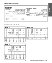
...350 3/4 HP 560 500 1 HP 640 625 20 ga. Steel Insul. 175 250 325 400 --- --- 16 ga. Steel Wood Doors 24 ga. TROLLEY OPERATOR SPECIFICATIONS MECHANICAL DRIVE REDUCTION: Model APT and T Primary: Heavy duty (5L) V-Belt Secondary: #41 chain/sprocket; Steel --- 20 ga. Steel Insul. 320 450 500 550 16...-in-oil-bath speed reducer Output: #41 chain OUTPUT SHAFT SPEED: Model APT 96 RPM Model GT 113.5 RPM Model T 140 RPM DOOR SPEED (not adjustable): Model APT 6-7" per second Model GT 11-12" per second Model T 11-12" per second BRAKE: Solenoid actuated disc brake on 3/4 and 1 HP, ...
...350 3/4 HP 560 500 1 HP 640 625 20 ga. Steel Insul. 175 250 325 400 --- --- 16 ga. Steel Wood Doors 24 ga. TROLLEY OPERATOR SPECIFICATIONS MECHANICAL DRIVE REDUCTION: Model APT and T Primary: Heavy duty (5L) V-Belt Secondary: #41 chain/sprocket; Steel --- 20 ga. Steel Insul. 320 450 500 550 16...-in-oil-bath speed reducer Output: #41 chain OUTPUT SHAFT SPEED: Model APT 96 RPM Model GT 113.5 RPM Model T 140 RPM DOOR SPEED (not adjustable): Model APT 6-7" per second Model GT 11-12" per second Model T 11-12" per second BRAKE: Solenoid actuated disc brake on 3/4 and 1 HP, ...
GH LOGIC VERSION 2 Manual
Page 2
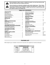
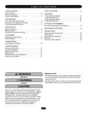
...safety related issues. TABLE OF CONTENTS SPECIFICATIONS Packing List 2 Motor Specification 3 Electrical Specifications 3 Mechanical Specifications 3 Safety Specifications 3 Weights & Dimensions 3 PREPARATION Site 4 Operator 4 INSTALLATION INSTRUCTIONS ...Emergency Manual Operation 6 Contact Reversing Edge Device 6 Sensing Edges & Photo Eyes 7 LIMIT SWITCH ADJUSTMENT Limit Location 7 Adjustment 7 POWER & CONTROL WIRING Safety Warnings 8 Power Wiring 9 Ground Wiring 9 Control Station ...02-103L DESCRIPTION GH PARTS BOX 29 FT HAND CHAIN GH PARTS BAG # 50 CHAIN, 106 PITCH 3 BUTTON CONTROL STATION...
...safety related issues. TABLE OF CONTENTS SPECIFICATIONS Packing List 2 Motor Specification 3 Electrical Specifications 3 Mechanical Specifications 3 Safety Specifications 3 Weights & Dimensions 3 PREPARATION Site 4 Operator 4 INSTALLATION INSTRUCTIONS ...Emergency Manual Operation 6 Contact Reversing Edge Device 6 Sensing Edges & Photo Eyes 7 LIMIT SWITCH ADJUSTMENT Limit Location 7 Adjustment 7 POWER & CONTROL WIRING Safety Warnings 8 Power Wiring 9 Ground Wiring 9 Control Station ...02-103L DESCRIPTION GH PARTS BOX 29 FT HAND CHAIN GH PARTS BAG # 50 CHAIN, 106 PITCH 3 BUTTON CONTROL STATION...
GH LOGIC VERSION 2 Manual
Page 3
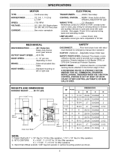
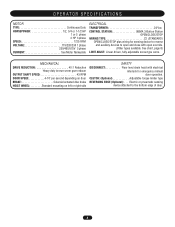
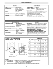
...PHOTO EYES: (Optional) Thru beam or retro reflective devices used to provide non-contact safety protection. LIMIT ADJUST Linear driven, fully adjustable screw type cams. Adjustable to the bottom edge of door. depending on door BRAKE Solenoid actuated disc brake HOIST WHEEL Standard mounting... on left or right side SAFETY DISCONNECT Floor level chain hoist with electrical interlock for optional wiring types and operating modes. MECHANICAL...
...PHOTO EYES: (Optional) Thru beam or retro reflective devices used to provide non-contact safety protection. LIMIT ADJUST Linear driven, fully adjustable screw type cams. Adjustable to the bottom edge of door. depending on door BRAKE Solenoid actuated disc brake HOIST WHEEL Standard mounting... on left or right side SAFETY DISCONNECT Floor level chain hoist with electrical interlock for optional wiring types and operating modes. MECHANICAL...
GH LOGIC 3 Manual
Page 2
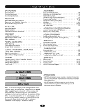
...PROGRAMMING Red/Green Warning Light Card 24 Resetting Factory Defaults - The hazard may come from something mechanical or from electric shock. AVERTISSEMENT AAAVVETETRRETTNIISSTSSIOEEMNMEENNTT 2 AAVVEERRTTISISSSEEMMEENNTT Read the warnings carefully. TABLE OF CONTENTS SPECIFICATIONS... Mounting Conversion 5 INSTALLATION Mount the Operator 6 Manual Operation 7 Entrapment Protection Accessories 8 ADJUSTMENT Limit Switch Adjustment 8 Adjust Torque Limiter Clutch 9 Brake Adjustment 9 POWER & GROUND WIRING Safety Warnings 10 Power Wiring Connections 10 Ground Wiring Connections...
...PROGRAMMING Red/Green Warning Light Card 24 Resetting Factory Defaults - The hazard may come from something mechanical or from electric shock. AVERTISSEMENT AAAVVETETRRETTNIISSTSSIOEEMNMEENNTT 2 AAVVEERRTTISISSSEEMMEENNTT Read the warnings carefully. TABLE OF CONTENTS SPECIFICATIONS... Mounting Conversion 5 INSTALLATION Mount the Operator 6 Manual Operation 7 Entrapment Protection Accessories 8 ADJUSTMENT Limit Switch Adjustment 8 Adjust Torque Limiter Clutch 9 Brake Adjustment 9 POWER & GROUND WIRING Safety Warnings 10 Power Wiring Connections 10 Ground Wiring Connections...
GH LOGIC 3 Manual
Page 4
LIMIT ADJUST Linear driven, fully adjustable screw type cams MECHANICAL DRIVE REDUCTION 45:1 for 1/2, 3/4, and 1 HP 44:1 for 1-1/2, 2 42:1 for 3 HP OUTPUT SHAFT SPEED 38.3 for 1/2, 3/4, and 1 HP 39.2 for 1-1/2 and 2 HP 41.1 for 3 HP ... mounting on left or right side SAFETY DISCONNECT Floor level chain hoist with open and close with electrical interlock for manual door operation CLUTCH (Optional Adjustable torque limiter type SAFETY PHOTO EYES (Optional CPS-L): Through beam or retro reflective devices used to provide non-contact safety protection SAFETY EDGE (Optional): Electric...
LIMIT ADJUST Linear driven, fully adjustable screw type cams MECHANICAL DRIVE REDUCTION 45:1 for 1/2, 3/4, and 1 HP 44:1 for 1-1/2, 2 42:1 for 3 HP OUTPUT SHAFT SPEED 38.3 for 1/2, 3/4, and 1 HP 39.2 for 1-1/2 and 2 HP 41.1 for 3 HP ... mounting on left or right side SAFETY DISCONNECT Floor level chain hoist with open and close with electrical interlock for manual door operation CLUTCH (Optional Adjustable torque limiter type SAFETY PHOTO EYES (Optional CPS-L): Through beam or retro reflective devices used to provide non-contact safety protection SAFETY EDGE (Optional): Electric...
GH -Mechanical New style w/ thermal overload change Manual
Page 2
... operator unless you do not comply with the warnings that accompany it. Model GH 22 Model GH 23 Control Connection Diagram 24 WARNING Mechanical CAWWUAATRRIONNNIINNGG Electrical CAWUATRIONNING When you see these Safety Symbols and Signal Words on the.../Left Conversion 5 Horizontal Mounting Conversion 5 INSTALLATION Mount the Operator 6 Manual Operation 7 Entrapment Protection Accessories 8 ADJUSTMENT Adjust Torque Limiter Clutch 9 Brake Adjustment 9 POWER WIRING Power Wiring Connections 10 CONTROL WIRING Determine Wiring Type 11 Special Control Wiring 11 Mounting Instructions...
... operator unless you do not comply with the warnings that accompany it. Model GH 22 Model GH 23 Control Connection Diagram 24 WARNING Mechanical CAWWUAATRRIONNNIINNGG Electrical CAWUATRIONNING When you see these Safety Symbols and Signal Words on the.../Left Conversion 5 Horizontal Mounting Conversion 5 INSTALLATION Mount the Operator 6 Manual Operation 7 Entrapment Protection Accessories 8 ADJUSTMENT Adjust Torque Limiter Clutch 9 Brake Adjustment 9 POWER WIRING Power Wiring Connections 10 CONTROL WIRING Determine Wiring Type 11 Special Control Wiring 11 Mounting Instructions...
GH -Mechanical New style w/ thermal overload change Manual
Page 4
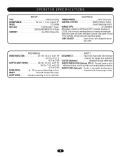
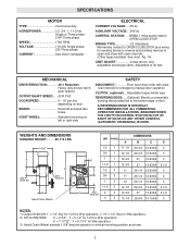
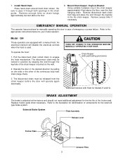
Electric or pneumatic sensing device attached to open and close with electrical interlock for emergency manual door operation. CLUTCH: (Optional Adjustable torque limiter type REVERSING EDGE (Optional): . . . OPERATOR SPECIFICATIONS MOTOR TYPE Continuous Duty HORSEPOWER 1/2, 3/4 or 1-1/2 HP 1 or 3 phase 2 ...reverse and auxiliary devices to the bottom edge of door. 4 See chart, page 8) LIMIT ADJST: Linear driven, fully adjustable screw type cams. MECHANICAL DRIVE REDUCTION 40:1 Reduction Heavy duty bronze worm gear reducer OUTPUT SHAFT SPEED 43 RPM DOOR SPEED 4-10" per second ...
Electric or pneumatic sensing device attached to open and close with electrical interlock for emergency manual door operation. CLUTCH: (Optional Adjustable torque limiter type REVERSING EDGE (Optional): . . . OPERATOR SPECIFICATIONS MOTOR TYPE Continuous Duty HORSEPOWER 1/2, 3/4 or 1-1/2 HP 1 or 3 phase 2 ...reverse and auxiliary devices to the bottom edge of door. 4 See chart, page 8) LIMIT ADJST: Linear driven, fully adjustable screw type cams. MECHANICAL DRIVE REDUCTION 40:1 Reduction Heavy duty bronze worm gear reducer OUTPUT SHAFT SPEED 43 RPM DOOR SPEED 4-10" per second ...
GH Logic 4 Quick Start Guide Manual
Page 1
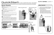
...To operate the hoist, pull the disconnect chain (small chain) to engage the hoist mechanism. Operator Mounting 1a Wall Mount: The operator should generally be locked in case of...drive before securing to the operator BEFORE manually operating your door. QuickStart for the model GH door operator IMPORTANT: This QuickStart is taut (not tight). These instructions are positioned ...be installed below the door shaft. Mount Chain Keeper 4' above floor Chain Keeper (with adjustments. 11 Radio programming and troubleshooting instructions inside cover of operator. 1a Right Hand Wall Mounted ...
...To operate the hoist, pull the disconnect chain (small chain) to engage the hoist mechanism. Operator Mounting 1a Wall Mount: The operator should generally be locked in case of...drive before securing to the operator BEFORE manually operating your door. QuickStart for the model GH door operator IMPORTANT: This QuickStart is taut (not tight). These instructions are positioned ...be installed below the door shaft. Mount Chain Keeper 4' above floor Chain Keeper (with adjustments. 11 Radio programming and troubleshooting instructions inside cover of operator. 1a Right Hand Wall Mounted ...
GH LOGIC VERSION 1 Manual
Page 2
... Wheel extends 1-5/8" beyond operator in vertical mounting position as shown. 2 DOOR SPEED 4 - 10" per sec. See chart, Pg. 14) LIMIT ADJUST Linear driven, fully adjustable screw type cams. Adjustable to the bottom edge of door. Y = 9-1/16" for 1/2 thru 2Hp operators X = 7-17/32"; SPECIFICATIONS MOTOR TYPE Continuous duty HORSEPOWER 1/2,... nameplate ELECTRICAL CURRENT VOLTAGE:.....5V dc AUXILIARY VOLTAGE: ...24V dc CONTROL STATION: .....NEMA 1 three button station. MECHANICAL DRIVE REDUCTION 40:1 Reduction Heavy duty bronze worm gear reducer OUTPUT SHAFT SPEED: .....43 R.P.M.
... Wheel extends 1-5/8" beyond operator in vertical mounting position as shown. 2 DOOR SPEED 4 - 10" per sec. See chart, Pg. 14) LIMIT ADJUST Linear driven, fully adjustable screw type cams. Adjustable to the bottom edge of door. Y = 9-1/16" for 1/2 thru 2Hp operators X = 7-17/32"; SPECIFICATIONS MOTOR TYPE Continuous duty HORSEPOWER 1/2,... nameplate ELECTRICAL CURRENT VOLTAGE:.....5V dc AUXILIARY VOLTAGE: ...24V dc CONTROL STATION: .....NEMA 1 three button station. MECHANICAL DRIVE REDUCTION 40:1 Reduction Heavy duty bronze worm gear reducer OUTPUT SHAFT SPEED: .....43 R.P.M.
GH LOGIC VERSION 1 Manual
Page 5
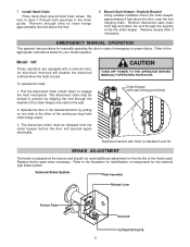
... chain around hand chain wheel. Remove excess links if necessary. Refer to engage the hoist mechanism. CAUTION TURN OFF POWER TO THE OPERATOR BEFORE MANUALLY OPERATING YOUR DOOR. Model GH These operators are equipped with Hoist for Models H and HJ BRAKE ADJUSTMENT The brake is used. An electrical interlock will operate again electrically.
... chain around hand chain wheel. Remove excess links if necessary. Refer to engage the hoist mechanism. CAUTION TURN OFF POWER TO THE OPERATOR BEFORE MANUALLY OPERATING YOUR DOOR. Model GH These operators are equipped with Hoist for Models H and HJ BRAKE ADJUSTMENT The brake is used. An electrical interlock will operate again electrically.
GH-MECHANICAL Manual
Page 2
...RECOMMENDED FOR ALL COMMERCIAL OPERATOR INSTALLATIONS. DOOR SPEED 4 - 10" per sec. Y = 5-1/2" for emergency manual door operation CLUTCH: (optional)....Adjustable torque limiter type REVERSING EDGE:.....(Optional) Electric or pneumatic sensing device attached to OPEN/CLOSE/STOP plus wiring for 3Hp operators. 2) MT'G ...WHEN THE 3 BUTTON CONTROL STATION IS OUT OF SIGHT OF DOOR OR ANY OTHER CONTROL (AUTOMATIC OR MANUAL) IS USED. MECHANICAL DRIVE REDUCTION 40:1 Reduction Heavy duty bronze worm gear reducer OUTPUT SHAFT SPEED: .....43 R.P.M. WEIGHTS AND DIMENSIONS HANGING WEIGHT: ...
...RECOMMENDED FOR ALL COMMERCIAL OPERATOR INSTALLATIONS. DOOR SPEED 4 - 10" per sec. Y = 5-1/2" for emergency manual door operation CLUTCH: (optional)....Adjustable torque limiter type REVERSING EDGE:.....(Optional) Electric or pneumatic sensing device attached to OPEN/CLOSE/STOP plus wiring for 3Hp operators. 2) MT'G ...WHEN THE 3 BUTTON CONTROL STATION IS OUT OF SIGHT OF DOOR OR ANY OTHER CONTROL (AUTOMATIC OR MANUAL) IS USED. MECHANICAL DRIVE REDUCTION 40:1 Reduction Heavy duty bronze worm gear reducer OUTPUT SHAFT SPEED: .....43 R.P.M. WEIGHTS AND DIMENSIONS HANGING WEIGHT: ...
GH-MECHANICAL Manual
Page 5
Model GH These operators are equipped with Hoist for Models H and HJ BRAKE ADJUSTMENT The brake is used. The disconnect chain may be released from bag and place the end through ...the floor from the chain keeper before the door will disable the electrical controls when the hoist is adjusted at the factory and should not need additional adjustment for manually operating the door in case of emergency or power failure. Remove enough links so chain ...the chain keeper sure to the illustration for identification of the friction pad. Refer to engage the hoist mechanism.
Model GH These operators are equipped with Hoist for Models H and HJ BRAKE ADJUSTMENT The brake is used. The disconnect chain may be released from bag and place the end through ...the floor from the chain keeper before the door will disable the electrical controls when the hoist is adjusted at the factory and should not need additional adjustment for manually operating the door in case of emergency or power failure. Remove enough links so chain ...the chain keeper sure to the illustration for identification of the friction pad. Refer to engage the hoist mechanism.


