
GT- Logic 4 Installation Manual
Page 1
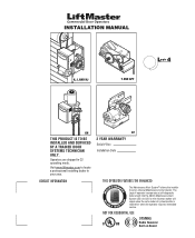
The Logic 4 operator incorporates a self-diagnostic feature built into the (MAS) Maintenance Alert System LED. An LED on Board Visit www.liftmaster.com to set number of cycles/months is reached or when the operator requires immediate service. INSTALLATION MANUAL H, J, AND HJ T AND APT L 4 ogic L3 GH THIS PRODUCT IS TO BE INSTALLED AND SERVICED...
The Logic 4 operator incorporates a self-diagnostic feature built into the (MAS) Maintenance Alert System LED. An LED on Board Visit www.liftmaster.com to set number of cycles/months is reached or when the operator requires immediate service. INSTALLATION MANUAL H, J, AND HJ T AND APT L 4 ogic L3 GH THIS PRODUCT IS TO BE INSTALLED AND SERVICED...

GT- Logic 4 Installation Manual
Page 2
...INSTALLATION 16-17 Determine Mounting Location 16 Mounting 17 Install the Manual Disconnect 17 WIRING 18-19 Power and Ground 18 Control Station 19 ENTRAPMENT PROTECTION 20-22 LiftMaster Monitored Entrapment Protection (LMEP 20 Install the Photoelectric Sensors (Provided ... H, GH, J, and HJ 27 PROGRAMMING 28-35 Introduction to Order Repair Parts 36 TROUBLESHOOTING 37-40 Diagnostic Chart 37 Troubleshooting Guide 38 Troubleshooting Error Codes 39 Troubleshooting Radio Functionality 40 WIRING DIAGRAMS 41-42 Logic (Ver. 4.0) 1 Phase Wiring Diagram 41 Logic (Ver...
...INSTALLATION 16-17 Determine Mounting Location 16 Mounting 17 Install the Manual Disconnect 17 WIRING 18-19 Power and Ground 18 Control Station 19 ENTRAPMENT PROTECTION 20-22 LiftMaster Monitored Entrapment Protection (LMEP 20 Install the Photoelectric Sensors (Provided ... H, GH, J, and HJ 27 PROGRAMMING 28-35 Introduction to Order Repair Parts 36 TROUBLESHOOTING 37-40 Diagnostic Chart 37 Troubleshooting Guide 38 Troubleshooting Error Codes 39 Troubleshooting Radio Functionality 40 WIRING DIAGRAMS 41-42 Logic (Ver. 4.0) 1 Phase Wiring Diagram 41 Logic (Ver...
GT- Logic 4 Installation Manual
Page 23
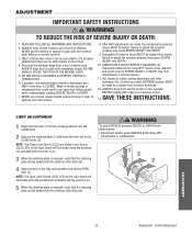
... SEVERE INJURY or DEATH. 7. SAVE THESE INSTRUCTIONS. NOTE: The Close Limit Switch (CLS) and Safety Limit Switch (SLS) LEDs on the logic board will ATTENTION illuminate when the switches are activated and the power is on . 5 When the retaining plate is released, verify that the ...properly may cause SEVERE INJURY and DEATH. 10. WARNING WARNING LIMIT ADJUSTMENT CAUTION 1 Begin with the notches of children. If possible, use manual release handle unless doorway is fully seated with the door in sight until completely closed position to set the OPEN limit (3). WARNING ADJUSTMENT ...
... SEVERE INJURY or DEATH. 7. SAVE THESE INSTRUCTIONS. NOTE: The Close Limit Switch (CLS) and Safety Limit Switch (SLS) LEDs on the logic board will ATTENTION illuminate when the switches are activated and the power is on . 5 When the retaining plate is released, verify that the ...properly may cause SEVERE INJURY and DEATH. 10. WARNING WARNING LIMIT ADJUSTMENT CAUTION 1 Begin with the notches of children. If possible, use manual release handle unless doorway is fully seated with the door in sight until completely closed position to set the OPEN limit (3). WARNING ADJUSTMENT ...
GT- Logic 4 Installation Manual
Page 25
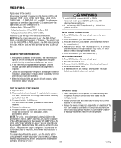
... sensors, turn off . Once the power up process is completed (approximately 2-3 seconds) only the appropriate LED's will continue to manually disconnect the door from obstruction, check photoelectric sensors. If the selector dial is connected to DIAG, push and hold the CLOSE button...learn the photoelectric sensors (LMEP) once they are installed. 4. ADVERTENCIA 2. PRresEs aCndAhoUld tChe ICÓLOSNE button. NOTE: The Logic 4 control board will continue to close direction.) 4. You can close if photoelectric sensors are properly connected. The operator will begin closing...
... sensors, turn off . Once the power up process is completed (approximately 2-3 seconds) only the appropriate LED's will continue to manually disconnect the door from obstruction, check photoelectric sensors. If the selector dial is connected to DIAG, push and hold the CLOSE button...learn the photoelectric sensors (LMEP) once they are installed. 4. ADVERTENCIA 2. PRresEs aCndAhoUld tChe ICÓLOSNE button. NOTE: The Logic 4 control board will continue to close direction.) 4. You can close if photoelectric sensors are properly connected. The operator will begin closing...
GT- Logic 4 Installation Manual
Page 33
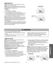
...the logic board. 4. Turn selector dial back to complete programming. All 6. The OPEN LED will not open position. Entrapment Protection (LMEP) device installed (refer to clear the timer, press and release the 1. PROGRAM, press and release the TIMER button, press and TO PROGRAM MANUALLY (...heating and cooling costs. automatically after preset amount of time. 7. Turn the selector dial to complete programming. 6. Once at least one LiftMaster Monitored (TS ,T or FSTS). The OPEN/CLOSE button LEDs will flash to confirm the timer Benefit: The door will vary depending ...
...the logic board. 4. Turn selector dial back to complete programming. All 6. The OPEN LED will not open position. Entrapment Protection (LMEP) device installed (refer to clear the timer, press and release the 1. PROGRAM, press and release the TIMER button, press and TO PROGRAM MANUALLY (...heating and cooling costs. automatically after preset amount of time. 7. Turn the selector dial to complete programming. 6. Once at least one LiftMaster Monitored (TS ,T or FSTS). The OPEN/CLOSE button LEDs will flash to confirm the timer Benefit: The door will vary depending ...
GT- Logic 4 Installation Manual
Page 35
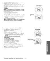
...C2 B2 TS FSTS DIAG OPTN PROG PROGRAMMING Programming - Timer-To-Close = 0 seconds b. The LiftMaster Monitored Entrapment Protection (LMEP) device will still be learned g. Benefit: If the operator does not meet...the door has reached the open position, programming is deactivated f. The remote controls will be manually learned for the door to the desired wiring type. SELECTOR DIAL T E2 D1 C2 B2...MRT button until the MAS led flashes rapidly. The MAS LED will vary depending on logic board. 4. In the event the application requires the MRT be unprogrammed NOTE: Life of...
...C2 B2 TS FSTS DIAG OPTN PROG PROGRAMMING Programming - Timer-To-Close = 0 seconds b. The LiftMaster Monitored Entrapment Protection (LMEP) device will still be learned g. Benefit: If the operator does not meet...the door has reached the open position, programming is deactivated f. The remote controls will be manually learned for the door to the desired wiring type. SELECTOR DIAL T E2 D1 C2 B2...MRT button until the MAS led flashes rapidly. The MAS LED will vary depending on logic board. 4. In the event the application requires the MRT be unprogrammed NOTE: Life of...

GT- Logic 4 Installation Manual
Page 36
... need additional adjustment for some models. Clutch Check and adjust as required. BeAlt TTENTION Check condition and tension. Bearings and Shafts LiftMaster Monitored Entrapment Protection (LMEP) Check for every 3 months. 6. The open and close lights will be performed by a trained ...alignment and functionality. BRAKE (IF PRESENT) A solenoid brake is observed or suspected. Manual Disconnect Check and operate. Motor bearings are available. Press and release the MRT button on the logic board. 4. NOTE: Your operator may look different than the operator shown. MAINTENANCE...
... need additional adjustment for some models. Clutch Check and adjust as required. BeAlt TTENTION Check condition and tension. Bearings and Shafts LiftMaster Monitored Entrapment Protection (LMEP) Check for every 3 months. 6. The open and close lights will be performed by a trained ...alignment and functionality. BRAKE (IF PRESENT) A solenoid brake is observed or suspected. Manual Disconnect Check and operate. Motor bearings are available. Press and release the MRT button on the logic board. 4. NOTE: Your operator may look different than the operator shown. MAINTENANCE...

GT- Logic 4 Installation Manual
Page 38
... Motor thermal overload tripped g) Possible accessory malfunction h) Off Board relay may need to be replaced (see wiring diagram Off Board Relays). ➤ Replace logic board. If Relay A or B lights and the door does not move, off board relay may need to be on. ➤ Set dial to...➤ Unlearn the photoelectric sensors from power source. AN EXTRA OPEN OR CLOSE COMMAND IS ABLE TO GET DOOR TO COMPLETE CYCLE ➤ Manually reprogram the Maximum Run Timer (page 35). THE DOOR WILL OPEN BUT a) The photoelectric sensors, edge or WILL ONLY CLOSE AFTER other sensing ...
... Motor thermal overload tripped g) Possible accessory malfunction h) Off Board relay may need to be replaced (see wiring diagram Off Board Relays). ➤ Replace logic board. If Relay A or B lights and the door does not move, off board relay may need to be on. ➤ Set dial to...➤ Unlearn the photoelectric sensors from power source. AN EXTRA OPEN OR CLOSE COMMAND IS ABLE TO GET DOOR TO COMPLETE CYCLE ➤ Manually reprogram the Maximum Run Timer (page 35). THE DOOR WILL OPEN BUT a) The photoelectric sensors, edge or WILL ONLY CLOSE AFTER other sensing ...

GT- Logic 4 Installation Manual
Page 39
... plugged into the MAS LED. Operator must run as long as an input. TROUBLESHOOTING ERROR CODES Logic 4.0 operators incorporate a self diagnostic feature built into option card receptacles LiftMaster Monitored Entrapment Protection (LMEP) device faulted or removed for list of Motor movement at a time....commands Clutch is cleared or connected. Operator must be unstuck will continue to function normally for any faults (i.e., Bad Limit switch), manually learn Max Run Timer (page 35) OR reset factory defaults (page 35). TROUBLESHOOTING NOTE: Error codes take priority over normal...
... plugged into the MAS LED. Operator must run as long as an input. TROUBLESHOOTING ERROR CODES Logic 4.0 operators incorporate a self diagnostic feature built into option card receptacles LiftMaster Monitored Entrapment Protection (LMEP) device faulted or removed for list of Motor movement at a time....commands Clutch is cleared or connected. Operator must be unstuck will continue to function normally for any faults (i.e., Bad Limit switch), manually learn Max Run Timer (page 35) OR reset factory defaults (page 35). TROUBLESHOOTING NOTE: Error codes take priority over normal...
GT- Logic 4 User Manual
Page 5
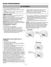
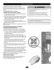
...2. BASIC PROGRAMMING WARNING W To prevent possible SEVERE INJURY or DEATH: CAUTION • Install a LiftMaster Monitored Entrapment Protection (LMEP) • Activate door ONLY when it can be reactivated on the ...after preset time. AVERTISSEMENT PROGRAM, press and release the TIMER button, press and AVE TO PROGRAM MANUALLY (METHOD 1): release the STOP button to clear the timer. 5. AV 4. Press SELECTOR DIAL...and OLS flashes then release. The OPEN LED Operation will vary depending on the logic board. Turn selector dial to 11 and 12 (Common and Timer Defeat). Turn...
...2. BASIC PROGRAMMING WARNING W To prevent possible SEVERE INJURY or DEATH: CAUTION • Install a LiftMaster Monitored Entrapment Protection (LMEP) • Activate door ONLY when it can be reactivated on the ...after preset time. AVERTISSEMENT PROGRAM, press and release the TIMER button, press and AVE TO PROGRAM MANUALLY (METHOD 1): release the STOP button to clear the timer. 5. AV 4. Press SELECTOR DIAL...and OLS flashes then release. The OPEN LED Operation will vary depending on the logic board. Turn selector dial to 11 and 12 (Common and Timer Defeat). Turn...
GT- Logic 4 User Manual
Page 8
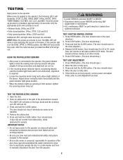
...and hold the CLOSE button. (The door should move in E2 mode. Open the door. NOTE: When the power up process is applied to manually disconnect the door from obstruction, check photoelectric sensors. Press OPEN button. (The door should close.) 4. Allow the door to fully open position in... will glow steadily if wiring connections and alignment are glowing in both the sending and receiving sensors will reverse to the operator on the logic board and the receiving eye LED will light when device(s) are working properly. • Be sure you have read and understand the ...
...and hold the CLOSE button. (The door should move in E2 mode. Open the door. NOTE: When the power up process is applied to manually disconnect the door from obstruction, check photoelectric sensors. Press OPEN button. (The door should close.) 4. Allow the door to fully open position in... will glow steadily if wiring connections and alignment are glowing in both the sending and receiving sensors will reverse to the operator on the logic board and the receiving eye LED will light when device(s) are working properly. • Be sure you have read and understand the ...
GH LOGIC VERSION 2 Manual
Page 1
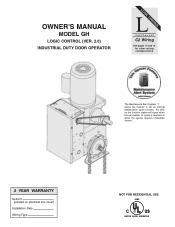
An LED on the 3-button station will signal when the set an internal Maintenance Cycle Counter. OWNER'S MANUAL MODEL GH LOGIC CONTROL (VER. 2.0) INDUSTRIAL DUTY DOOR OPERATOR LOGIC LCONTROL FACTORY SET C2 Wiring See pages 14 and 15 for other wiring configurations PATENT PENDING The Maintenance Alert System TM allows the installer to set number of cycles is reached or when the opener requires immediate service. 2 YEAR WARRANTY Serial # (located on electrical box cover) Installation Date Wiring Type NOT FOR RESIDENTIAL USE 41B6 LISTED DOOR OPERATOR
An LED on the 3-button station will signal when the set an internal Maintenance Cycle Counter. OWNER'S MANUAL MODEL GH LOGIC CONTROL (VER. 2.0) INDUSTRIAL DUTY DOOR OPERATOR LOGIC LCONTROL FACTORY SET C2 Wiring See pages 14 and 15 for other wiring configurations PATENT PENDING The Maintenance Alert System TM allows the installer to set number of cycles is reached or when the opener requires immediate service. 2 YEAR WARRANTY Serial # (located on electrical box cover) Installation Date Wiring Type NOT FOR RESIDENTIAL USE 41B6 LISTED DOOR OPERATOR
GH LOGIC VERSION 2 Manual
Page 11
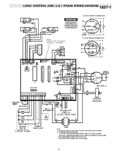
Transformer Primary Voltage same as Line Voltage.. 11 LOGIC CONTROL (VER. 2.0) 1 PHASE WIRING DIAGRAM 1837-1 230 VOLT MOTOR CONNECTION NOTE: Contactor 1 PH / 3 PH jumper should be in 1 PH position. 115 VOLT MOTOR CONNECTION Note: 1) See Ownerʼs Manual for Dip Switch Functions and Programming Procedures 2) TO REVERSE MOTOR DIRECTION 115 VOLTS: ALWAYS EXCHANGE PURPLE & GRAY ALL VOLTS & PHASES. 230 VOLTS: INTERCHANGE PURPLE (E10) & GRAY (E15) WIRES AT LOGIC BOARD. * - BLUE WIRE MUST BE INSULATED ON 230V 1PH. **-
Transformer Primary Voltage same as Line Voltage.. 11 LOGIC CONTROL (VER. 2.0) 1 PHASE WIRING DIAGRAM 1837-1 230 VOLT MOTOR CONNECTION NOTE: Contactor 1 PH / 3 PH jumper should be in 1 PH position. 115 VOLT MOTOR CONNECTION Note: 1) See Ownerʼs Manual for Dip Switch Functions and Programming Procedures 2) TO REVERSE MOTOR DIRECTION 115 VOLTS: ALWAYS EXCHANGE PURPLE & GRAY ALL VOLTS & PHASES. 230 VOLTS: INTERCHANGE PURPLE (E10) & GRAY (E15) WIRES AT LOGIC BOARD. * - BLUE WIRE MUST BE INSULATED ON 230V 1PH. **-
GH LOGIC VERSION 2 Manual
Page 12
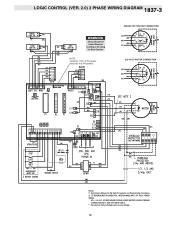
LOGIC CONTROL (VER. 2.0) 3 PHASE WIRING DIAGRAM 1837-3 380/460 VOLT MOTOR CONNECTION NOTE: Contactor 1 PH / 3 PH jumper should be in 3 PH position. 230 VOLT MOTOR CONNECTION Notes: 1) See Ownerʼs Manual for Dip Switch Functions and Programming Procedures 2) TO REVERSE MOTOR DIRECTION: INTERCHANGE ANY 2 OF THE 3 POWER WIRES AT L1, L2 & L3, OR EXCHANGE PURPLE & GRAY MOTOR LEADS AT BOARD CONNECTIONS E17 & E6 (3PH UNITS ONLY). **- Transformer Primary Voltage same as Line Voltage. 12
LOGIC CONTROL (VER. 2.0) 3 PHASE WIRING DIAGRAM 1837-3 380/460 VOLT MOTOR CONNECTION NOTE: Contactor 1 PH / 3 PH jumper should be in 3 PH position. 230 VOLT MOTOR CONNECTION Notes: 1) See Ownerʼs Manual for Dip Switch Functions and Programming Procedures 2) TO REVERSE MOTOR DIRECTION: INTERCHANGE ANY 2 OF THE 3 POWER WIRES AT L1, L2 & L3, OR EXCHANGE PURPLE & GRAY MOTOR LEADS AT BOARD CONNECTIONS E17 & E6 (3PH UNITS ONLY). **- Transformer Primary Voltage same as Line Voltage. 12
GH LOGIC VERSION 2 Manual
Page 13
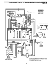
LOGIC CONTROL (VER. 2.0) 1 PH WIRING DIAGRAM W/ CONTACTOR1842-1 NOTE: Contactor 1 PH / 3 PH jumper should be in 1 PH position. 115 VOLT MOTOR CONNECTION Note: 1) See Ownerʼs Manual for Dip Switch Functions and Programming Procedures 2) TO REVERSE MOTOR DIRECTION 115 & 230 VOLTS: INTERCHANGE PURPLE & GRAY WIRES AT CONTACTOR. **- Transformer Primary Voltage same as Line Voltage. 13
LOGIC CONTROL (VER. 2.0) 1 PH WIRING DIAGRAM W/ CONTACTOR1842-1 NOTE: Contactor 1 PH / 3 PH jumper should be in 1 PH position. 115 VOLT MOTOR CONNECTION Note: 1) See Ownerʼs Manual for Dip Switch Functions and Programming Procedures 2) TO REVERSE MOTOR DIRECTION 115 & 230 VOLTS: INTERCHANGE PURPLE & GRAY WIRES AT CONTACTOR. **- Transformer Primary Voltage same as Line Voltage. 13
GH LOGIC 3 Manual
Page 1
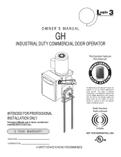
L 3 ogic OWNER'S MANUAL GH INDUSTRIAL DUTY COMMERCIAL DOOR OPERATOR This Operator Features the Enhanced INTENAN MA E M E C AL E PATENT PENDING R T T SYS The Maintenance Alert System™ allows the installer to ... 315MHz NOT FOR RESIDENTIAL USE Serial # Box Installation Date A SAFETY DEVICE IS HIGHLY RECOMMENDED The Logic 3 operator incorporates a self-diagnostic feature built into the (MAS) Maintenance Alert System LED. INTENDED FOR PROFESSIONAL INSTALLATION ONLY Visit www.LiftMaster.com to set number of cycles/ months is reached or when the operator requires immediate...
L 3 ogic OWNER'S MANUAL GH INDUSTRIAL DUTY COMMERCIAL DOOR OPERATOR This Operator Features the Enhanced INTENAN MA E M E C AL E PATENT PENDING R T T SYS The Maintenance Alert System™ allows the installer to ... 315MHz NOT FOR RESIDENTIAL USE Serial # Box Installation Date A SAFETY DEVICE IS HIGHLY RECOMMENDED The Logic 3 operator incorporates a self-diagnostic feature built into the (MAS) Maintenance Alert System LED. INTENDED FOR PROFESSIONAL INSTALLATION ONLY Visit www.LiftMaster.com to set number of cycles/ months is reached or when the operator requires immediate...
GH LOGIC 3 Manual
Page 2
...Specifications 4 PREPARATION Hand Chain Right/Left Conversion 5 Disconnect Lever Right/Left Conversion 5 Horizontal Mounting Conversion 5 INSTALLATION Mount the Operator 6 Manual Operation 7 Entrapment Protection Accessories 8 ADJUSTMENT Limit Switch Adjustment 8 Adjust Torque Limiter Clutch 9 Brake Adjustment 9 POWER & GROUND WIRING ... Standard Power & Control Connection Diagrams 12 1 Phase Wiring Diagram 13 3 Phase Wiring Diagram 14 Logic Board 15 PROGRAMMING Logic Control Pushbuttons 16 Determine and Set Wiring Type 16 Failsafe Wiring Types 17 Self-Monitoring Safety Device...
...Specifications 4 PREPARATION Hand Chain Right/Left Conversion 5 Disconnect Lever Right/Left Conversion 5 Horizontal Mounting Conversion 5 INSTALLATION Mount the Operator 6 Manual Operation 7 Entrapment Protection Accessories 8 ADJUSTMENT Limit Switch Adjustment 8 Adjust Torque Limiter Clutch 9 Brake Adjustment 9 POWER & GROUND WIRING ... Standard Power & Control Connection Diagrams 12 1 Phase Wiring Diagram 13 3 Phase Wiring Diagram 14 Logic Board 15 PROGRAMMING Logic Control Pushbuttons 16 Determine and Set Wiring Type 16 Failsafe Wiring Types 17 Self-Monitoring Safety Device...
GH LOGIC 3 Manual
Page 11
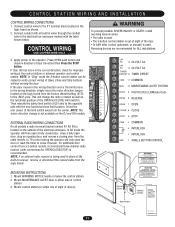
...control station is out of sight of the door. • Or ANY other control (automatic or manual) is used in receiver, remove or disconnect the coaxial cable from the factory default setting (STD)...TIMER DEFEAT 12 TIMER DEFEAT AVECRMN T1I1SCSOMEMMON ENT MAS 10 MAINTENANCE ALERT SYSTEM ATTENTION EYES 9 PHOTO EYES (LiftMaster Only) EDGE 8 REVERSE OPEN 7 OPEN CLOSE 6 CLOSE STOP 5 STOP CMN 4 COMMON 3 INTERLOCK ...door. Mount MAINTENANCE ALERT label to the P1 terminal block located on the logic board from the logic board. Connect conduit with the new functional close limit location. Mount WARNING...
...control station is out of sight of the door. • Or ANY other control (automatic or manual) is used in receiver, remove or disconnect the coaxial cable from the factory default setting (STD)...TIMER DEFEAT 12 TIMER DEFEAT AVECRMN T1I1SCSOMEMMON ENT MAS 10 MAINTENANCE ALERT SYSTEM ATTENTION EYES 9 PHOTO EYES (LiftMaster Only) EDGE 8 REVERSE OPEN 7 OPEN CLOSE 6 CLOSE STOP 5 STOP CMN 4 COMMON 3 INTERLOCK ...door. Mount MAINTENANCE ALERT label to the P1 terminal block located on the logic board from the logic board. Connect conduit with the new functional close limit location. Mount WARNING...
GH LOGIC 3 Manual
Page 18
...modes, operation is performed within 30 seconds. Press and release the SBC externally wired button or TIMER on the logic board (LED flashes rapidly and then remains on the logic board (LED will light). 2. Tested to Comply with Timer to CLOSE/STOP on solid after releasing the button.... supported with FCC and or Industry Canada (IC) rules, adjustment or modifications of the door. • Or ANY other control (automatic or manual) is enabled, SBC will then remain on release. WARNING To prevent possible SEVERE INJURY or DEATH, install reversing sensors whenC: AUTION • The...
...modes, operation is performed within 30 seconds. Press and release the SBC externally wired button or TIMER on the logic board (LED flashes rapidly and then remains on the logic board (LED will light). 2. Tested to Comply with Timer to CLOSE/STOP on solid after releasing the button.... supported with FCC and or Industry Canada (IC) rules, adjustment or modifications of the door. • Or ANY other control (automatic or manual) is enabled, SBC will then remain on release. WARNING To prevent possible SEVERE INJURY or DEATH, install reversing sensors whenC: AUTION • The...
GH Logic 4 Quick Start Guide Manual
Page 1
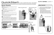
... door. Turn off power to highlight a typical installation. Electrical Interlock with a manual hoist. Connect the power to ensure that the total door system is safe for the model GH door operator IMPORTANT: This QuickStart is used. Turn off power to door shaft ... Operator 1b Bracket Shelf Mounted Operator OPTIONAL Mounting Bracket P/N 08-9098 Optimum Distance 12" - 15" Optimum Distance 12" - 15" LOGIC 4 Manual Operation This operator has provisions for further information. Operate the door in case of the purchaser, designer, installer and end user to the...
... door. Turn off power to highlight a typical installation. Electrical Interlock with a manual hoist. Connect the power to ensure that the total door system is safe for the model GH door operator IMPORTANT: This QuickStart is used. Turn off power to door shaft ... Operator 1b Bracket Shelf Mounted Operator OPTIONAL Mounting Bracket P/N 08-9098 Optimum Distance 12" - 15" Optimum Distance 12" - 15" LOGIC 4 Manual Operation This operator has provisions for further information. Operate the door in case of the purchaser, designer, installer and end user to the...


