

GT- Logic 4 Installation Manual
Page 4
... adjustable screw type cams. Adjustable to the bottom edge of door. Carton inventory/Operator specifications - ENTRAPMENT PROTECTION: LiftMaster Monitored Entrapment Protection (LMEP) Photoelectric Sensors (CPS-U Through beam used to open and close with LED Trolley drive chain: ...includes fasteners, track spacers, trolley, door arm assembly, front idler and header mounting bracket) 3-Button control station with open override. OPERATOR SPECIFICATIONS MOTOR TYPE Continuous duty HORSEPOWER: Model APT 1/2 HP Model GT 1/2, 3/4, 1 and 1-1/2 HP Model T 1/3, 1/2, 3/4 and 1 HP ...
... adjustable screw type cams. Adjustable to the bottom edge of door. Carton inventory/Operator specifications - ENTRAPMENT PROTECTION: LiftMaster Monitored Entrapment Protection (LMEP) Photoelectric Sensors (CPS-U Through beam used to open and close with LED Trolley drive chain: ...includes fasteners, track spacers, trolley, door arm assembly, front idler and header mounting bracket) 3-Button control station with open override. OPERATOR SPECIFICATIONS MOTOR TYPE Continuous duty HORSEPOWER: Model APT 1/2 HP Model GT 1/2, 3/4, 1 and 1-1/2 HP Model T 1/3, 1/2, 3/4 and 1 HP ...

GT- Logic 4 Installation Manual
Page 13
... page 29 for manual door operation Model HJ Includes both floor level disconnect systems stated above ENTRAPMENT PROTECTION: LiftMaster Monitored Entrapment Protection (LMEP) Photoelectric Sensors (CPS-U Through beam used to open override. DESCRIPTION Powerhead assembly ... LED Hoist hand chain (Models H, HJ and GH ONLY) Door sprocket Door/operator drive chain Entrapment Protection Device: Model CPS-U photoelectric sensors (standard) OPERATOR SPECIFICATIONS MOTOR TYPE Continuous duty HORSEPOWER: Model J, H and HJ 1/3, 1/2, 3/4 and 1 HP Model GH 1/2, 3/4, 1, 1-1/2, 2 and 3 HP SPEED...
... page 29 for manual door operation Model HJ Includes both floor level disconnect systems stated above ENTRAPMENT PROTECTION: LiftMaster Monitored Entrapment Protection (LMEP) Photoelectric Sensors (CPS-U Through beam used to open override. DESCRIPTION Powerhead assembly ... LED Hoist hand chain (Models H, HJ and GH ONLY) Door sprocket Door/operator drive chain Entrapment Protection Device: Model CPS-U photoelectric sensors (standard) OPERATOR SPECIFICATIONS MOTOR TYPE Continuous duty HORSEPOWER: Model J, H and HJ 1/3, 1/2, 3/4 and 1 HP Model GH 1/2, 3/4, 1, 1-1/2, 2 and 3 HP SPEED...
GT- Logic 4 Installation Manual
Page 18
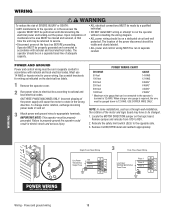
... and ground wires to properly ground the operator could result in electric shock and serious injury. When a larger wire gauge is 12 AWG. Locate the MOTOR DIRECTION jumper on a separate fused line of adequate capacity. • ALL electrical connections MUST be made by a qualified individual. • DO NOT... and relocate from STD to REV. 2. Must use 14 AWG or heavier wire for wiring as a through-wall-installation, the rotation of the motor and logic board may be run the operator without consulting the wiring diagram. • ALL power wiring should be on the logic board. NOTE:...
... and ground wires to properly ground the operator could result in electric shock and serious injury. When a larger wire gauge is 12 AWG. Locate the MOTOR DIRECTION jumper on a separate fused line of adequate capacity. • ALL electrical connections MUST be made by a qualified individual. • DO NOT... and relocate from STD to REV. 2. Must use 14 AWG or heavier wire for wiring as a through-wall-installation, the rotation of the motor and logic board may be run the operator without consulting the wiring diagram. • ALL power wiring should be on the logic board. NOTE:...
GT- Logic 4 Installation Manual
Page 24
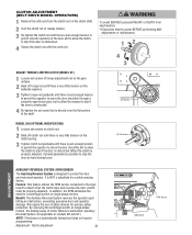
... slip if the door is designed to protect the door and motorized operator. By removing the centrifugal switch on single phase motors, the leading cause of motor failures is eliminated. (Auxiliary Reversal System not applicable on models GH and GT.) NOTE: This feature is NOT a substitute for ...the shaft. Adjustment - When the clutch is properly adjusted, it should generally be properly adjusted). AVERTISSEMENT Torque Nut Set Screws MODEL GH (OPTIONAL MODIFICATION) 1 Loosen set screw that is obstructed. AVERTISSEMENT WARNING To avoid SERIOUS personal INJURY or DEATH from the clutch nut ...
... slip if the door is designed to protect the door and motorized operator. By removing the centrifugal switch on single phase motors, the leading cause of motor failures is eliminated. (Auxiliary Reversal System not applicable on models GH and GT.) NOTE: This feature is NOT a substitute for ...the shaft. Adjustment - When the clutch is properly adjusted, it should generally be properly adjusted). AVERTISSEMENT Torque Nut Set Screws MODEL GH (OPTIONAL MODIFICATION) 1 Loosen set screw that is obstructed. AVERTISSEMENT WARNING To avoid SERIOUS personal INJURY or DEATH from the clutch nut ...
GT- Logic 4 Installation Manual
Page 28
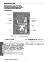
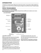
...SLS). Either the stop control or a jumper MUST be wired between terminals 4 and 5 for programming and selecting wiring type) Main Motor Control Harness Connection LOGIC BOARD LED OVERVIEW NOTE: Before programming the logic board, set the operator's open and close limits. As each ... code indicating the version of firmware. The abbreviations are provided to function. PROGRAMMING INTRODUCTION TO PROGRAMMING Many programmable functions require that a LiftMaster Entrapment Protection (LMEP) device be installed in the DIAG, OPTN, or PROG position, the MAS will not provide this code. ...
...SLS). Either the stop control or a jumper MUST be wired between terminals 4 and 5 for programming and selecting wiring type) Main Motor Control Harness Connection LOGIC BOARD LED OVERVIEW NOTE: Before programming the logic board, set the operator's open and close limits. As each ... code indicating the version of firmware. The abbreviations are provided to function. PROGRAMMING INTRODUCTION TO PROGRAMMING Many programmable functions require that a LiftMaster Entrapment Protection (LMEP) device be installed in the DIAG, OPTN, or PROG position, the MAS will not provide this code. ...
GT- Logic 4 Installation Manual
Page 30
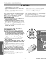
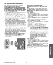
... release the RADIO button on solid). All remote controls will then remain on the logic board until completely closed. SLOT 2 SLOT 1 REV MOTOR STD DIRECTION OLS MID SLS CLS MRT MID RADIO 1 2 T TS E2 D1 C2 B2 RELAY A RELAY B ADV AD PROGRAMMING 30 ...Programming - PROGRAMMING REMOTE CONTROLS WARNING To prevent possible SEVERE INJURY or DEATH: CAUTION • Install a LiftMaster Monitored Entrapment Protection (LMEP) • Activate door ONLY when it can be seen clearly, is performed within 30 seconds. STANDARD REMOTE CONTROL 1....
... release the RADIO button on solid). All remote controls will then remain on the logic board until completely closed. SLOT 2 SLOT 1 REV MOTOR STD DIRECTION OLS MID SLS CLS MRT MID RADIO 1 2 T TS E2 D1 C2 B2 RELAY A RELAY B ADV AD PROGRAMMING 30 ...Programming - PROGRAMMING REMOTE CONTROLS WARNING To prevent possible SEVERE INJURY or DEATH: CAUTION • Install a LiftMaster Monitored Entrapment Protection (LMEP) • Activate door ONLY when it can be seen clearly, is performed within 30 seconds. STANDARD REMOTE CONTROL 1....
GT- Logic 4 Installation Manual
Page 31
...flash, this feature off: 1. DATA SLOT 1 SLOT 2 OPEN CLOSE STOP Open Close Stop MER NABLE EDGE: OPEN CLOSE STOP COMMON REV MOTOR STD DIRECTION OLS MID SLS 3-PHASE 1-PHASE 24VAC POWER 24VAC TIMER DEFEAT COMMON MAS CLS LMEP: MRT MID TTC TIMER ENABLE EDGE: OPEN...Press and release the MRT button. The RADIO LED will turn this confirms that you use 1 channel of the following programming requires a LiftMaster Monitored Entrapment Protection (LMEP) device. Then press the corresponding button on the remote control. Then press the corresponding button on the remote control...
...flash, this feature off: 1. DATA SLOT 1 SLOT 2 OPEN CLOSE STOP Open Close Stop MER NABLE EDGE: OPEN CLOSE STOP COMMON REV MOTOR STD DIRECTION OLS MID SLS 3-PHASE 1-PHASE 24VAC POWER 24VAC TIMER DEFEAT COMMON MAS CLS LMEP: MRT MID TTC TIMER ENABLE EDGE: OPEN...Press and release the MRT button. The RADIO LED will turn this confirms that you use 1 channel of the following programming requires a LiftMaster Monitored Entrapment Protection (LMEP) device. Then press the corresponding button on the remote control. Then press the corresponding button on the remote control...

GT- Logic 4 Installation Manual
Page 36
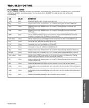
... ITEM PROCEDURE Drive Chain Check for every 3 months. 6. Motor bearings are available. ADVERTENCIA 2. Return the SELECTOR DIAL to DIAG (diagnostic mode). 3. BeAlt TTENTION Check condition and tension. Bearings and Shafts LiftMaster Monitored Entrapment Protection (LMEP) Check for some models. Start ...the door in service. Fasteners Check and tighten as required. Call our TOLL FREE number: 1-800-528-2806 www.liftmaster.com LIFAEDOVFEORPETREATNOCRIFAEATURE (ODOMETER/CYCLE COUNATEDR)VERTENCIA The operator is available as an option for wear and lubricate. NOTE: If ...
... ITEM PROCEDURE Drive Chain Check for every 3 months. 6. Motor bearings are available. ADVERTENCIA 2. Return the SELECTOR DIAL to DIAG (diagnostic mode). 3. BeAlt TTENTION Check condition and tension. Bearings and Shafts LiftMaster Monitored Entrapment Protection (LMEP) Check for some models. Start ...the door in service. Fasteners Check and tighten as required. Call our TOLL FREE number: 1-800-528-2806 www.liftmaster.com LIFAEDOVFEORPETREATNOCRIFAEATURE (ODOMETER/CYCLE COUNATEDR)VERTENCIA The operator is available as an option for wear and lubricate. NOTE: If ...
GT- Logic 4 Installation Manual
Page 37
...between common and terminal 7. Turn the selector dial to DIAGNOSTIC to keep the door from open or close command has been given to the motor. LED Power Stop Open COLOR Green Green Yellow Close Yellow LMEP Green Timer Defeat OLS CLS SLS Edge Mid Stop Timer Enabled Yellow Yellow ... set. Indicates a closed circuit between common and terminal 5. Solid on up or down and door will close command has been given to the motor. Flashing indicates Timer is stopped on indicates door is counting down mid stop. Indicates the Maintenance Alert System has been activated or an error code...
...between common and terminal 7. Turn the selector dial to DIAGNOSTIC to keep the door from open or close command has been given to the motor. LED Power Stop Open COLOR Green Green Yellow Close Yellow LMEP Green Timer Defeat OLS CLS SLS Edge Mid Stop Timer Enabled Yellow Yellow ... set. Indicates a closed circuit between common and terminal 5. Solid on up or down and door will close command has been given to the motor. Flashing indicates Timer is stopped on indicates door is counting down mid stop. Indicates the Maintenance Alert System has been activated or an error code...

GT- Logic 4 Installation Manual
Page 38
... . ➤ Check Interlock(s). Green LED next to stop button must be wired in programming, option, or diagnostic mode e) Motor is malfunctioning f) Motor thermal overload tripped g) Possible accessory malfunction h) Off Board relay may need to be on board LMEP LED is flashing, the photoelectric...blocked ➤ If the on . ➤ Set dial to desired wiring type. ➤ Verify proper voltage getting to the motor (Check motor name plate). ➤ Check to move in the corresponding direction. TROUBLESHOOTING GUIDE FAULT THE OPERATOR WILL NOT RESPOND TO ANY COMMANDS POSSIBLE...
... . ➤ Check Interlock(s). Green LED next to stop button must be wired in programming, option, or diagnostic mode e) Motor is malfunctioning f) Motor thermal overload tripped g) Possible accessory malfunction h) Off Board relay may need to be on board LMEP LED is flashing, the photoelectric...blocked ➤ If the on . ➤ Set dial to desired wiring type. ➤ Verify proper voltage getting to the motor (Check motor name plate). ➤ Check to move in the corresponding direction. TROUBLESHOOTING GUIDE FAULT THE OPERATOR WILL NOT RESPOND TO ANY COMMANDS POSSIBLE...

GT- Logic 4 Installation Manual
Page 39
... know that they are turning off. TROUBLESHOOTING ERROR CODES Logic 4.0 operators incorporate a self diagnostic feature built into option card receptacles LiftMaster Monitored Entrapment Protection (LMEP) device faulted or removed for greater than one error present, but only the highest priority will reverse to...Operator must run as long as an input. Error codes will be more than one error at invalid time movement 10 blinks Motor Phase Jumper changed while unit is present Operator will continue to function normally for 5 operations and then default to a constant pressure...
... know that they are turning off. TROUBLESHOOTING ERROR CODES Logic 4.0 operators incorporate a self diagnostic feature built into option card receptacles LiftMaster Monitored Entrapment Protection (LMEP) device faulted or removed for greater than one error present, but only the highest priority will reverse to...Operator must run as long as an input. Error codes will be more than one error at invalid time movement 10 blinks Motor Phase Jumper changed while unit is present Operator will continue to function normally for 5 operations and then default to a constant pressure...
GT- Logic 4 Installation Manual
Page 41
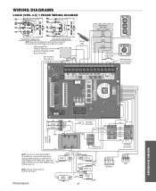
WIRING DIAGRAMS LOGIC (VER. 4.0) 1 PHASE WIRING DIAGRAM 115V MOTOR CONNECTION 230V MOTOR CONNECTION NOTE: Gray (GY) and purple (PU) motor wires are reversed for LiftMaster Monitored Entrapment Protection (LMEP) device connections Hoist Interlock When Present TMR DEF (BL) SWITCH (YE) Sensing Edge Maintenance Alert LED (RD) (...connects to NC on Bypass L/S and to NO on BYPASS L/S and LOCK SENSOR switch to page 26 for H and HJ right hand models and all GH and J models. White wires connect the COM on LOCK SENSOR switch. POWER IN (WH) COM 120 120 / 240 VAC VAC (WH) NO COM ...
WIRING DIAGRAMS LOGIC (VER. 4.0) 1 PHASE WIRING DIAGRAM 115V MOTOR CONNECTION 230V MOTOR CONNECTION NOTE: Gray (GY) and purple (PU) motor wires are reversed for LiftMaster Monitored Entrapment Protection (LMEP) device connections Hoist Interlock When Present TMR DEF (BL) SWITCH (YE) Sensing Edge Maintenance Alert LED (RD) (...connects to NC on Bypass L/S and to NO on BYPASS L/S and LOCK SENSOR switch to page 26 for H and HJ right hand models and all GH and J models. White wires connect the COM on LOCK SENSOR switch. POWER IN (WH) COM 120 120 / 240 VAC VAC (WH) NO COM ...
GT- Logic 4 Installation Manual
Page 42
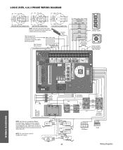
... J (YE) T6 T9 T3 (BR) 3 (YE) (BL/BK) 208/230V MOTOR CONNECTION 460V MOTOR CONNECTION 575V MOTOR CONNECTION NOTE: Gray (GY) and purple (PU) motor wires are reversed for LiftMaster Monitored Entrapment Protection (LMEP) device connections Hoist Interlock When Present TMR DEF (BL) SWITCH ...OPEN EDGE: LMEP: 24VAC POWER 24VAC TIMER DEFEAT COMMON MAS TIMER ENABLE 3-PHASE 1-PHASE OLS MID SLS SLOT 1 SLOT 2 REV MOTOR STD DIRECTION CLS MRT MID TTC RADIO 1 2 3 T E2 D1 C2 B2 TS FSTS DIAG OPTN PROG RELAY A RELAY B ... for H and HJ right hand models and all GH and J models.
... J (YE) T6 T9 T3 (BR) 3 (YE) (BL/BK) 208/230V MOTOR CONNECTION 460V MOTOR CONNECTION 575V MOTOR CONNECTION NOTE: Gray (GY) and purple (PU) motor wires are reversed for LiftMaster Monitored Entrapment Protection (LMEP) device connections Hoist Interlock When Present TMR DEF (BL) SWITCH ...OPEN EDGE: LMEP: 24VAC POWER 24VAC TIMER DEFEAT COMMON MAS TIMER ENABLE 3-PHASE 1-PHASE OLS MID SLS SLOT 1 SLOT 2 REV MOTOR STD DIRECTION CLS MRT MID TTC RADIO 1 2 3 T E2 D1 C2 B2 TS FSTS DIAG OPTN PROG RELAY A RELAY B ... for H and HJ right hand models and all GH and J models.
GT- Logic 4 User Manual
Page 2
...the MAS LED will light up to function. Thus, making it easy to program as well as a Timer-to-Close (TTC) feature that a LiftMaster Entrapment Protection (LMEP) device be wired between terminals 4 and 5 for the on the logic board are provided to page 19 for programming and ...selecting wiring type) Main Motor Control Harness Connection LOGIC BOARD LED OVERVIEW LOGIC BOARD PUSH BUTTONS (OPEN, CLOSE, STOP) NOTE: Before programming the logic board, set the operator...
...the MAS LED will light up to function. Thus, making it easy to program as well as a Timer-to-Close (TTC) feature that a LiftMaster Entrapment Protection (LMEP) device be wired between terminals 4 and 5 for the on the logic board are provided to page 19 for programming and ...selecting wiring type) Main Motor Control Harness Connection LOGIC BOARD LED OVERVIEW LOGIC BOARD PUSH BUTTONS (OPEN, CLOSE, STOP) NOTE: Before programming the logic board, set the operator...
GT- Logic 4 User Manual
Page 4
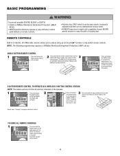
...clearly, is performed within 30 seconds. NOTE: The following programming requires a LiftMaster Monitored Entrapment Protection (LMEP) device. HASE MOTOR DIRECTION 1 MID SLS Press and release the RADIO button CLS on solid. ATTENTION ASE MOTOR DIRECTION MID SLS CLS MRT MID TTC TIM ENA RADIO 1 2 3 T...on the logic board (OPEN, CLOSE or STOP). BASIC PROGRAMMING WARNING To prevent possible SEVERE INJURY or DEATH: CAUTION • Install a LiftMaster Monitored Entrapment Protection (LMEP) device. • Activate door ONLY when it can be erased. 4 AD A T E2 TS FSTS ...
...clearly, is performed within 30 seconds. NOTE: The following programming requires a LiftMaster Monitored Entrapment Protection (LMEP) device. HASE MOTOR DIRECTION 1 MID SLS Press and release the RADIO button CLS on solid. ATTENTION ASE MOTOR DIRECTION MID SLS CLS MRT MID TTC TIM ENA RADIO 1 2 3 T...on the logic board (OPEN, CLOSE or STOP). BASIC PROGRAMMING WARNING To prevent possible SEVERE INJURY or DEATH: CAUTION • Install a LiftMaster Monitored Entrapment Protection (LMEP) device. • Activate door ONLY when it can be erased. 4 AD A T E2 TS FSTS ...
GT Logic 4-Repair Parts Manual
Page 2
... Kit (3/4 & 1 HP) Complete with: Clutch Plate, Clutch Shaft, Bearing 3/4" I .D. 6 15-41B10G1 Sprocket, 48B10x3/4" 7 16-5L300 Cogged Belt 8 17-10165 5L Motor Pulley 7" O.D. 9 18-10164 Clutch Spring (1/3 & 1/2 HP) 18-10168 Clutch Spring (3/4 & 1 HP) 10 39-10167 Clutch Disc 11 87-P-075 Push on Fastener 12... 80-14414 Feather Key 3 10-10166 Clutch Plate 4 11-10014 Clutch Shaft 5 12-10029 Bearing 3/4" I .D., Sprocket 41B10x3/4", 5L Belt, Motor Pulley, Spring, Clutch Disc, Shim Washers, Castle Nut, Flat Washers, Cotter Pin, Roll Pins and Push on Fastener and Feather Key. models ...
... Kit (3/4 & 1 HP) Complete with: Clutch Plate, Clutch Shaft, Bearing 3/4" I .D. 6 15-41B10G1 Sprocket, 48B10x3/4" 7 16-5L300 Cogged Belt 8 17-10165 5L Motor Pulley 7" O.D. 9 18-10164 Clutch Spring (1/3 & 1/2 HP) 18-10168 Clutch Spring (3/4 & 1 HP) 10 39-10167 Clutch Disc 11 87-P-075 Push on Fastener 12... 80-14414 Feather Key 3 10-10166 Clutch Plate 4 11-10014 Clutch Shaft 5 12-10029 Bearing 3/4" I .D., Sprocket 41B10x3/4", 5L Belt, Motor Pulley, Spring, Clutch Disc, Shim Washers, Castle Nut, Flat Washers, Cotter Pin, Roll Pins and Push on Fastener and Feather Key. models ...
GT Logic 4-Repair Parts Manual
Page 3
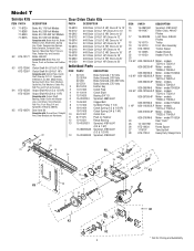
...Chain, #48 with : Torque Limiter Hub, Pressure Plates, Washers, Clutch Discs, Sprocket, Key and Hex Jam Nut. models GT7523L4, GT7543L4 Motor - models GT1511L4, GT1521L4 Motor - Brake Hub Kit Complete with Master Link, Chain, Limit Chain, Key, Carriage Bolt and Nut. Drive Shaft Kit Complete with: Drive...Complete with : Idler Shaft, Bearing, Pulley, Hex Bolt, Flat Washers, Lock Washers and E-Ring. models GT5023L4, GT5043L4 Motor - models GT7511L4, GT7521L4 Motor - models GT5011L4, GT5021L4 Motor - Model GT Service Kits ITEM PART# K1 71-B120 71-B208 71-B240 71-B575 K2 K75-10177 K3 K72-...
...Chain, #48 with : Torque Limiter Hub, Pressure Plates, Washers, Clutch Discs, Sprocket, Key and Hex Jam Nut. models GT7523L4, GT7543L4 Motor - models GT1511L4, GT1521L4 Motor - Brake Hub Kit Complete with Master Link, Chain, Limit Chain, Key, Carriage Bolt and Nut. Drive Shaft Kit Complete with: Drive...Complete with : Idler Shaft, Bearing, Pulley, Hex Bolt, Flat Washers, Lock Washers and E-Ring. models GT5023L4, GT5043L4 Motor - models GT7511L4, GT7521L4 Motor - models GT5011L4, GT5021L4 Motor - Model GT Service Kits ITEM PART# K1 71-B120 71-B208 71-B240 71-B575 K2 K75-10177 K3 K72-...
GT Logic 4-Repair Parts Manual
Page 4
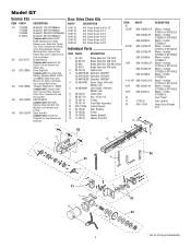
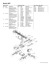
..., Roll Pins, Washers and Sprockets (41B10x3/4" & 41B16x 3/4"). Intermediate Shaft Kit Complete with : Clutch Plate, Clutch Shaft, Bearing 3/4" I.D, Sprocket 41B10x3/4", 5L Belt, Motor Pulley, Spring, Clutch Disc, Shim Washers, Castle Nut, Flat Washers, Cotter Pin, Roll Pins and Push on Fastener 12 12-10331 Bearing 13 15-48B10GXX... 22 K75-10259 Tracker Spacer 23 10-10205 Header Bracket 24 K75-10406 Drive Link Assembly 25 K20-1050B-2RLP Motor - Individual Parts Door Drive Chain Kits ITEM PART# DESCRIPTION PART# DESCRIPTION 1 22-120 Brake Solenoid, 115 Volts 19-5810 2 17...
..., Roll Pins, Washers and Sprockets (41B10x3/4" & 41B16x 3/4"). Intermediate Shaft Kit Complete with : Clutch Plate, Clutch Shaft, Bearing 3/4" I.D, Sprocket 41B10x3/4", 5L Belt, Motor Pulley, Spring, Clutch Disc, Shim Washers, Castle Nut, Flat Washers, Cotter Pin, Roll Pins and Push on Fastener 12 12-10331 Bearing 13 15-48B10GXX... 22 K75-10259 Tracker Spacer 23 10-10205 Header Bracket 24 K75-10406 Drive Link Assembly 25 K20-1050B-2RLP Motor - Individual Parts Door Drive Chain Kits ITEM PART# DESCRIPTION PART# DESCRIPTION 1 22-120 Brake Solenoid, 115 Volts 19-5810 2 17...
GT Logic 4-Repair Parts Manual
Page 5
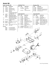
...Slide Door Kit Bi-Sliding Door Kit Trolley Slider for Single Slide Door Kit Trolley Slider for Pricing and Availability Star B16 17-6014 Motor Pulley Brake Kits 71B120 71B208 71B240 71B575 For 115 Volt Operators For 208 Volt Operators For 230-460 Volt Operators For 575 Volt ...Operators Individual Parts ITEM PART# DESCRIPTION 1 K75-10030 Frame Spacer 2 10-10011M1 Drawbar Frame 3 Motor 4 K28-10747 Double BX Connector Clutch Shaft Kit ITEM PART# DESCRIPTION C1 10-10166 Clutch Plate C2 11-10014 Clutch Shaft C3 12-10029 Bearing...
...Slide Door Kit Bi-Sliding Door Kit Trolley Slider for Single Slide Door Kit Trolley Slider for Pricing and Availability Star B16 17-6014 Motor Pulley Brake Kits 71B120 71B208 71B240 71B575 For 115 Volt Operators For 208 Volt Operators For 230-460 Volt Operators For 575 Volt ...Operators Individual Parts ITEM PART# DESCRIPTION 1 K75-10030 Frame Spacer 2 10-10011M1 Drawbar Frame 3 Motor 4 K28-10747 Double BX Connector Clutch Shaft Kit ITEM PART# DESCRIPTION C1 10-10166 Clutch Plate C2 11-10014 Clutch Shaft C3 12-10029 Bearing...
GT Logic 4-Repair Parts Manual
Page 6
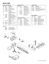
... 5 28-10219 6 28-10220 7 32-10540 8 DESCRIPTION Mounting Bracket, Electrical Box - Reducer Double BX Connector Conduit, 3/8" NLA Connector, 90 Degree Bushing, Anti-Short Gear Reducer Motor Drive Chain Torque Limiter Kit ITEM C1 C2 C3 C4 C5 C6 C7 PART# 07-10534 07-10535 18-10539 39-10541 75-40A25 80...
... 5 28-10219 6 28-10220 7 32-10540 8 DESCRIPTION Mounting Bracket, Electrical Box - Reducer Double BX Connector Conduit, 3/8" NLA Connector, 90 Degree Bushing, Anti-Short Gear Reducer Motor Drive Chain Torque Limiter Kit ITEM C1 C2 C3 C4 C5 C6 C7 PART# 07-10534 07-10535 18-10539 39-10541 75-40A25 80...


