
GT- Logic 4 Installation Manual
Page 20
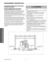
... its invisible light beam. Right Side of Garage- ENTWRAAPRMNEINNGT PROTECTION WARNING LPIRFOTTCMEAACSTUTIEOTRNIOM(LONMNEIPT)ORED ENTRAPMENT IMPORTANT INFORMATION ABOUT THE LIFTMASTER MONITORED ENTRAPMENT PROTECTION DEVICES A LiftMaster Monitored Entrapment Protection (LMEP) device is properly connected and aligned. If a LiftMaster Monitored Entrapment Protection device is being used on a vertically moving door, then place one or more edge sensors...
... its invisible light beam. Right Side of Garage- ENTWRAAPRMNEINNGT PROTECTION WARNING LPIRFOTTCMEAACSTUTIEOTRNIOM(LONMNEIPT)ORED ENTRAPMENT IMPORTANT INFORMATION ABOUT THE LIFTMASTER MONITORED ENTRAPMENT PROTECTION DEVICES A LiftMaster Monitored Entrapment Protection (LMEP) device is properly connected and aligned. If a LiftMaster Monitored Entrapment Protection device is being used on a vertically moving door, then place one or more edge sensors...
GT- Logic 4 Installation Manual
Page 21
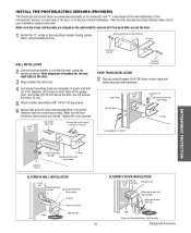
... surface. Inside Wall Lag Screws 1/4x1-1/2" Carriage Bolts (with 1/4"x1-1/2" lag screws. 6 Adjust right and left and right sides of the door. 3 Finger tighten the lock nuts. 4 Use bracket mounting holes as a template to locate and drill (2) 3/16" diameter pilot holes on both...Bracket with Square Holes "C" Wrap Lock Nuts #10-32 WALL INSTALLATION 2 Connect each side of the garage door, 4-6 inches (10-15 cm) above the floor. Drill 3/8" holes in each other across the door. 1 Fasten the "C" wraps to a slotted bracket, using hardware shown. Make sure the wraps and ...
... surface. Inside Wall Lag Screws 1/4x1-1/2" Carriage Bolts (with 1/4"x1-1/2" lag screws. 6 Adjust right and left and right sides of the door. 3 Finger tighten the lock nuts. 4 Use bracket mounting holes as a template to locate and drill (2) 3/16" diameter pilot holes on both...Bracket with Square Holes "C" Wrap Lock Nuts #10-32 WALL INSTALLATION 2 Connect each side of the garage door, 4-6 inches (10-15 cm) above the floor. Drill 3/8" holes in each other across the door. 1 Fasten the "C" wraps to a slotted bracket, using hardware shown. Make sure the wraps and ...
GH LOGIC 3 Manual
Page 22
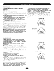
...TIMER SET LED will turn the selector dial to Diagnostic and press the TIMER button. To deactivate the timer for the door to close 15 seconds after a truck enters a garage. All timer modes require a supervised safety device to the desired wiring type (TS or T). This turns on the Car...truck to pass. (An internal stop position. 5. PROGRAMMING TIMER TO CLOSE PROGRAM TIMER TO CLOSE BY EXAMPLE (Method 2): To Program: 1. Close the door. 2. Wait for every 60 seconds programmed. The OPEN LED will flash once for every 5 seconds programmed and the CLOSE LED will flash 3 times ...
...TIMER SET LED will turn the selector dial to Diagnostic and press the TIMER button. To deactivate the timer for the door to close 15 seconds after a truck enters a garage. All timer modes require a supervised safety device to the desired wiring type (TS or T). This turns on the Car...truck to pass. (An internal stop position. 5. PROGRAMMING TIMER TO CLOSE PROGRAM TIMER TO CLOSE BY EXAMPLE (Method 2): To Program: 1. Close the door. 2. Wait for every 60 seconds programmed. The OPEN LED will flash once for every 5 seconds programmed and the CLOSE LED will flash 3 times ...


