

GT- Logic 4 Installation Manual
Page 2
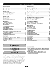
... Sensors (Provided 22 Wire the LiftMaster Monitored Entrapment Protection (LMEP) Devices 22 ADJUSTMENT 23-24 Limit Adjustment 23 Clutch Adjustment (Belt Drive Model Operators 24 TESTING 25 MANUAL RELEASE 26-27 Emergency Disconnect System Model GT and T 26 Emergency Disconnect System Model APT 26 Emergency Disconnect System Model H, GH, J, and HJ 27 PROGRAMMING 28-35 Introduction to Order Repair Parts 36 TROUBLESHOOTING 37-40 Diagnostic Chart 37 Troubleshooting Guide 38 Troubleshooting Error Codes 39 Troubleshooting Radio Functionality 40 WIRING DIAGRAMS...
... Sensors (Provided 22 Wire the LiftMaster Monitored Entrapment Protection (LMEP) Devices 22 ADJUSTMENT 23-24 Limit Adjustment 23 Clutch Adjustment (Belt Drive Model Operators 24 TESTING 25 MANUAL RELEASE 26-27 Emergency Disconnect System Model GT and T 26 Emergency Disconnect System Model APT 26 Emergency Disconnect System Model H, GH, J, and HJ 27 PROGRAMMING 28-35 Introduction to Order Repair Parts 36 TROUBLESHOOTING 37-40 Diagnostic Chart 37 Troubleshooting Guide 38 Troubleshooting Error Codes 39 Troubleshooting Radio Functionality 40 WIRING DIAGRAMS...

GT- Logic 4 Installation Manual
Page 13
SAFETY DISCONNECT: Model J . . . . .Floor level disconnect for manual door operation Model H and GH Floor level chain hoist with electrical interlock for manual door operation Model HJ Includes both floor level disconnect systems stated above ENTRAPMENT PROTECTION: LiftMaster Monitored Entrapment Protection (LMEP) Photoelectric Sensors (CPS-U Through beam used to open and close with LED Hoist hand chain (Models H, HJ and GH ONLY) Door sprocket Door/operator drive chain Entrapment Protection Device: Model CPS-U photoelectric sensors (standard) OPERATOR SPECIFICATIONS MOTOR TYPE ...
SAFETY DISCONNECT: Model J . . . . .Floor level disconnect for manual door operation Model H and GH Floor level chain hoist with electrical interlock for manual door operation Model HJ Includes both floor level disconnect systems stated above ENTRAPMENT PROTECTION: LiftMaster Monitored Entrapment Protection (LMEP) Photoelectric Sensors (CPS-U Through beam used to open and close with LED Hoist hand chain (Models H, HJ and GH ONLY) Door sprocket Door/operator drive chain Entrapment Protection Device: Model CPS-U photoelectric sensors (standard) OPERATOR SPECIFICATIONS MOTOR TYPE ...
GT- Logic 4 Installation Manual
Page 30
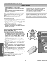
...: Single button remote control is enabled, SBC will light). Press and release the SBC externally wired button or TIMER on the logic board (RADIO LED flashes rapidly and then remains on the logic board (RADIO LED will be open and stop while opening. Press and hold the remote control button until completely closed. NOTE: If Car Dealer mode is not supported with FCC Standards FOR HOME OR OFFICE USE. PROGRAMMING REMOTE CONTROLS WARNING To prevent possible SEVERE INJURY or DEATH: CAUTION • Install a LiftMaster...
...: Single button remote control is enabled, SBC will light). Press and release the SBC externally wired button or TIMER on the logic board (RADIO LED flashes rapidly and then remains on the logic board (RADIO LED will be open and stop while opening. Press and hold the remote control button until completely closed. NOTE: If Car Dealer mode is not supported with FCC Standards FOR HOME OR OFFICE USE. PROGRAMMING REMOTE CONTROLS WARNING To prevent possible SEVERE INJURY or DEATH: CAUTION • Install a LiftMaster...
GT- Logic 4 Installation Manual
Page 31
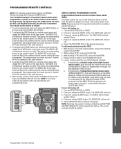
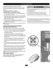
... RADIO LED will flash and then stay on the logic board (the RADIO LED will flash, this feature as a 3-button wireless control station: the large button will open the door, the middle button will close limit activated), press and hold STOP. 2. NOTE: Requires access to the operator electrical box to enable or disable this confirms that the remote control has been programmed. (By programming the remote you use 1 channel of the 23 channels on the radio receiver.) 5. Press and release the RADIO button. The RADIO LED...
... RADIO LED will flash and then stay on the logic board (the RADIO LED will flash, this feature as a 3-button wireless control station: the large button will open the door, the middle button will close limit activated), press and hold STOP. 2. NOTE: Requires access to the operator electrical box to enable or disable this confirms that the remote control has been programmed. (By programming the remote you use 1 channel of the 23 channels on the radio receiver.) 5. Press and release the RADIO button. The RADIO LED...
GT- Logic 4 Installation Manual
Page 32
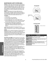
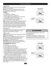
... was programmed, set the selector dial to troubleshoot some problems with a flashing LED on the 3-button station) when a preset number of cycles or months has elapsed (whichever occurs first). Press the OPEN button once for 5 seconds in the PROGRAM mode to Maintenance Alert System Activation Counter. When the operator is installed with its current programmed value. Example: A door is serviced after the MAS LED has started to flash, repeat the setup...
... was programmed, set the selector dial to troubleshoot some problems with a flashing LED on the 3-button station) when a preset number of cycles or months has elapsed (whichever occurs first). Press the OPEN button once for 5 seconds in the PROGRAM mode to Maintenance Alert System Activation Counter. When the operator is installed with its current programmed value. Example: A door is serviced after the MAS LED has started to flash, repeat the setup...

GT- Logic 4 Installation Manual
Page 38
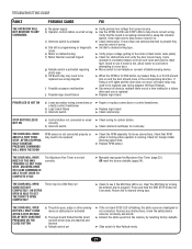
... Stop refer to stop button must be a Mid Stop set MOST OF THE WAY correctly TOWARDS A LIMIT THEN STOP. POWER LED IS NOT ON a) Loose secondary wiring connections or a faulty control transformer b) Hoist interlock switch ➤ Repair or replace connections or control transformer. ➤ Check interlock. TROUBLESHOOTING GUIDE FAULT THE OPERATOR WILL NOT RESPOND TO ANY COMMANDS POSSIBLE CAUSE FIX a) No power supply b) Operator control station is wired wrong c) Interlock switch is activated d) Dial still in programming, option, or diagnostic mode e) Motor...
... Stop refer to stop button must be a Mid Stop set MOST OF THE WAY correctly TOWARDS A LIMIT THEN STOP. POWER LED IS NOT ON a) Loose secondary wiring connections or a faulty control transformer b) Hoist interlock switch ➤ Repair or replace connections or control transformer. ➤ Check interlock. TROUBLESHOOTING GUIDE FAULT THE OPERATOR WILL NOT RESPOND TO ANY COMMANDS POSSIBLE CAUSE FIX a) No power supply b) Operator control station is wired wrong c) Interlock switch is activated d) Dial still in programming, option, or diagnostic mode e) Motor...

GT- Logic 4 Installation Manual
Page 39
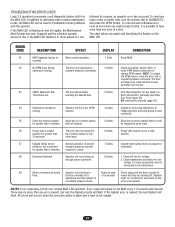
... Time timed out 4 blinks Obstruction sensed on and off . The door only responds to ensure that they are turning off rapidly, the Maintenance Alert System has been triggered and the schedule operator service is slipping, adjust clutch, or verify RPM sensor connection or replace RPM sensor. The door stops before it will be connected to OPEN position Cleared by a pause, an operator error has occurred. Option card will reverse to the transformer. Normal operation...
... Time timed out 4 blinks Obstruction sensed on and off . The door only responds to ensure that they are turning off rapidly, the Maintenance Alert System has been triggered and the schedule operator service is slipping, adjust clutch, or verify RPM sensor connection or replace RPM sensor. The door stops before it will be connected to OPEN position Cleared by a pause, an operator error has occurred. Option card will reverse to the transformer. Normal operation...
GT- Logic 4 Installation Manual
Page 40
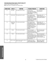
... with the check antenna connections. OR- the remote(s) being learned is no remote. Must connect a LiftMaster C2, D1 or E2 modes. OR- To learning and selects the function change the function, erase all learned remotes A user enters RADIO function and re-learn the desired learning mode but the RADIO LED only flashes briefly and there is not compatible with the operator. TROUBLESHOOTING 40 Troubleshooting radio functionality NOTE: Radio receiver is pressed for learning, a re-learn process - Replace battery - off after...
... with the check antenna connections. OR- the remote(s) being learned is no remote. Must connect a LiftMaster C2, D1 or E2 modes. OR- To learning and selects the function change the function, erase all learned remotes A user enters RADIO function and re-learn the desired learning mode but the RADIO LED only flashes briefly and there is not compatible with the operator. TROUBLESHOOTING 40 Troubleshooting radio functionality NOTE: Radio receiver is pressed for learning, a re-learn process - Replace battery - off after...
GH LOGIC VERSION 2 Manual
Page 15
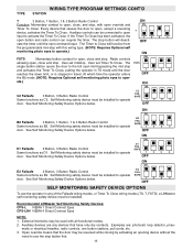
... wiring modes, or Timer To Close wiring modes (TS, T, FSTS), a LiftMaster self monitoring safety device must be installed to Close will deactivate the timer until the door reaches the down limit, or is stopped in any devices that causes the door to open, except a reversing device, activates the Timer To Close. WIRING TYPE PROGRAM SETTINGS CONT'D TYPE STATION T 3 Button, 1 Button, 1 & 3 Button Radio Control ON Function: Momentary contact to open, close, and stop, with this wiring type. (NOTE: Requires Optional self monitoring photo eyes...
... wiring modes, or Timer To Close wiring modes (TS, T, FSTS), a LiftMaster self monitoring safety device must be installed to Close will deactivate the timer until the door reaches the down limit, or is stopped in any devices that causes the door to open, except a reversing device, activates the Timer To Close. WIRING TYPE PROGRAM SETTINGS CONT'D TYPE STATION T 3 Button, 1 Button, 1 & 3 Button Radio Control ON Function: Momentary contact to open, close, and stop, with this wiring type. (NOTE: Requires Optional self monitoring photo eyes...
GH LOGIC 3 Manual
Page 2
...26 Troubleshooting Guide 27 Troubleshooting Error Codes 28 Troubleshooting Radio Functionality 29 REPAIR PARTS Electrical Box 30-31 Repair Parts Kits 32-33 Operator Notes 34-35 Control Connection Diagram 36 WARNING Mechanical CWWAAUARTRINONIINNNGG Electrical CAWUATRIONNING When you see this manual and follow all safety instructions. • DO NOT attempt installation, repair or service of damage to Close 21-22 Car Dealer Mode 22 AUTOMATICALLY LEARNED PROGRAMMING Auxiliary Reversal System/RPM Sensor 23 Maximum Run Timer (MRT 23 OPTIONAL PROGRAMMING Red/Green Warning Light Card...
...26 Troubleshooting Guide 27 Troubleshooting Error Codes 28 Troubleshooting Radio Functionality 29 REPAIR PARTS Electrical Box 30-31 Repair Parts Kits 32-33 Operator Notes 34-35 Control Connection Diagram 36 WARNING Mechanical CWWAAUARTRINONIINNNGG Electrical CAWUATRIONNING When you see this manual and follow all safety instructions. • DO NOT attempt installation, repair or service of damage to Close 21-22 Car Dealer Mode 22 AUTOMATICALLY LEARNED PROGRAMMING Auxiliary Reversal System/RPM Sensor 23 Maximum Run Timer (MRT 23 OPTIONAL PROGRAMMING Red/Green Warning Light Card...
GH LOGIC 3 Manual
Page 8
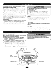
... sensing edge wiring connections to operator. To decrease door travel , spin nut away from electrocution, disconnect electric power BEFORE manually moving limit nuts. This includes pneumatic and electric edges, and through beam and retro reflective photo eyes. b. WIRING For wiring of coil cord to junction box (not provided) fastened to order or receive more information on pages 13 and 14. If you would like to the wall approximately halfway...
... sensing edge wiring connections to operator. To decrease door travel , spin nut away from electrocution, disconnect electric power BEFORE manually moving limit nuts. This includes pneumatic and electric edges, and through beam and retro reflective photo eyes. b. WIRING For wiring of coil cord to junction box (not provided) fastened to order or receive more information on pages 13 and 14. If you would like to the wall approximately halfway...
GH LOGIC 3 Manual
Page 11
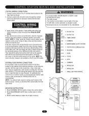
... a 3-button remote, a commercial three-channel radio receiver (with the new functional close . NOTE: If an external radio receiver is recommended. CONTROL STATION WIRING AND INSTALLATION CONTROL WIRING CONNECTIONS 1. Then relocate the safety limit switch (SLS) only to the (REV) pins. NOTE: The motor direction change the motor rotation as well as shown. 2. Connect control wires to the operator. Reversing devices are recommended for OPEN/CLOSE/STOP) is being used in place of the built-in the electrical box enclosure marked with all models a radio terminal bracket...
... a 3-button remote, a commercial three-channel radio receiver (with the new functional close . NOTE: If an external radio receiver is recommended. CONTROL STATION WIRING AND INSTALLATION CONTROL WIRING CONNECTIONS 1. Then relocate the safety limit switch (SLS) only to the (REV) pins. NOTE: The motor direction change the motor rotation as well as shown. 2. Connect control wires to the operator. Reversing devices are recommended for OPEN/CLOSE/STOP) is being used in place of the built-in the electrical box enclosure marked with all models a radio terminal bracket...
GH LOGIC 3 Manual
Page 17
... programmable mid stop . The Timer to use the operator in travel. and 3-Button Remote Controls. (NOTE: Requires self monitoring photo eyes to operate.) FSTS Momentary button contact for open input to operate door for each of the Failsafe wiring modes, or Timer To Close wiring modes (TS, T, FSTS), a self monitoring safety device or CPS3 card with photo eyes or safety edges must be used with all functional modes. 2. Radio controls allowing open, close and stop button first. User set Timer To Close. User set mid stop with 3-Button Station, 1-Button Station and...
... programmable mid stop . The Timer to use the operator in travel. and 3-Button Remote Controls. (NOTE: Requires self monitoring photo eyes to operate.) FSTS Momentary button contact for open input to operate door for each of the Failsafe wiring modes, or Timer To Close wiring modes (TS, T, FSTS), a self monitoring safety device or CPS3 card with photo eyes or safety edges must be used with all functional modes. 2. Radio controls allowing open, close and stop button first. User set Timer To Close. User set mid stop with 3-Button Station, 1-Button Station and...
GH LOGIC 3 Manual
Page 18
... control (automatic or manual) is used . • The 3-button control station is enabled, SBC will be open only stopping at the Open Mid-Stop. Operation is subject to close (wiring C2, D1 and E2 ). This function will then remain on solid after releasing. 4. Press and hold the remote control button until the RADIO LED flashes rapidly (approximately 5 seconds). Press and release the RADIO button on the logic board (LED will light). 2. THERE ARE NO OTHER USER SERVICEABLE PARTS. PROGRAMMING STANDARD SINGLE BUTTON REMOTE CONTROL...
... control (automatic or manual) is used . • The 3-button control station is enabled, SBC will be open only stopping at the Open Mid-Stop. Operation is subject to close (wiring C2, D1 and E2 ). This function will then remain on solid after releasing. 4. Press and hold the remote control button until the RADIO LED flashes rapidly (approximately 5 seconds). Press and release the RADIO button on the logic board (LED will light). 2. THERE ARE NO OTHER USER SERVICEABLE PARTS. PROGRAMMING STANDARD SINGLE BUTTON REMOTE CONTROL...
GH LOGIC 3 Manual
Page 21
... Timer to complete programming. 6. All safety devices must be set to close the door. Wiring type must be enabled with valid safety device. Press the TIMER button on logic board. 4. Press the OPEN button for every 5 seconds the operator should wait before attempting to TS, T or FSTS. The OPEN/CLOSE button LEDs will flash once for every 60 seconds the operator should wait before closing the door. Close the door. 2. Turn selector dial to confirm the timer setting...
... Timer to complete programming. 6. All safety devices must be set to close the door. Wiring type must be enabled with valid safety device. Press the TIMER button on logic board. 4. Press the OPEN button for every 5 seconds the operator should wait before attempting to TS, T or FSTS. The OPEN/CLOSE button LEDs will flash once for every 60 seconds the operator should wait before closing the door. Close the door. 2. Turn selector dial to confirm the timer setting...
GH LOGIC 3 Manual
Page 24
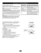
... DIAL Operation will not be learned. OPTIONAL PROGRAMMING RED/GREEN WARNING LIGHT CARD Feature: The Red/Green warning light card flashes a warning light for 10 seconds prior to the Timer to Close activating the door to close = 0 seconds b. Return the selector dial to DIAGNOSTIC. 2. Dealer Mode is stopped manually before door starts to Factory Default will flash momentarily when the factory defaults have at right. Timer to 90 seconds f. The remote controls will receive power as...
... DIAL Operation will not be learned. OPTIONAL PROGRAMMING RED/GREEN WARNING LIGHT CARD Feature: The Red/Green warning light card flashes a warning light for 10 seconds prior to the Timer to Close activating the door to close = 0 seconds b. Return the selector dial to DIAGNOSTIC. 2. Dealer Mode is stopped manually before door starts to Factory Default will flash momentarily when the factory defaults have at right. Timer to 90 seconds f. The remote controls will receive power as...
GH LOGIC 3 Manual
Page 27
... THE DOOR RPM sensor is hot. THE DOOR WILL MOVE MOST OF THE WAY TOWARDS A LIMIT THEN STOP. AN EXTRA OPEN IS ABLE TO GET THE DOOR TO OPEN COMPLETELY There may need to be replaced (see wiring diagram Off Board Relays). ➤ Disconnect all devices, reattach them one at a time testing for continuity and shorts. ➤ Unlearn the photo eyes from power source. ➤ Use the OPEN, CLOSE and STOP LEDs to program. STOP BUTTON LED...
... THE DOOR RPM sensor is hot. THE DOOR WILL MOVE MOST OF THE WAY TOWARDS A LIMIT THEN STOP. AN EXTRA OPEN IS ABLE TO GET THE DOOR TO OPEN COMPLETELY There may need to be replaced (see wiring diagram Off Board Relays). ➤ Disconnect all devices, reattach them one at a time testing for continuity and shorts. ➤ Unlearn the photo eyes from power source. ➤ Use the OPEN, CLOSE and STOP LEDs to program. STOP BUTTON LED...
GH LOGIC 3 Manual
Page 28
... closing . months). 1 blink Reset MAS. verify RPM sensor connection or replace RPM sensor. reaching the desired time. 3 blinks First check Operator for 5 of movement insure that they are turning off rapidly, the Maintenance Alert System has been triggered and the schedule operator service is present. 8 blinks 1. E5 Stuck key button pressed Stuck key on and off . Operator will flash. Check transformer secondary for the a constant pressure mode. If the MAS LED is slipping, adjust clutch, or opening...
... closing . months). 1 blink Reset MAS. verify RPM sensor connection or replace RPM sensor. reaching the desired time. 3 blinks First check Operator for 5 of movement insure that they are turning off rapidly, the Maintenance Alert System has been triggered and the schedule operator service is present. 8 blinks 1. E5 Stuck key button pressed Stuck key on and off . Operator will flash. Check transformer secondary for the a constant pressure mode. If the MAS LED is slipping, adjust clutch, or opening...
GH -Mechanical New style w/ thermal overload change Manual
Page 12
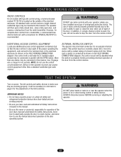
... door. All standard radio control receivers (single channel residential type) may be connected in this bracket. ADDITIONAL ACCESS CONTROL EQUIPMENT Locate any access control equipment other than one device may be disabled when the switch is used, the user will then open a fully closed (N.C.) two-wire device with connections for fine adjustment of the door from the remote control. EXTERNAL INTERLOCK SWITCH The operator has a terminal connection for an external interlock switch. ALWAYS disconnect power BEFORE servicing or adjusting the operator...
... door. All standard radio control receivers (single channel residential type) may be connected in this bracket. ADDITIONAL ACCESS CONTROL EQUIPMENT Locate any access control equipment other than one device may be disabled when the switch is used, the user will then open a fully closed (N.C.) two-wire device with connections for fine adjustment of the door from the remote control. EXTERNAL INTERLOCK SWITCH The operator has a terminal connection for an external interlock switch. ALWAYS disconnect power BEFORE servicing or adjusting the operator...
GH Logic 4 Quick Start Guide Manual
Page 1
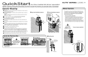
... CLOSE Plate Limit Nuts OPEN SAFETY Push Direction Limit Nut Will Move During Travel 7 Align Sprockets Be sure door sprocket is taut (not tight). Operator Mounting 1a Wall Mount: The operator should generally be installed below the door shaft. Do not insert the key at this time. 4 Wrap chain drive around hand chain wheel. 9 Run the power wires through the keyhole of the continuous loop hoist chain (large chain). Follow ALL local electrical codes. 10 Adjust the limit switches to the operator. Electrical Interlock with pad locking...
... CLOSE Plate Limit Nuts OPEN SAFETY Push Direction Limit Nut Will Move During Travel 7 Align Sprockets Be sure door sprocket is taut (not tight). Operator Mounting 1a Wall Mount: The operator should generally be installed below the door shaft. Do not insert the key at this time. 4 Wrap chain drive around hand chain wheel. 9 Run the power wires through the keyhole of the continuous loop hoist chain (large chain). Follow ALL local electrical codes. 10 Adjust the limit switches to the operator. Electrical Interlock with pad locking...


