
GT- Logic 4 Installation Manual
Page 1
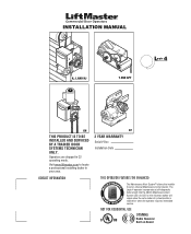
... built into the (MAS) Maintenance Alert System LED. An LED on Board Operators are shipped in your area. Visit www.liftmaster.com to set number of cycles/months is reached or when the operator requires immediate service. NOT FOR RESIDENTIAL USE 315MHz Radio Receiver Built on the ...3-button station will signal when the set an internal Maintenance Cycle Counter. INSTALLATION MANUAL H, J, AND HJ T AND APT L 4 ogic L3 GH...
... built into the (MAS) Maintenance Alert System LED. An LED on Board Operators are shipped in your area. Visit www.liftmaster.com to set number of cycles/months is reached or when the operator requires immediate service. NOT FOR RESIDENTIAL USE 315MHz Radio Receiver Built on the ...3-button station will signal when the set an internal Maintenance Cycle Counter. INSTALLATION MANUAL H, J, AND HJ T AND APT L 4 ogic L3 GH...

GT- Logic 4 Installation Manual
Page 2
... Sensors (Provided 21 Mount the Photoelectric Sensors (Provided 22 Wire the LiftMaster Monitored Entrapment Protection (LMEP) Devices 22 ADJUSTMENT 23-24 Limit Adjustment 23 Clutch Adjustment (Belt Drive Model Operators 24 TESTING 25 MANUAL RELEASE 26-27 Emergency Disconnect System Model GT ...and T 26 Emergency Disconnect System Model APT 26 Emergency Disconnect System Model H, GH, J, and HJ 27 PROGRAMMING 28-35 Introduction ...
... Sensors (Provided 21 Mount the Photoelectric Sensors (Provided 22 Wire the LiftMaster Monitored Entrapment Protection (LMEP) Devices 22 ADJUSTMENT 23-24 Limit Adjustment 23 Clutch Adjustment (Belt Drive Model Operators 24 TESTING 25 MANUAL RELEASE 26-27 Emergency Disconnect System Model GT ...and T 26 Emergency Disconnect System Model APT 26 Emergency Disconnect System Model H, GH, J, and HJ 27 PROGRAMMING 28-35 Introduction ...

GT- Logic 4 Installation Manual
Page 3
... m). • away from electric shock. ADVERTENCIA 12. Disable ALL locks and remove ALL ropes connected to door BEFORE installing operator to cables, spring assemblies and other hardware MUST be installed on wall next to the control station in SEVERE INJURY or DEATH...INFORMATION WARNING Mechanical CWAWAUARTRINONINNINGG Electrical CWAUATRIONINNG WARNING IMPORTANT NOTES: • BEFORE attempting to install, operate or maintain the operator, you do not comply with the door while operating the controls. 10. When you see this manual and follow all safety instructions. WARNING...
... m). • away from electric shock. ADVERTENCIA 12. Disable ALL locks and remove ALL ropes connected to door BEFORE installing operator to cables, spring assemblies and other hardware MUST be installed on wall next to the control station in SEVERE INJURY or DEATH...INFORMATION WARNING Mechanical CWAWAUARTRINONINNINGG Electrical CWAUATRIONINNG WARNING IMPORTANT NOTES: • BEFORE attempting to install, operate or maintain the operator, you do not comply with the door while operating the controls. 10. When you see this manual and follow all safety instructions. WARNING...

GT- Logic 4 Installation Manual
Page 4
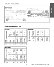
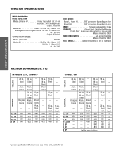
...Entrapment Protection Device: Model CPS-U photoelectric sensors (standard) NOTE: The tracks are shipped separately. See page 29 for emergency manual door operation. OPERATOR SPECIFICATIONS MOTOR TYPE Continuous duty HORSEPOWER: Model APT 1/2 HP Model GT 1/2, 3/4, 1 and 1-1/2 HP Model T 1/3, 1/2, 3/4... pressure to CLOSE, plus wiring for 3/4 HP and higher (all components were provided. Carton inventory/Operator specifications - ENTRAPMENT PROTECTION: LiftMaster Monitored Entrapment Protection (LMEP) Photoelectric Sensors (CPS-U Through beam used to 24 feet. Safety Edge ...
...Entrapment Protection Device: Model CPS-U photoelectric sensors (standard) NOTE: The tracks are shipped separately. See page 29 for emergency manual door operation. OPERATOR SPECIFICATIONS MOTOR TYPE Continuous duty HORSEPOWER: Model APT 1/2 HP Model GT 1/2, 3/4, 1 and 1-1/2 HP Model T 1/3, 1/2, 3/4... pressure to CLOSE, plus wiring for 3/4 HP and higher (all components were provided. Carton inventory/Operator specifications - ENTRAPMENT PROTECTION: LiftMaster Monitored Entrapment Protection (LMEP) Photoelectric Sensors (CPS-U Through beam used to 24 feet. Safety Edge ...
GT- Logic 4 Installation Manual
Page 5
... 3/4 HP 560 500 1 HP 625 575 1-1/2 HP --- 625 20 ga. Steel Wood Doors 24 ga. Steel Insul. 200 250 300 380 5 Operator specifications/Maximum door area - Doors --- --- 1/3 HP 310 285 1/2 HP 400 350 3/4 HP 560 500 1 HP 640 625 20 ga. Trolley ...TROLLEY OPERATOR SPECIFICATIONS MECHANICAL DRIVE REDUCTION: Model APT and T Primary: Heavy duty (5L) V-Belt Secondary: #41 chain/sprocket; Steel --- 20 ga. Output: #48 ...
... 3/4 HP 560 500 1 HP 625 575 1-1/2 HP --- 625 20 ga. Steel Wood Doors 24 ga. Steel Insul. 200 250 300 380 5 Operator specifications/Maximum door area - Doors --- --- 1/3 HP 310 285 1/2 HP 400 350 3/4 HP 560 500 1 HP 640 625 20 ga. Trolley ...TROLLEY OPERATOR SPECIFICATIONS MECHANICAL DRIVE REDUCTION: Model APT and T Primary: Heavy duty (5L) V-Belt Secondary: #41 chain/sprocket; Steel --- 20 ga. Output: #48 ...
GT- Logic 4 Installation Manual
Page 7
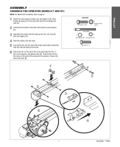
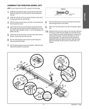
... the trolley with the take up bolt (C), hex nuts (E), and lock washer (D). 4 Slide the trolley onto the track. 5 Insert bolts (A) into the "L" slot in the operator and tighten nuts (B). Insert bolts (A) into the holes on the end of the track assembly into the end of the track and loosely thread the... bolt (A) and flange hex nuts (B). 2 Install the front idler to page 9. 1 Install the track spacers evenly over the length of the track and the operator.
... the trolley with the take up bolt (C), hex nuts (E), and lock washer (D). 4 Slide the trolley onto the track. 5 Insert bolts (A) into the "L" slot in the operator and tighten nuts (B). Insert bolts (A) into the holes on the end of the track assembly into the end of the track and loosely thread the... bolt (A) and flange hex nuts (B). 2 Install the front idler to page 9. 1 Install the track spacers evenly over the length of the track and the operator.
GT- Logic 4 Installation Manual
Page 8
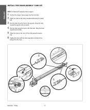
... master link. 3 Run the chain along the track to the front of the track. 2 1 2˝ MODEL T 3 MODEL GT 4 5 6 3˝ Assembly - Wrap the chain around the operator drive sprocket. 4 Run the chain along the track to the...
... master link. 3 Run the chain along the track to the front of the track. 2 1 2˝ MODEL T 3 MODEL GT 4 5 6 3˝ Assembly - Wrap the chain around the operator drive sprocket. 4 Run the chain along the track to the...
GT- Logic 4 Installation Manual
Page 9
... to the free end of the drive link using a master link. 10 Attach the other end of the track). Trolley Wrap the chain around the operator drive sprocket. 2 6 1 3 8 9 10 3˝ 9 4 7 5 Assembly - Wrap the chain around the front idler. 9 Attach one end of the chain to the drive link using a master ...sag about 3 inches at the mid point of the chain to the next page. TROLLEY ASSEMBLE THE OPERATOR (MODEL APT) NOTE: If your model is no binding. 7 Run the chain along the track to the operator. Pull the release clip on the end of the track with nuts (B). 6 Run the chain ...
... to the free end of the drive link using a master link. 10 Attach the other end of the track). Trolley Wrap the chain around the operator drive sprocket. 2 6 1 3 8 9 10 3˝ 9 4 7 5 Assembly - Wrap the chain around the front idler. 9 Attach one end of the chain to the drive link using a master ...sag about 3 inches at the mid point of the chain to the next page. TROLLEY ASSEMBLE THE OPERATOR (MODEL APT) NOTE: If your model is no binding. 7 Run the chain along the track to the operator. Pull the release clip on the end of the track with nuts (B). 6 Run the chain ...
GT- Logic 4 Installation Manual
Page 10
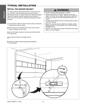
Typically, the operator may be used if mounting header bracket or 2x4 into masonry. • NEVER try to loosen, move or adjust door, springs, cables, pulleys, brackets, or ... up to structural support on header wall or ceiling, otherwise door might NOT reverse when required. TROLLEY TYPICAL INSTALLATION INSTALL THE HEADER BRACKET The trolley operator is out of door stile / top section support. Trolley 5 ADVERTENCIA PRECAUCIÓN 3 4" 4 10
Typically, the operator may be used if mounting header bracket or 2x4 into masonry. • NEVER try to loosen, move or adjust door, springs, cables, pulleys, brackets, or ... up to structural support on header wall or ceiling, otherwise door might NOT reverse when required. TROLLEY TYPICAL INSTALLATION INSTALL THE HEADER BRACKET The trolley operator is out of door stile / top section support. Trolley 5 ADVERTENCIA PRECAUCIÓN 3 4" 4 10
GT- Logic 4 Installation Manual
Page 11
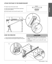
Trolley HARDWARE Header Pivot Pin (1) Cotter pins (2) 1 2 3 WARNING HANG THE OPERATOR 1 Secure the operator using the appropriate fasteners and locking hardware that will support the weight of the building. • Concrete anchors MUST be used if ...TO THE HEADER BRACKET 1 Align the track with the fasteners. 3 Swing the operator up and ensure the operator is level. CAUTION To avoid possible SERIOUS INJURY from a falling operator: • Fasten the operator SECURELY to structural supports of the operator. Secure with the header bracket. 2 Insert the pin through the track and ...
Trolley HARDWARE Header Pivot Pin (1) Cotter pins (2) 1 2 3 WARNING HANG THE OPERATOR 1 Secure the operator using the appropriate fasteners and locking hardware that will support the weight of the building. • Concrete anchors MUST be used if ...TO THE HEADER BRACKET 1 Align the track with the fasteners. 3 Swing the operator up and ensure the operator is level. CAUTION To avoid possible SERIOUS INJURY from a falling operator: • Fasten the operator SECURELY to structural supports of the operator. Secure with the header bracket. 2 Insert the pin through the track and ...
GT- Logic 4 Installation Manual
Page 12
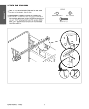
... Nut 3/8"-16 (2) B Nylok Nut 3/8"-16 (1) Bolt 3/8"-16 x 1" (3) NOTICE 1 A B 2 Typical installation - NOTE: When properly installed and adjusted the door arm should be leaning back toward the operator slightly. Refer to the door using appropriate hardware (not included). Make sure the open side of the notch on the door arm faces the door...
... Nut 3/8"-16 (2) B Nylok Nut 3/8"-16 (1) Bolt 3/8"-16 x 1" (3) NOTICE 1 A B 2 Typical installation - NOTE: When properly installed and adjusted the door arm should be leaning back toward the operator slightly. Refer to the door using appropriate hardware (not included). Make sure the open side of the notch on the door arm faces the door...

GT- Logic 4 Installation Manual
Page 13
... non-contact safety protection. SAFETY DISCONNECT: Model J . . . . .Floor level disconnect for manual door operation Model H and GH Floor level chain hoist with electrical interlock for manual door operation Model HJ Includes both floor level disconnect systems stated above ENTRAPMENT PROTECTION: LiftMaster Monitored Entrapment Protection (LMEP) Photoelectric Sensors (CPS-U Through beam used to 24 feet...
... non-contact safety protection. SAFETY DISCONNECT: Model J . . . . .Floor level disconnect for manual door operation Model H and GH Floor level chain hoist with electrical interlock for manual door operation Model HJ Includes both floor level disconnect systems stated above ENTRAPMENT PROTECTION: LiftMaster Monitored Entrapment Protection (LMEP) Photoelectric Sensors (CPS-U Through beam used to 24 feet...
GT- Logic 4 Installation Manual
Page 14
... --- --- --- 250 340 430 540 640 875 Call for 3 HP DOOR SPEED: Model J, H and HJ 8-9" per second depending on door Model GH 8-9" per second depending on door BRAKE Solenoid actuated disc brake BEARINGS Output Shaft: Shielded Ball Bearing Clutch Shaft: IronCopper sintered and oil impregnated Models H and.... Steel Insul. 225 275 325 425 560 840 --- --- --- --- 16 ga. FT.) MODELS J, H, AND HJ 24 ga. 22 ga. Steel Alum. OPERATOR SPECIFICATIONS MECHANICAL DRIVE REDUCTION: Model J, H, and HJ Primary: Heavy duty (5L) V-Belt Secondary: #48 chain/sprocket; Steel Insul. 175 225 300 375 460 620...
... --- --- --- 250 340 430 540 640 875 Call for 3 HP DOOR SPEED: Model J, H and HJ 8-9" per second depending on door Model GH 8-9" per second depending on door BRAKE Solenoid actuated disc brake BEARINGS Output Shaft: Shielded Ball Bearing Clutch Shaft: IronCopper sintered and oil impregnated Models H and.... Steel Insul. 225 275 325 425 560 840 --- --- --- --- 16 ga. FT.) MODELS J, H, AND HJ 24 ga. 22 ga. Steel Alum. OPERATOR SPECIFICATIONS MECHANICAL DRIVE REDUCTION: Model J, H, and HJ Primary: Heavy duty (5L) V-Belt Secondary: #48 chain/sprocket; Steel Insul. 175 225 300 375 460 620...
GT- Logic 4 Installation Manual
Page 15
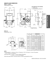
... with 1" x 1/4" key for 1/2 thru 1 HP operators, 1-3/16" x 5/16" key for 1-1/2 and 2 HP operators, 1-1/4" x 1/4" key for 3 HP operators. 2) Mounting centers: X = 4-3/4"; Y = 9-1/16" for 1/2 thru 2 HP operators. Y = 5-1/2" for 3 HP operators. 3) Hand chain wheel extends 1-5/8" beyond operator in vertical mounting position as shown. 15 Weights and dimensions... 3-15/16 NOTES: 1) Output shaft with Models H and HJ ONLY 4.56" (11.58 cm) HOIST AND JACKSHAFT MODEL GH Hanging Weight: 140 lbs. WEIGHTS AND DIMENSIONS MODELS J, H AND HJ Hanging Weight: 80-110 lbs. 14.5" (36.83 cm...
... with 1" x 1/4" key for 1/2 thru 1 HP operators, 1-3/16" x 5/16" key for 1-1/2 and 2 HP operators, 1-1/4" x 1/4" key for 3 HP operators. 2) Mounting centers: X = 4-3/4"; Y = 9-1/16" for 1/2 thru 2 HP operators. Y = 5-1/2" for 3 HP operators. 3) Hand chain wheel extends 1-5/8" beyond operator in vertical mounting position as shown. 15 Weights and dimensions... 3-15/16 NOTES: 1) Output shaft with Models H and HJ ONLY 4.56" (11.58 cm) HOIST AND JACKSHAFT MODEL GH Hanging Weight: 140 lbs. WEIGHTS AND DIMENSIONS MODELS J, H AND HJ Hanging Weight: 80-110 lbs. 14.5" (36.83 cm...

GT- Logic 4 Installation Manual
Page 16
...Provide a level base. Permit the operator to prevent play between PRECAUCIÓN the door shaft and operator drive shaft is imperative that the wall or mounting surface provide adequate support for the operator. On models J, H, HJ and GH operators the drive sprocket can cause SERIOUS ...PERSONAL INJURY. • Disable ALL locks and remove ALL ropes connected to door AVERTISSEMENT BEFORE installing and operating door operator to avoid entanglement. • Fasten the operator SECURELY to ...
...Provide a level base. Permit the operator to prevent play between PRECAUCIÓN the door shaft and operator drive shaft is imperative that the wall or mounting surface provide adequate support for the operator. On models J, H, HJ and GH operators the drive sprocket can cause SERIOUS ...PERSONAL INJURY. • Disable ALL locks and remove ALL ropes connected to door AVERTISSEMENT BEFORE installing and operating door operator to avoid entanglement. • Fasten the operator SECURELY to ...

GT- Logic 4 Installation Manual
Page 17
... the master link. 4 Align the door and the drive sprockets. MOUNTING 1 Place the door sprocket on the door shaft. 2 Place the operator drive sprocket on the appropriate side of the operator for your installation type. 3 Wrap the drive chain around the door sprocket and the drive sprocket then secure with the set...
... the master link. 4 Align the door and the drive sprockets. MOUNTING 1 Place the door sprocket on the door shaft. 2 Place the operator drive sprocket on the appropriate side of the operator for your installation type. 3 Wrap the drive chain around the door sprocket and the drive sprocket then secure with the set...
GT- Logic 4 Installation Manual
Page 18
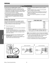
... be visible and clearly labeled. • ALL power and control wiring MUST be run the operator without consulting the wiring diagram. • ALL power wiring should be connected to the operator or in the wrong direction. Locate the MOTOR DIRECTION jumper on a separate fused line of ... • DO NOT install ANY wiring or attempt to rotate in the area near the operator MUST NOT be performed until disconnecting the electrical power and locking-out the power. Operator MUST be properly grounded and connected in accordance with national and local electrical codes. Relocate the...
... be visible and clearly labeled. • ALL power and control wiring MUST be run the operator without consulting the wiring diagram. • ALL power wiring should be connected to the operator or in the wrong direction. Locate the MOTOR DIRECTION jumper on a separate fused line of ... • DO NOT install ANY wiring or attempt to rotate in the area near the operator MUST NOT be performed until disconnecting the electrical power and locking-out the power. Operator MUST be properly grounded and connected in accordance with national and local electrical codes. Relocate the...
GT- Logic 4 Installation Manual
Page 19
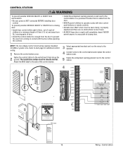
...the control station to prevent the user from coming in Sight at . Door May Move at any Time Without Prior Warning Do Not Let Children Operate the Door or Play in the Door Area Keep Door in contact with door control push buttons or remote controls. • Activate door ONLY when... warning placard next to door travel. • ALWAYS keep door in a prominent location that is visible from the door. • NEVER permit children to operate or play with the door while operating the controls. Refer to back page for additional control Select appropriate knockout and run the wires to the...
...the control station to prevent the user from coming in Sight at . Door May Move at any Time Without Prior Warning Do Not Let Children Operate the Door or Play in the Door Area Keep Door in contact with door control push buttons or remote controls. • Activate door ONLY when... warning placard next to door travel. • ALWAYS keep door in a prominent location that is visible from the door. • NEVER permit children to operate or play with the door while operating the controls. Refer to back page for additional control Select appropriate knockout and run the wires to the...
GT- Logic 4 Installation Manual
Page 20
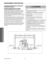
... path of its invisible light beam. The LEDs on both the leading and trailing edge. • If an edge sensor is required for use with LiftMaster Commercial Door Operators ONLY. Use with the photoelectric sensors model CPS-U, additional entrapment devices are for most wiring types (refer to the door...
... path of its invisible light beam. The LEDs on both the leading and trailing edge. • If an edge sensor is required for use with LiftMaster Commercial Door Operators ONLY. Use with the photoelectric sensors model CPS-U, additional entrapment devices are for most wiring types (refer to the door...
GT- Logic 4 Installation Manual
Page 22
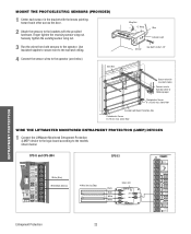
...the bracket with the lenses pointing toward each other across the door. 2 Attach the sensors to the brackets with insulated staples Connect wire to Operator (refer to following page) Photoelectric Sensor 6" (15 cm) max. Bell Wire Wing Nut "C" Wrap Wire Indicator Light Sensor Hex Bolt ... PROTECTION Secure wire with the provided hardware. Finger tighten the receiving sensor wing nut. above floor WIRE THE LIFTMASTER MONITORED ENTRAPMENT PROTECTION (LMEP) DEVICES 1 Connect the LiftMaster Monitored Entrapment Protection (LMEP) device to the logic board according to the...
...the bracket with the lenses pointing toward each other across the door. 2 Attach the sensors to the brackets with insulated staples Connect wire to Operator (refer to following page) Photoelectric Sensor 6" (15 cm) max. Bell Wire Wing Nut "C" Wrap Wire Indicator Light Sensor Hex Bolt ... PROTECTION Secure wire with the provided hardware. Finger tighten the receiving sensor wing nut. above floor WIRE THE LIFTMASTER MONITORED ENTRAPMENT PROTECTION (LMEP) DEVICES 1 Connect the LiftMaster Monitored Entrapment Protection (LMEP) device to the logic board according to the...


