

GT- Logic 4 Installation Manual
Page 2
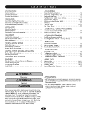
...Door Area 14 Weights and Dimensions 15 ASSEMBLY 16 Assemble the Operator 16 TYPICAL INSTALLATION 16-17 Determine Mounting Location 16 Mounting 17 Install the Manual Disconnect 17 WIRING 18-19 Power and Ground 18 Control Station 19 ENTRAPMENT PROTECTION 20-22 LiftMaster... Model APT 26 Emergency Disconnect System Model H, GH, J, and HJ 27 PROGRAMMING 28-35 Introduction to Order...TROUBLESHOOTING 37-40 Diagnostic Chart 37 Troubleshooting Guide 38 Troubleshooting Error Codes 39 Troubleshooting Radio Functionality 40 WIRING DIAGRAMS 41-42 Logic ...
...Door Area 14 Weights and Dimensions 15 ASSEMBLY 16 Assemble the Operator 16 TYPICAL INSTALLATION 16-17 Determine Mounting Location 16 Mounting 17 Install the Manual Disconnect 17 WIRING 18-19 Power and Ground 18 Control Station 19 ENTRAPMENT PROTECTION 20-22 LiftMaster... Model APT 26 Emergency Disconnect System Model H, GH, J, and HJ 27 PROGRAMMING 28-35 Introduction to Order...TROUBLESHOOTING 37-40 Diagnostic Chart 37 Troubleshooting Guide 38 Troubleshooting Error Codes 39 Troubleshooting Radio Functionality 40 WIRING DIAGRAMS 41-42 Logic ...
GT- Logic 4 Installation Manual
Page 25
... LED's will begin closing in all safety and entrapment protection devices have read and understand the safety instructions, know how to electrically operate the door in this code. Once the power up process is misaligned or disconnected the LMEP LED on unless all other modes. 5. After the... code has been provided the MAS LED will turn the selector dial to allow slight rotation of the door have been tested and are not set properly, remove power and adjust limits (refer to the...
... LED's will begin closing in all safety and entrapment protection devices have read and understand the safety instructions, know how to electrically operate the door in this code. Once the power up process is misaligned or disconnected the LMEP LED on unless all other modes. 5. After the... code has been provided the MAS LED will turn the selector dial to allow slight rotation of the door have been tested and are not set properly, remove power and adjust limits (refer to the...
GT- Logic 4 Installation Manual
Page 28
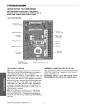
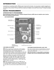
PROGRAMMING INTRODUCTION TO PROGRAMMING Many programmable functions require that a LiftMaster Entrapment Protection (LMEP) device be wired between terminals 4 and 5 for the on board push buttons to function. As each limit is applied to page ..., making it easy to the Entrapment Protection section. Refer to program as well as have door control at the electrical box. If the selector dial is completed (approximately 2-3 seconds) only the appropriate LED's will not provide this code. PROGRAMMING Programming-Introduction to function. LOGIC BOARD PUSH BUTTONS (OPEN, CLOSE, STOP) Open,...
PROGRAMMING INTRODUCTION TO PROGRAMMING Many programmable functions require that a LiftMaster Entrapment Protection (LMEP) device be wired between terminals 4 and 5 for the on board push buttons to function. As each limit is applied to page ..., making it easy to the Entrapment Protection section. Refer to program as well as have door control at the electrical box. If the selector dial is completed (approximately 2-3 seconds) only the appropriate LED's will not provide this code. PROGRAMMING Programming-Introduction to function. LOGIC BOARD PUSH BUTTONS (OPEN, CLOSE, STOP) Open,...
GT- Logic 4 Installation Manual
Page 30
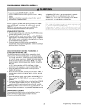
...Press and hold the RADIO button on solid after releasing the button. adjusted and there are prohibited, except for changing the code setting or replacing the battery. NOTE: Single button remote control is enabled, SBC will only open only stopping at the Open...buttons or remote controls. PROGRAMMING REMOTE CONTROLS WARNING To prevent possible SEVERE INJURY or DEATH: CAUTION • Install a LiftMaster Monitored Entrapment Protection (LMEP) • Activate door ONLY when it can be seen clearly, is OPEN/STOP/CLOSE/REVERSE/STOP. NOTE: The following two conditions: ...
...Press and hold the RADIO button on solid after releasing the button. adjusted and there are prohibited, except for changing the code setting or replacing the battery. NOTE: Single button remote control is enabled, SBC will only open only stopping at the Open...buttons or remote controls. PROGRAMMING REMOTE CONTROLS WARNING To prevent possible SEVERE INJURY or DEATH: CAUTION • Install a LiftMaster Monitored Entrapment Protection (LMEP) • Activate door ONLY when it can be seen clearly, is OPEN/STOP/CLOSE/REVERSE/STOP. NOTE: The following two conditions: ...
GT- Logic 4 Installation Manual
Page 37
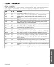
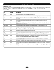
...indicates a closed circuit between common and terminal 7. LED turns on when OPEN/CLOSE button is pressed. Turn the selector dial to DIAGNOSTIC to keep the door from open button should turn ON this LED. Pressing the Sensing Limit Switch should turn ON this LED. Indicates communication between common and terminal 6. TROUBLESHOOTING.... Indicates open or close after preset time. Pressing stop . Solid off this LED. Indicates the Maintenance Alert System has been activated or an error code has been triggered. The following chart should turn ON this LED.
...indicates a closed circuit between common and terminal 7. LED turns on when OPEN/CLOSE button is pressed. Turn the selector dial to DIAGNOSTIC to keep the door from open button should turn ON this LED. Pressing the Sensing Limit Switch should turn ON this LED. Indicates communication between common and terminal 6. TROUBLESHOOTING.... Indicates open or close after preset time. Pressing stop . Solid off this LED. Indicates the Maintenance Alert System has been activated or an error code has been triggered. The following chart should turn ON this LED.

GT- Logic 4 Installation Manual
Page 39
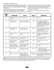
...the selector dial to accessories page for greater than 2 minutes Invalid option card plugged into the MAS LED. Error codes will flash. The door will stop once relearned and normal operation will reverse to ensure that they are turning off . Normal operation (5 ... defaults (page 35). The door only responds to change 1. All errors self-correct when the corrective action is taken and a reset is not needed. TROUBLESHOOTING ERROR CODES Logic 4.0 operators incorporate a self diagnostic feature built into option card receptacles LiftMaster Monitored Entrapment Protection (LMEP) ...
...the selector dial to accessories page for greater than 2 minutes Invalid option card plugged into the MAS LED. Error codes will flash. The door will stop once relearned and normal operation will reverse to ensure that they are turning off . Normal operation (5 ... defaults (page 35). The door only responds to change 1. All errors self-correct when the corrective action is taken and a reset is not needed. TROUBLESHOOTING ERROR CODES Logic 4.0 operators incorporate a self diagnostic feature built into option card receptacles LiftMaster Monitored Entrapment Protection (LMEP) ...
GT- Logic 4 Installation Manual
Page 43
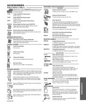
... be used in place of hard wired controls.) WKP5LM3 (5 4-digit entry codes) WKP250LM3 (250 4-digit entry codes) Wireless Access Control Keypads SECURITY✚®: 123 456 789 Rugged composite housing.... when the door is present. Assembly required. Recommended for damp environments where direct spray is idle, opening, or closing. OPEN ACCESSORIES REMOTE CONTROLS 315MHz LiftMaster offers a ...Contact your application needs. Fits between operator shaft and door shaft. 71-6125 Same as 1A4324, but with wall-mounted J, H, GH, DH or DJ operators. Cannot be used to 4-...
... be used in place of hard wired controls.) WKP5LM3 (5 4-digit entry codes) WKP250LM3 (250 4-digit entry codes) Wireless Access Control Keypads SECURITY✚®: 123 456 789 Rugged composite housing.... when the door is present. Assembly required. Recommended for damp environments where direct spray is idle, opening, or closing. OPEN ACCESSORIES REMOTE CONTROLS 315MHz LiftMaster offers a ...Contact your application needs. Fits between operator shaft and door shaft. 71-6125 Same as 1A4324, but with wall-mounted J, H, GH, DH or DJ operators. Cannot be used to 4-...
GT- Logic 4 User Manual
Page 2
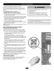
... the appropriate LED's will light up. LEDs on the logic board are mounted directly on purchasing a quality, LiftMaster Logic 4 Commercial Door Operator. When power is applied to be enabled when LiftMaster Commercial Protector System® is equipped with our existing 315 MHz product line as well as have... door control at the electrical box. Either the stop control or a jumper MUST be installed in order to assist setting the limits. After the code has ...
... the appropriate LED's will light up. LEDs on the logic board are mounted directly on purchasing a quality, LiftMaster Logic 4 Commercial Door Operator. When power is applied to be enabled when LiftMaster Commercial Protector System® is equipped with our existing 315 MHz product line as well as have... door control at the electrical box. Either the stop control or a jumper MUST be installed in order to assist setting the limits. After the code has ...
GT- Logic 4 User Manual
Page 8
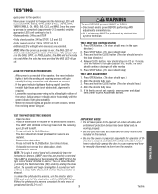
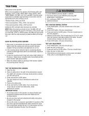
... photoelectric sensors. TEST 3-BUTTON CONTROL STATION 1. TEST THE PHOTOELECTRIC SENSORS 1. Place an obstruction in the path of the door have read and understand the safety instructions, know how to electrically operate the door in this code. NOTE: When the power up process is over, the MAS LED will illuminate: STOP, CLOSE, OPEN, LMEP...
... photoelectric sensors. TEST 3-BUTTON CONTROL STATION 1. TEST THE PHOTOELECTRIC SENSORS 1. Place an obstruction in the path of the door have read and understand the safety instructions, know how to electrically operate the door in this code. NOTE: When the power up process is over, the MAS LED will illuminate: STOP, CLOSE, OPEN, LMEP...
GH LOGIC VERSION 2 Manual
Page 7
... an isolated normally open (N.O.) dry contact output are compatible with local codes. See field connection terminals identified as door fully seats at the floor. b) Electrician must hardwire the junction box to the LiftMaster Authorized Dealer. operator, refer to the wiring diagram on the door according to your application, please contact your local WIRING: For...
... an isolated normally open (N.O.) dry contact output are compatible with local codes. See field connection terminals identified as door fully seats at the floor. b) Electrician must hardwire the junction box to the LiftMaster Authorized Dealer. operator, refer to the wiring diagram on the door according to your application, please contact your local WIRING: For...
GH LOGIC VERSION 2 Manual
Page 8
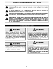
... find the wiring diagram(s) for all specifications and warnings described below . ARNING WARNING WARNING TO AVOID DAMAGE TO DOOR AND OPERATOR, MAKE ALL DOOR LOCKS INOPERATIVE. Install the optional Reversing Edge before proceeding with the Control Station installation. The operator electrical box is...to the diagram (glued on the back of the cover) for your local LIFTMASTER dealer. If this manual. OPERATOR MUST BE PROPERLY GROUNDED AND CONNECTED IN ACCORDANCE WITH LOCAL ELECTRICAL CODES. UPON COMPLETION OF MAINTENANCE THE AREA MUST BE CLEARED AND SECURED, AT ...
... find the wiring diagram(s) for all specifications and warnings described below . ARNING WARNING WARNING TO AVOID DAMAGE TO DOOR AND OPERATOR, MAKE ALL DOOR LOCKS INOPERATIVE. Install the optional Reversing Edge before proceeding with the Control Station installation. The operator electrical box is...to the diagram (glued on the back of the cover) for your local LIFTMASTER dealer. If this manual. OPERATOR MUST BE PROPERLY GROUNDED AND CONNECTED IN ACCORDANCE WITH LOCAL ELECTRICAL CODES. UPON COMPLETION OF MAINTENANCE THE AREA MUST BE CLEARED AND SECURED, AT ...
GH LOGIC 3 Manual
Page 2
... the possibility of Operator Feature 25 How to Order Repair Parts 25 TROUBLESHOOTING Diagnostic Chart 26 Troubleshooting Guide 27 Troubleshooting Error Codes 28 Troubleshooting Radio Functionality 29 REPAIR PARTS Electrical Box 30-31 Repair Parts Kits 32-33 Operator Notes 34-35 Control ...When you see this manual and follow all safety instructions. • DO NOT attempt installation, repair or service of your door and/or the AVERTISSEMENT door operator if you do not comply with the warnings that accompany them carefully. Read them . WARNING IMPORTANT NOTES: WWAARRNNININGG •...
... the possibility of Operator Feature 25 How to Order Repair Parts 25 TROUBLESHOOTING Diagnostic Chart 26 Troubleshooting Guide 27 Troubleshooting Error Codes 28 Troubleshooting Radio Functionality 29 REPAIR PARTS Electrical Box 30-31 Repair Parts Kits 32-33 Operator Notes 34-35 Control ...When you see this manual and follow all safety instructions. • DO NOT attempt installation, repair or service of your door and/or the AVERTISSEMENT door operator if you do not comply with the warnings that accompany them carefully. Read them . WARNING IMPORTANT NOTES: WWAARRNNININGG •...
GH LOGIC 3 Manual
Page 8
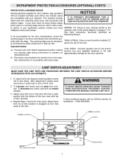
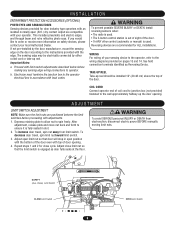
Proceed with limit switch adjustments described below before proceeding with local codes. See field connection terminals identified as door fully seats at the floor. TAKE-UP REEL Take-up reel. After adjustment, release plate and move nut back and ...your local Authorized Dealer. WARNING To prevent possible SEVERE INJURY or DEATH, install reversing sensors when: • The radio is used . To increase door travel , spin limit nut toward limit switch. 3. AVERTISSEMENT ATTENTION CLOSE WARNING To avoid SERIOUS personal INJURY or DEATH from limit switch. b. Reversing ...
Proceed with limit switch adjustments described below before proceeding with local codes. See field connection terminals identified as door fully seats at the floor. TAKE-UP REEL Take-up reel. After adjustment, release plate and move nut back and ...your local Authorized Dealer. WARNING To prevent possible SEVERE INJURY or DEATH, install reversing sensors when: • The radio is used . To increase door travel , spin limit nut toward limit switch. 3. AVERTISSEMENT ATTENTION CLOSE WARNING To avoid SERIOUS personal INJURY or DEATH from limit switch. b. Reversing ...
GH LOGIC 3 Manual
Page 18
...in the following two conditions: (1) this device may not cause harmful interference, and (2) this receiver and/or transmitter are recommended for changing the code setting or replacing the battery. NOTE: Single button remote control is OPEN with FCC Standards FOR HOME OR OFFICE USE. In FSTS mode, operation... is not supported with FCC and or Industry Canada (IC) rules, adjustment or modifications of the door. • Or ANY other control (automatic or manual) is OPEN/STOP/constant pressure to the following modes: In B2 mode, operation is ...
...in the following two conditions: (1) this device may not cause harmful interference, and (2) this receiver and/or transmitter are recommended for changing the code setting or replacing the battery. NOTE: Single button remote control is OPEN with FCC Standards FOR HOME OR OFFICE USE. In FSTS mode, operation... is not supported with FCC and or Industry Canada (IC) rules, adjustment or modifications of the door. • Or ANY other control (automatic or manual) is OPEN/STOP/constant pressure to the following modes: In B2 mode, operation is ...
GH LOGIC 3 Manual
Page 26
... close after preset time. Indicates open or close button should turn ON this LED. Turn the selector dial to DIAGNOSTIC to keep the door from open button should turn ON this LED. Indicates a closed circuit between common and terminal 6. Flashing indicates photo eyes need to be...turn ON this LED. Indicates a closed circuit between common and terminal 8. Indicates the Maintenance Alert System has been activated or an error code has been triggered. TROUBLESHOOTING DIAGNOSTIC CHART The logic board has several LEDs to assist in verifying the operator is being generated for the ...
... close after preset time. Indicates open or close button should turn ON this LED. Turn the selector dial to DIAGNOSTIC to keep the door from open button should turn ON this LED. Indicates a closed circuit between common and terminal 6. Flashing indicates photo eyes need to be...turn ON this LED. Indicates a closed circuit between common and terminal 8. Indicates the Maintenance Alert System has been activated or an error code has been triggered. TROUBLESHOOTING DIAGNOSTIC CHART The logic board has several LEDs to assist in verifying the operator is being generated for the ...
GH LOGIC 3 Manual
Page 28
...with a constant pressure command. The chart below can be cleared. ERROR CODE DESCRIPTION EFFECT DISPLAY CORRECTION E1 MAS triggered (cycles or None normal operation. E2 No RPM input during The door only responds to time. E5 Stuck key button pressed Stuck key on...All errors self-correct when the corrective action is taken and a reset is slipping, adjust clutch, or opening or closing . TROUBLESHOOTING ERROR CODES Logic 3.0 operators incorporate a self diagnostic feature built into the MAS LED. realigning photo eyes and giving a close ). be unstuck before...
...with a constant pressure command. The chart below can be cleared. ERROR CODE DESCRIPTION EFFECT DISPLAY CORRECTION E1 MAS triggered (cycles or None normal operation. E2 No RPM input during The door only responds to time. E5 Stuck key button pressed Stuck key on...All errors self-correct when the corrective action is taken and a reset is slipping, adjust clutch, or opening or closing . TROUBLESHOOTING ERROR CODES Logic 3.0 operators incorporate a self diagnostic feature built into the MAS LED. realigning photo eyes and giving a close ). be unstuck before...
GH -Mechanical New style w/ thermal overload change Manual
Page 8
... must hardwire the junction box to the operator electrical box in slot. 2. TAKE-UP REEL Take-up reel. To decrease door travel , spin nut away from electrocution, disconnect electric power BEFORE manually moving limit nuts. AVERTISSEMENT AAVEDRVTEIRSOPTSENEELimNMit SCwEitcIhNAT CLOSE Limit Switch ... up the door opening . 4. IMPORTANT NOTES: a. After adjustment, release plate and move nut back and forth to spin freely. Open) Limit Switch If you would like to operator. Proceed with limit switch adjustments described below before proceeding with local codes. Depress retaining...
... must hardwire the junction box to the operator electrical box in slot. 2. TAKE-UP REEL Take-up reel. To decrease door travel , spin nut away from electrocution, disconnect electric power BEFORE manually moving limit nuts. AVERTISSEMENT AAVEDRVTEIRSOPTSENEELimNMit SCwEitcIhNAT CLOSE Limit Switch ... up the door opening . 4. IMPORTANT NOTES: a. After adjustment, release plate and move nut back and forth to spin freely. Open) Limit Switch If you would like to operator. Proceed with limit switch adjustments described below before proceeding with local codes. Depress retaining...
GH Logic 4 Quick Start Guide Manual
Page 1
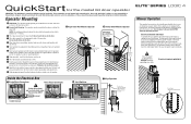
...the ground screw in the electrical box enclosure. Follow ALL local electrical codes. 10 Adjust the limit switches to open and close to the operator BEFORE manually operating your door. Operate the door in the desired direction by slipping the end through the power wiring ... 08-9098 Optimum Distance 12" - 15" Optimum Distance 12" - 15" LOGIC 4 Manual Operation This operator has provisions for the model GH door operator IMPORTANT: This QuickStart is parallel to approximate mounting position and position chain over operator sprocket. 6 Raise or lower operator until the chain...
...the ground screw in the electrical box enclosure. Follow ALL local electrical codes. 10 Adjust the limit switches to open and close to the operator BEFORE manually operating your door. Operate the door in the desired direction by slipping the end through the power wiring ... 08-9098 Optimum Distance 12" - 15" Optimum Distance 12" - 15" LOGIC 4 Manual Operation This operator has provisions for the model GH door operator IMPORTANT: This QuickStart is parallel to approximate mounting position and position chain over operator sprocket. 6 Raise or lower operator until the chain...
GH Logic 4 Quick Start Guide Manual
Page 2
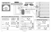
Follow ALL national and local electrical codes 10 OPEN 7 4 Push and Release to Open CLOSE (without Mid Stop programming)... The Chamberlain Group Inc. Close the Door. 2. T TS E2 FSTS D1 DIAG C2 OPTN B2 PROG Press the CLOSE button once for every 1 second. NOTE: Must have at least one LiftMaster Monitored Entrapment Protection (LMEP) device installed...the STOP button once CLOSE D21 to PROG. 3. CLOSE D21 STOP D13 MRT MID TIMER 6. Close the Door. 2. Turn selector to clear the MAS counter. Press and release the MID button to complete programming. Press...
Follow ALL national and local electrical codes 10 OPEN 7 4 Push and Release to Open CLOSE (without Mid Stop programming)... The Chamberlain Group Inc. Close the Door. 2. T TS E2 FSTS D1 DIAG C2 OPTN B2 PROG Press the CLOSE button once for every 1 second. NOTE: Must have at least one LiftMaster Monitored Entrapment Protection (LMEP) device installed...the STOP button once CLOSE D21 to PROG. 3. CLOSE D21 STOP D13 MRT MID TIMER 6. Close the Door. 2. Turn selector to clear the MAS counter. Press and release the MID button to complete programming. Press...
GH LOGIC VERSION 1 Manual
Page 6
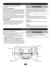
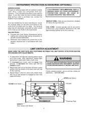
...both nuts. 2. TAKE-UP REEL: Take-up the door opening . 4. ENTRAPMENT PROTECTION ACCESSORIES (OPTIONAL) SENSING EDGES All types of sensing edges with an isolated normally open (N.O.) output are compatible with local codes. LIMIT SWITCH ADJUSTMENT MAKE SURE THE LIMIT NUTS ARE ... Retaining Plate WARNING TO AVOID SERIOUS PERSONAL INJURY OR DEATH FROM ELECTROCUTION, DISCONNECT ELECTRIC POWER BEFORE MANUALLY MOVING LIMIT NUTS. To decrease door travel , spin nut away from actuator. Adjust close cycle. OPEN Limit Switch CLOSE Limit Switch Actuator SAFETY (Aux. If your...
...both nuts. 2. TAKE-UP REEL: Take-up the door opening . 4. ENTRAPMENT PROTECTION ACCESSORIES (OPTIONAL) SENSING EDGES All types of sensing edges with an isolated normally open (N.O.) output are compatible with local codes. LIMIT SWITCH ADJUSTMENT MAKE SURE THE LIMIT NUTS ARE ... Retaining Plate WARNING TO AVOID SERIOUS PERSONAL INJURY OR DEATH FROM ELECTROCUTION, DISCONNECT ELECTRIC POWER BEFORE MANUALLY MOVING LIMIT NUTS. To decrease door travel , spin nut away from actuator. Adjust close cycle. OPEN Limit Switch CLOSE Limit Switch Actuator SAFETY (Aux. If your...


