
GT- Logic 4 Installation Manual
Page 1
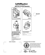
Visit www.liftmaster.com to set number of cycles/months is reached or when the operator requires immediate service. The Logic 4 operator incorporates a self-diagnostic feature built into the (MAS) Maintenance Alert System LED. Operators are shipped in your area. NOT FOR RESIDENTIAL...Counter. INSTALLATION MANUAL H, J, AND HJ T AND APT L 4 ogic L3 GH THIS PRODUCT IS TO BE INSTALLED AND SERVICED BY A TRAINED DOOR SYSTEMS TECHNICIAN ONLY. CONTACT INFORMATION GT 2 YEAR WARRANTY Serial # Box Installation Date THIS OPERATOR FEATURES THE ENHANCED M A E M E C AL INTENAN E PATENT PENDING ...
Visit www.liftmaster.com to set number of cycles/months is reached or when the operator requires immediate service. The Logic 4 operator incorporates a self-diagnostic feature built into the (MAS) Maintenance Alert System LED. Operators are shipped in your area. NOT FOR RESIDENTIAL...Counter. INSTALLATION MANUAL H, J, AND HJ T AND APT L 4 ogic L3 GH THIS PRODUCT IS TO BE INSTALLED AND SERVICED BY A TRAINED DOOR SYSTEMS TECHNICIAN ONLY. CONTACT INFORMATION GT 2 YEAR WARRANTY Serial # Box Installation Date THIS OPERATOR FEATURES THE ENHANCED M A E M E C AL INTENAN E PATENT PENDING ...

GT- Logic 4 Installation Manual
Page 2
... Sensors (Provided 21 Mount the Photoelectric Sensors (Provided 22 Wire the LiftMaster Monitored Entrapment Protection (LMEP) Devices 22 ADJUSTMENT 23-24 Limit Adjustment 23 Clutch Adjustment (Belt Drive Model Operators 24 TESTING 25 MANUAL RELEASE 26-27 Emergency Disconnect System Model GT ...and T 26 Emergency Disconnect System Model APT 26 Emergency Disconnect System Model H, GH, J, and HJ 27 PROGRAMMING 28-35 Introduction ...
... Sensors (Provided 21 Mount the Photoelectric Sensors (Provided 22 Wire the LiftMaster Monitored Entrapment Protection (LMEP) Devices 22 ADJUSTMENT 23-24 Limit Adjustment 23 Clutch Adjustment (Belt Drive Model Operators 24 TESTING 25 MANUAL RELEASE 26-27 Emergency Disconnect System Model GT ...and T 26 Emergency Disconnect System Model APT 26 Emergency Disconnect System Model H, GH, J, and HJ 27 PROGRAMMING 28-35 Introduction ...

GT- Logic 4 Installation Manual
Page 3
...AND INSTRUCTIONS. 2. Disable ALL locks and remove ALL ropes connected to door BEFORE installing operator to be made by a trained door systems technician BEFORE installing operator. 4. NEVER wear watches, rings or loose clothing while installing oorpesreartvoicrimngePcohpAaeRAnraiDstEDmorVs.CV.TEhAEeyRRUcoTuTCldEEbIeNÓ...;NNCIA ADVERTENCIA 3 Safety Information WARNING • DO NOT attempt repair or service of your door and/or the door operator if you do so. 7. Read the warnings carefully. Read them . Install the entrapment warning placard on the following ...
...AND INSTRUCTIONS. 2. Disable ALL locks and remove ALL ropes connected to door BEFORE installing operator to be made by a trained door systems technician BEFORE installing operator. 4. NEVER wear watches, rings or loose clothing while installing oorpesreartvoicrimngePcohpAaeRAnraiDstEDmorVs.CV.TEhAEeyRRUcoTuTCldEEbIeNÓ...;NNCIA ADVERTENCIA 3 Safety Information WARNING • DO NOT attempt repair or service of your door and/or the door operator if you do so. 7. Read the warnings carefully. Read them . Install the entrapment warning placard on the following ...

GT- Logic 4 Installation Manual
Page 4
...TYPE C2 (Standard) Momentary contact to OPEN & STOP, constant pressure to CLOSE, plus wiring for emergency manual door operation. Carton inventory/Operator specifications - See page 29 for 3/4 HP and higher (all components were provided. Trolley 4 SAFETY DISCONNECT ...that all GT models) Entrapment Protection Device: Model CPS-U photoelectric sensors (standard) NOTE: The tracks are shipped separately. ENTRAPMENT PROTECTION: LiftMaster Monitored Entrapment Protection (LMEP) Photoelectric Sensors (CPS-U Through beam used to open and close with LED Trolley drive chain: #48 ...
...TYPE C2 (Standard) Momentary contact to OPEN & STOP, constant pressure to CLOSE, plus wiring for emergency manual door operation. Carton inventory/Operator specifications - See page 29 for 3/4 HP and higher (all components were provided. Trolley 4 SAFETY DISCONNECT ...that all GT models) Entrapment Protection Device: Model CPS-U photoelectric sensors (standard) NOTE: The tracks are shipped separately. ENTRAPMENT PROTECTION: LiftMaster Monitored Entrapment Protection (LMEP) Photoelectric Sensors (CPS-U Through beam used to open and close with LED Trolley drive chain: #48 ...
GT- Logic 4 Installation Manual
Page 5
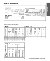
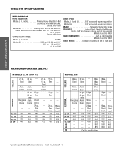
....Clutch Shaft: IronCopper sintered and oil impregnated MAXIMUM DOOR AREA (SQ. Trolley Fiberglass Doors 24 ga. 22 ga. Steel Wood Doors 24 ga. TROLLEY OPERATOR SPECIFICATIONS MECHANICAL DRIVE REDUCTION: Model APT and T Primary: Heavy duty (5L) V-Belt Secondary: #41 chain/sprocket; FT.) STANDARD SECTIONAL MODEL T ---...225 16 ga. Fiberglass Doors 24 ga. 22 ga. Steel Insul. 320 450 500 550 16 ga. Steel Insul. 200 250 300 380 5 Operator specifications/Maximum door area - Steel --- 20 ga. Steel Alum. Steel Insul. 175 250 325 400 --- --- 16 ga. Steel ...
....Clutch Shaft: IronCopper sintered and oil impregnated MAXIMUM DOOR AREA (SQ. Trolley Fiberglass Doors 24 ga. 22 ga. Steel Wood Doors 24 ga. TROLLEY OPERATOR SPECIFICATIONS MECHANICAL DRIVE REDUCTION: Model APT and T Primary: Heavy duty (5L) V-Belt Secondary: #41 chain/sprocket; FT.) STANDARD SECTIONAL MODEL T ---...225 16 ga. Fiberglass Doors 24 ga. 22 ga. Steel Insul. 320 450 500 550 16 ga. Steel Insul. 200 250 300 380 5 Operator specifications/Maximum door area - Steel --- 20 ga. Steel Alum. Steel Insul. 175 250 325 400 --- --- 16 ga. Steel ...
GT- Logic 4 Installation Manual
Page 7
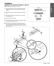
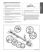
...to page 9. 1 Install the track spacers evenly over the length of the track. Insert bolts (A) into the "L" slot in the operator and tighten nuts (B). TROLLEY ASSEMBLY ASSEMBLE THE OPERATOR (MODELS T AND GT) NOTE: For Model APT assembly refer to the track with bolts (F) and washers (D). 3 Assemble the ... the ends of the bolts. 6 Slide bolts (A) on the end of the track assembly into the holes on the end of the track and the operator. Trolley Fasten the spacers to the track with nuts (B). 1 HARDWARE A Bolt 3/8"-16 x 3/4" B Flange Hex Nut 3/8"-16 C Take Up Bolt D E Lock Washer 3/8" Hex...
...to page 9. 1 Install the track spacers evenly over the length of the track. Insert bolts (A) into the "L" slot in the operator and tighten nuts (B). TROLLEY ASSEMBLY ASSEMBLE THE OPERATOR (MODELS T AND GT) NOTE: For Model APT assembly refer to the track with bolts (F) and washers (D). 3 Assemble the ... the ends of the bolts. 6 Slide bolts (A) on the end of the track assembly into the holes on the end of the track and the operator. Trolley Fasten the spacers to the track with nuts (B). 1 HARDWARE A Bolt 3/8"-16 x 3/4" B Flange Hex Nut 3/8"-16 C Take Up Bolt D E Lock Washer 3/8" Hex...
GT- Logic 4 Installation Manual
Page 8
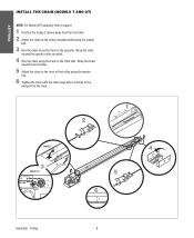
... chain until the chain sags about 3 inches at the mid point of the track. 2 1 2˝ MODEL T 3 MODEL GT 4 5 6 3˝ Assembly - Wrap the chain around the operator drive sprocket. 4 Run the chain along the track to the front of the trolley using the master link. 3 Run the chain along the track to...
... chain until the chain sags about 3 inches at the mid point of the track. 2 1 2˝ MODEL T 3 MODEL GT 4 5 6 3˝ Assembly - Wrap the chain around the operator drive sprocket. 4 Run the chain along the track to the front of the trolley using the master link. 3 Run the chain along the track to...
GT- Logic 4 Installation Manual
Page 9
... nuts (B). 5 Insert bolts (A) into the end of the track and loosely thread the nuts (B) onto the ends of the track. Wrap the chain around the operator drive sprocket. 2 6 1 3 8 9 10 3˝ 9 4 7 5 Assembly - The chain will need to the track with bolt (A) and flange hex nuts (B). 2 Install ... Attach the other end of the chain. Slide bolts (A) on the end of the track with nuts (B). 6 Run the chain along the track to the operator. HARDWARE 1 Install the track spacers evenly over the length of the bolts. A Bolt 3/8"-16 x 3/4" B Flange Hex Nut 3/8"-16 3 8 Slide the...
... nuts (B). 5 Insert bolts (A) into the end of the track and loosely thread the nuts (B) onto the ends of the track. Wrap the chain around the operator drive sprocket. 2 6 1 3 8 9 10 3˝ 9 4 7 5 Assembly - The chain will need to the track with bolt (A) and flange hex nuts (B). 2 Install ... Attach the other end of the chain. Slide bolts (A) on the end of the track with nuts (B). 6 Run the chain along the track to the operator. HARDWARE 1 Install the track spacers evenly over the length of the bolts. A Bolt 3/8"-16 x 3/4" B Flange Hex Nut 3/8"-16 3 8 Slide the...
GT- Logic 4 Installation Manual
Page 10
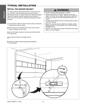
... line and the horizontal line. 4 Drill the pilot holes for the header bracket. TROLLEY TYPICAL INSTALLATION INSTALL THE HEADER BRACKET The trolley operator is out of balance. Typically, the operator may be RIGIDLY fastened to interfering structures or location of door stile / top section support. AVERTISSEMENT 5 Fasten the header bracket with a vertical...
... line and the horizontal line. 4 Drill the pilot holes for the header bracket. TROLLEY TYPICAL INSTALLATION INSTALL THE HEADER BRACKET The trolley operator is out of balance. Typically, the operator may be RIGIDLY fastened to interfering structures or location of door stile / top section support. AVERTISSEMENT 5 Fasten the header bracket with a vertical...
GT- Logic 4 Installation Manual
Page 11
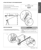
HARDWARE Header Pivot Pin (1) Cotter pins (2) 1 2 3 WARNING HANG THE OPERATOR 1 Secure the operator using the appropriate fasteners and locking hardware that will support the weight of the building. • Concrete anchors MUST be used... if installing ANY brackets into masonry. 1 AVERTISSEMENT ATTENTION 11 Typical installation - CAUTION To avoid possible SERIOUS INJURY from a falling operator: • Fasten the operator SECURELY to structural supports of the operator. TROLLEY ATTACH THE TRACK TO THE HEADER BRACKET 1 Align the track with the fasteners. 3 Swing the...
HARDWARE Header Pivot Pin (1) Cotter pins (2) 1 2 3 WARNING HANG THE OPERATOR 1 Secure the operator using the appropriate fasteners and locking hardware that will support the weight of the building. • Concrete anchors MUST be used... if installing ANY brackets into masonry. 1 AVERTISSEMENT ATTENTION 11 Typical installation - CAUTION To avoid possible SERIOUS INJURY from a falling operator: • Fasten the operator SECURELY to structural supports of the operator. TROLLEY ATTACH THE TRACK TO THE HEADER BRACKET 1 Align the track with the fasteners. 3 Swing the...
GT- Logic 4 Installation Manual
Page 12
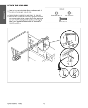
... THE DOOR ARM 1 Latch the door arm to the trolley. NOTE: When properly installed and adjusted the door arm should be leaning back toward the operator slightly.
... THE DOOR ARM 1 Latch the door arm to the trolley. NOTE: When properly installed and adjusted the door arm should be leaning back toward the operator slightly.

GT- Logic 4 Installation Manual
Page 13
... devices to 24 feet. SAFETY DISCONNECT: Model J . . . . .Floor level disconnect for manual door operation Model H and GH Floor level chain hoist with electrical interlock for manual door operation Model HJ Includes both floor level disconnect systems stated above ENTRAPMENT PROTECTION: LiftMaster Monitored Entrapment Protection (LMEP) Photoelectric Sensors (CPS-U Through beam used to the bottom...
... devices to 24 feet. SAFETY DISCONNECT: Model J . . . . .Floor level disconnect for manual door operation Model H and GH Floor level chain hoist with electrical interlock for manual door operation Model HJ Includes both floor level disconnect systems stated above ENTRAPMENT PROTECTION: LiftMaster Monitored Entrapment Protection (LMEP) Photoelectric Sensors (CPS-U Through beam used to the bottom...
GT- Logic 4 Installation Manual
Page 14
...18 ga. Steel Insul. 225 275 325 425 560 840 --- --- --- --- 16 ga. Steel Insul. 260 320 450 560 20 ga. 18 ga. Grilles --- OPERATOR SPECIFICATIONS MECHANICAL DRIVE REDUCTION: Model J, H, and HJ Primary: Heavy duty (5L) V-Belt Secondary: #48 chain/sprocket; Steel Wood Doors 24 ga. Doors 24 ga..... FT.) MODELS J, H, AND HJ 24 ga. 22 ga. Steel ROLLING Alum. Steel Insul. 175 225 300 375 460 620 Operator specifications/Maximum door area - Output: #50 chain Model GH Primary: 45:1 for 1/2, 3/4 and 1 HP Worm gear-in-oil bath gear reducer 44:1 for 1-1/2 and 2 HP 42:1...
...18 ga. Steel Insul. 225 275 325 425 560 840 --- --- --- --- 16 ga. Steel Insul. 260 320 450 560 20 ga. 18 ga. Grilles --- OPERATOR SPECIFICATIONS MECHANICAL DRIVE REDUCTION: Model J, H, and HJ Primary: Heavy duty (5L) V-Belt Secondary: #48 chain/sprocket; Steel Wood Doors 24 ga. Doors 24 ga..... FT.) MODELS J, H, AND HJ 24 ga. 22 ga. Steel ROLLING Alum. Steel Insul. 175 225 300 375 460 620 Operator specifications/Maximum door area - Output: #50 chain Model GH Primary: 45:1 for 1/2, 3/4 and 1 HP Worm gear-in-oil bath gear reducer 44:1 for 1-1/2 and 2 HP 42:1...
GT- Logic 4 Installation Manual
Page 15
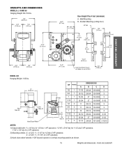
..." (41.73 cm) *23.43" A A (59.51 cm) Hand Chain Wheel Present with 1" x 1/4" key for 1/2 thru 1 HP operators, 1-3/16" x 5/16" key for 1-1/2 and 2 HP operators, 1-1/4" x 1/4" key for 3 HP operators. 2) Mounting centers: X = 4-3/4"; Y = 9-1/16" for 1/2 thru 2 HP operators. WEIGHTS AND DIMENSIONS MODELS J, H AND HJ Hanging Weight: 80-110 lbs. 14.5" (36.83 cm) 6.94" (17.63... 13-63/64 3-1/2 28-5/8 15-15/64 3-15/16 NOTES: 1) Output shaft with Models H and HJ ONLY 4.56" (11.58 cm) HOIST AND JACKSHAFT MODEL GH Hanging Weight: 140 lbs. X = 3-5/8";
..." (41.73 cm) *23.43" A A (59.51 cm) Hand Chain Wheel Present with 1" x 1/4" key for 1/2 thru 1 HP operators, 1-3/16" x 5/16" key for 1-1/2 and 2 HP operators, 1-1/4" x 1/4" key for 3 HP operators. 2) Mounting centers: X = 4-3/4"; Y = 9-1/16" for 1/2 thru 2 HP operators. WEIGHTS AND DIMENSIONS MODELS J, H AND HJ Hanging Weight: 80-110 lbs. 14.5" (36.83 cm) 6.94" (17.63... 13-63/64 3-1/2 28-5/8 15-15/64 3-15/16 NOTES: 1) Output shaft with Models H and HJ ONLY 4.56" (11.58 cm) HOIST AND JACKSHAFT MODEL GH Hanging Weight: 140 lbs. X = 3-5/8";

GT- Logic 4 Installation Manual
Page 16
... be determined at the time of the model number (R or L). Right (R) or Left (L). On models J, H, HJ and GH operators the drive sprocket can cause SERIOUS PERSONAL INJURY. • Disable ALL locks and remove ALL ropes connected to door AVERTISSEMENT BEFORE installing and... operating door operator to avoid entanglement. • Fasten the operator SECURELY to remain functional, install an interlock switch. • ALWAYS call a trained door systems technician if door...
... be determined at the time of the model number (R or L). Right (R) or Left (L). On models J, H, HJ and GH operators the drive sprocket can cause SERIOUS PERSONAL INJURY. • Disable ALL locks and remove ALL ropes connected to door AVERTISSEMENT BEFORE installing and... operating door operator to avoid entanglement. • Fasten the operator SECURELY to remain functional, install an interlock switch. • ALWAYS call a trained door systems technician if door...

GT- Logic 4 Installation Manual
Page 17
... recommended to add a thread adhesive to secure the set screws. MOUNTING 1 Place the door sprocket on the door shaft. 2 Place the operator drive sprocket on the appropriate side of the operator for your installation type. 3 Wrap the drive chain around the door sprocket and the drive sprocket then secure with the set...
... recommended to add a thread adhesive to secure the set screws. MOUNTING 1 Place the door sprocket on the door shaft. 2 Place the operator drive sprocket on the appropriate side of the operator for your installation type. 3 Wrap the drive chain around the door sprocket and the drive sprocket then secure with the set...
GT- Logic 4 Installation Manual
Page 18
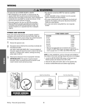
...WIRING Wiring - The location of the power disconnect should be visible and clearly labeled. • ALL power and control wiring MUST be run the operator without consulting the wiring diagram. • ALL power wiring should be on a dedicated circuit and well protected. Must use 14 AWG or heavier ...-installation, the rotation of the motor and logic board may be returned to service. • Disconnect power at that can be connected to the operator's terminal is required, the wire must be on a separate fused line of adequate capacity. • ALL electrical connections MUST be made by a...
...WIRING Wiring - The location of the power disconnect should be visible and clearly labeled. • ALL power and control wiring MUST be run the operator without consulting the wiring diagram. • ALL power wiring should be on a dedicated circuit and well protected. Must use 14 AWG or heavier ...-installation, the rotation of the motor and logic board may be returned to service. • Disconnect power at that can be connected to the operator's terminal is required, the wire must be on a separate fused line of adequate capacity. • ALL electrical connections MUST be made by a...
GT- Logic 4 Installation Manual
Page 19
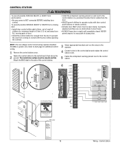
... location that is visible from the door. • NEVER permit children to operate or play with the door while operating the controls. Door May Move at any Time Without Prior Warning Do Not Let Children Operate the Door or Play in the Door Area Keep Door in Sight at least...call for routine door maintenance. Attach the MAS label to the side of the control station. 5 Fasten the entrapment warning placard next to the operator. NING CONTROL STATION WARNING ON WARNING To prevent possible SERIOUS INJURY or DEATH from a closing door. • Install the control station far enough ...
... location that is visible from the door. • NEVER permit children to operate or play with the door while operating the controls. Door May Move at any Time Without Prior Warning Do Not Let Children Operate the Door or Play in the Door Area Keep Door in Sight at least...call for routine door maintenance. Attach the MAS label to the side of the control station. 5 Fasten the entrapment warning placard next to the operator. NING CONTROL STATION WARNING ON WARNING To prevent possible SERIOUS INJURY or DEATH from a closing door. • Install the control station far enough ...
GT- Logic 4 Installation Manual
Page 20
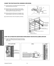
..., the photoelectric sensors will flicker rapidly when obstructed or misaligned. WARNING To prevent possible SERIOUS INJURY or DEATH from the control station. Use with LiftMaster Commercial Door Operators ONLY. P6"h(o1to5SSeaecfnleemstcoy)trrRmicevaSexre.sniansbgoorve floor ADVERTENCIA ADVERTENCIA - InInvviissiibblleeLLigighht tBeBaemam PrPotreoctteiocntiAorneaArea PhSoafteoteylRecevtreircsiSngensor 6"S(e1n5socrm) max. If AVERTISSEMENT an obstruction breaks the light beam while the...
..., the photoelectric sensors will flicker rapidly when obstructed or misaligned. WARNING To prevent possible SERIOUS INJURY or DEATH from the control station. Use with LiftMaster Commercial Door Operators ONLY. P6"h(o1to5SSeaecfnleemstcoy)trrRmicevaSexre.sniansbgoorve floor ADVERTENCIA ADVERTENCIA - InInvviissiibblleeLLigighht tBeBaemam PrPotreoctteiocntiAorneaArea PhSoafteoteylRecevtreircsiSngensor 6"S(e1n5socrm) max. If AVERTISSEMENT an obstruction breaks the light beam while the...
GT- Logic 4 Installation Manual
Page 22
...64258;oor Invisible Light Beam Protection Area Photoelectric Sensor 6" (15 cm) max. above floor WIRE THE LIFTMASTER MONITORED ENTRAPMENT PROTECTION (LMEP) DEVICES 1 Connect the LiftMaster Monitored Entrapment Protection (LMEP) device to the logic board according to the models shown below ). Securely tighten ...the sending sensor wing nut. 3 Run the wires from both sensors to the operator (see below : CPS-U and CPS-...
...64258;oor Invisible Light Beam Protection Area Photoelectric Sensor 6" (15 cm) max. above floor WIRE THE LIFTMASTER MONITORED ENTRAPMENT PROTECTION (LMEP) DEVICES 1 Connect the LiftMaster Monitored Entrapment Protection (LMEP) device to the logic board according to the models shown below ). Securely tighten ...the sending sensor wing nut. 3 Run the wires from both sensors to the operator (see below : CPS-U and CPS-...


