
GT- Logic 4 Installation Manual
Page 1
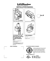
...set an internal Maintenance Cycle Counter. Operators are shipped in your area. Visit www.liftmaster.com to set number of cycles/months is reached or when the operator requires immediate service. The Logic 4 operator incorporates a self-diagnostic feature built into the (MAS) Maintenance Alert System ...LED. INSTALLATION MANUAL H, J, AND HJ T AND APT L 4 ogic L3 GH THIS PRODUCT IS TO BE INSTALLED AND SERVICED BY A ...
...set an internal Maintenance Cycle Counter. Operators are shipped in your area. Visit www.liftmaster.com to set number of cycles/months is reached or when the operator requires immediate service. The Logic 4 operator incorporates a self-diagnostic feature built into the (MAS) Maintenance Alert System ...LED. INSTALLATION MANUAL H, J, AND HJ T AND APT L 4 ogic L3 GH THIS PRODUCT IS TO BE INSTALLED AND SERVICED BY A ...

GT- Logic 4 Installation Manual
Page 2
... Control Station 19 ENTRAPMENT PROTECTION 20-22 LiftMaster Monitored Entrapment Protection (LMEP 20 Install the Photoelectric Sensors (Provided 21 Mount ... and T 26 Emergency Disconnect System Model APT 26 Emergency Disconnect System Model H, GH, J, and HJ 27 PROGRAMMING 28-35 Introduction to Order Repair Parts 36 TROUBLESHOOTING... Guide 38 Troubleshooting Error Codes 39 Troubleshooting Radio Functionality 40 WIRING DIAGRAMS 41-42 Logic (Ver. 4.0) 1 Phase Wiring Diagram 41 Logic (Ver. 4.0) 3 Phase Wiring Diagram 42 ACCESSORIES 43 CONTROL CONNECTION DIAGRAM BACK ...
... Control Station 19 ENTRAPMENT PROTECTION 20-22 LiftMaster Monitored Entrapment Protection (LMEP 20 Install the Photoelectric Sensors (Provided 21 Mount ... and T 26 Emergency Disconnect System Model APT 26 Emergency Disconnect System Model H, GH, J, and HJ 27 PROGRAMMING 28-35 Introduction to Order Repair Parts 36 TROUBLESHOOTING... Guide 38 Troubleshooting Error Codes 39 Troubleshooting Radio Functionality 40 WIRING DIAGRAMS 41-42 Logic (Ver. 4.0) 1 Phase Wiring Diagram 41 Logic (Ver. 4.0) 3 Phase Wiring Diagram 42 ACCESSORIES 43 CONTROL CONNECTION DIAGRAM BACK ...
GT- Logic 4 Installation Manual
Page 18
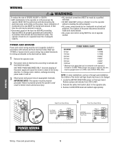
... injury. Failure to REV. 2. Must use 14 AWG or heavier wire for wiring as a through-wall-installation, the rotation of the motor and logic board may be changed. 1. IMPORTANT NOTE: This operator must be on a separate fused line of adequate capacity. • ALL electrical connections MUST...wiring MUST be run in separate conduit in accordance with national and local electrical codes. NOTE: In some installations, such as indicated on the logic board. When a larger wire gauge is 12 AWG. WIRING WARNING To reduce the risk of SEVERE INJURY or DEATH: • ANY ...
... injury. Failure to REV. 2. Must use 14 AWG or heavier wire for wiring as a through-wall-installation, the rotation of the motor and logic board may be changed. 1. IMPORTANT NOTE: This operator must be on a separate fused line of adequate capacity. • ALL electrical connections MUST...wiring MUST be run in separate conduit in accordance with national and local electrical codes. NOTE: In some installations, such as indicated on the logic board. When a larger wire gauge is 12 AWG. WIRING WARNING To reduce the risk of SEVERE INJURY or DEATH: • ANY ...
GT- Logic 4 Installation Manual
Page 22
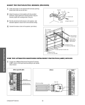
above floor WIRE THE LIFTMASTER MONITORED ENTRAPMENT PROTECTION (LMEP) DEVICES 1 Connect the LiftMaster Monitored Entrapment Protection (LMEP) device to the logic board according to following page) Photoelectric Sensor 6" (15 cm) max. Bell Wire Wing Nut "C" Wrap Wire Indicator Light Sensor Hex Bolt 1/4-20x1-1/2" ENTRAPMENT PROTECTION Secure ...
above floor WIRE THE LIFTMASTER MONITORED ENTRAPMENT PROTECTION (LMEP) DEVICES 1 Connect the LiftMaster Monitored Entrapment Protection (LMEP) device to the logic board according to following page) Photoelectric Sensor 6" (15 cm) max. Bell Wire Wing Nut "C" Wrap Wire Indicator Light Sensor Hex Bolt 1/4-20x1-1/2" ENTRAPMENT PROTECTION Secure ...
GT- Logic 4 Installation Manual
Page 23
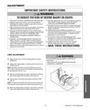
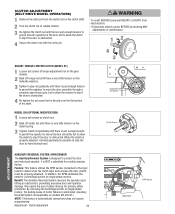
... in motion and ALWAYS keep remote controls out of reach of the limit nuts. NOTE: The Open Limit Switch (OLS) LED on the logic board will illuminate when the switches are made by a trained door systems technician. 12. WARNING ADJUSTMENT IMPORTANT SAFETY INSTRUCTIONS WARNING TO REDUCE THE... or remote controls. 3. Failure to door travel. 4. NOTE: The Close Limit Switch (CLS) and Safety Limit Switch (SLS) LEDs on the logic board will ATTENTION illuminate when the switches are activated and the power is on . 3 When the retaining plate is released, verify that the retaining ...
... in motion and ALWAYS keep remote controls out of reach of the limit nuts. NOTE: The Open Limit Switch (OLS) LED on the logic board will illuminate when the switches are made by a trained door systems technician. 12. WARNING ADJUSTMENT IMPORTANT SAFETY INSTRUCTIONS WARNING TO REDUCE THE... or remote controls. 3. Failure to door travel. 4. NOTE: The Close Limit Switch (CLS) and Safety Limit Switch (SLS) LEDs on the logic board will ATTENTION illuminate when the switches are activated and the power is on . 3 When the retaining plate is released, verify that the retaining ...
GT- Logic 4 Installation Manual
Page 24
... the door is obstructed. 4 Re-tighten the set screws on clutch nut. Feature: This feature utilizes the RPM sensor connected to the logic board to detect when the clutch slips and reverses the door (clutch must be possible to stop the door by hand during travel. (3)...automatically learned and does not require programming. We require the use of the shaft. Clutch adjustment 24 LOSE OPEN RPM Sensor Logic Board AVERTISSEMENT Torque Nut Set Screws MODEL GH (OPTIONAL MODIFICATION) 1 Loosen set screw that is directly over the flat portion of safety devices for primary safety...
... the door is obstructed. 4 Re-tighten the set screws on clutch nut. Feature: This feature utilizes the RPM sensor connected to the logic board to detect when the clutch slips and reverses the door (clutch must be possible to stop the door by hand during travel. (3)...automatically learned and does not require programming. We require the use of the shaft. Clutch adjustment 24 LOSE OPEN RPM Sensor Logic Board AVERTISSEMENT Torque Nut Set Screws MODEL GH (OPTIONAL MODIFICATION) 1 Loosen set screw that is directly over the flat portion of safety devices for primary safety...
GT- Logic 4 Installation Manual
Page 25
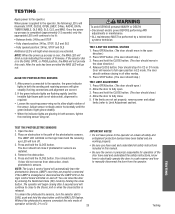
... 1. The door should not close . 5. The door should continue closing after 5 seconds and will reverse to fully open direction.) 2. NOTE: The Logic 4 control board will automatically learn the photoelectric sensors (LMEP) once they are installed. 4. To unlearn the photoelectric sensors, turn off . Release CLOSE ..., tighten the receiving sensor wing nut. Door will continue to close button is misaligned or disconnected the LMEP LED on the logic control board will turn the selector dial to the operator, the green indicator lights in E2 mode. Press STOP buAttonV. (...
... 1. The door should not close . 5. The door should continue closing after 5 seconds and will reverse to fully open direction.) 2. NOTE: The Logic 4 control board will automatically learn the photoelectric sensors (LMEP) once they are installed. 4. To unlearn the photoelectric sensors, turn off . Release CLOSE ..., tighten the receiving sensor wing nut. Door will continue to close button is misaligned or disconnected the LMEP LED on the logic control board will turn the selector dial to the operator, the green indicator lights in E2 mode. Press STOP buAttonV. (...
GT- Logic 4 Installation Manual
Page 28
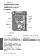
...Close Button Stop Button Control Wiring Terminal Block Selector Dial (used for limit switch adjustment instructions. Refer to the Entrapment Protection section. LOGIC BOARD PUSH BUTTONS (OPEN, CLOSE, STOP) Open, Close and Stop buttons are Open Limit Switch (OLS), Close Limit Switch (...CLS) and Sensing Limit Switch (SLS). PROGRAMMING Programming-Introduction to function. PROGRAMMING INTRODUCTION TO PROGRAMMING Many programmable functions require that a LiftMaster Entrapment Protection (LMEP) device be installed in the DIAG, OPTN, or PROG position, the MAS will go out. LEDs on board...
...Close Button Stop Button Control Wiring Terminal Block Selector Dial (used for limit switch adjustment instructions. Refer to the Entrapment Protection section. LOGIC BOARD PUSH BUTTONS (OPEN, CLOSE, STOP) Open, Close and Stop buttons are Open Limit Switch (OLS), Close Limit Switch (...CLS) and Sensing Limit Switch (SLS). PROGRAMMING Programming-Introduction to function. PROGRAMMING INTRODUCTION TO PROGRAMMING Many programmable functions require that a LiftMaster Entrapment Protection (LMEP) device be installed in the DIAG, OPTN, or PROG position, the MAS will go out. LEDs on board...
GT- Logic 4 Installation Manual
Page 30
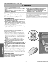
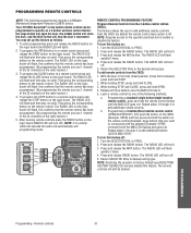
...is subject to the following two conditions: (1) this device may cause undesired operation. Press and release the RADIO button on the logic board until completely closed. ERASING REMOTE CONTROLS Press and hold the remote control button until the RADIO LED flashes rapidly. ADVERTENCIA ...mode, operation is performed within 30 seconds. PROGRAMMING REMOTE CONTROLS WARNING To prevent possible SEVERE INJURY or DEATH: CAUTION • Install a LiftMaster Monitored Entrapment Protection (LMEP) • Activate door ONLY when it can be seen clearly, is OPEN/STOP/CLOSE/REVERSE/ STOP and...
...is subject to the following two conditions: (1) this device may cause undesired operation. Press and release the RADIO button on the logic board until completely closed. ERASING REMOTE CONTROLS Press and hold the remote control button until the RADIO LED flashes rapidly. ADVERTENCIA ...mode, operation is performed within 30 seconds. PROGRAMMING REMOTE CONTROLS WARNING To prevent possible SEVERE INJURY or DEATH: CAUTION • Install a LiftMaster Monitored Entrapment Protection (LMEP) • Activate door ONLY when it can be seen clearly, is OPEN/STOP/CLOSE/REVERSE/ STOP and...
GT- Logic 4 Installation Manual
Page 31
...By programming the remote you use 1 channel of the 23 channels on the logic board (the RADIO LED will also disable this confirms that you use 1 channel of the following programming requires a LiftMaster Monitored Entrapment Protection (LMEP) device. The RADIO LED will flash and then ...stay on the radio receiver.) 3. Then press the corresponding button on the logic board. The RADIO LED will flash and then stay on...
...By programming the remote you use 1 channel of the 23 channels on the logic board (the RADIO LED will also disable this confirms that you use 1 channel of the following programming requires a LiftMaster Monitored Entrapment Protection (LMEP) device. The RADIO LED will flash and then ...stay on the radio receiver.) 3. Then press the corresponding button on the logic board. The RADIO LED will flash and then stay on...
GT- Logic 4 Installation Manual
Page 32
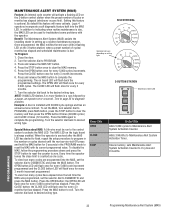
... selector dial back to the desired wiring type. Turn the selector dial back to desired wiring type. The MAS LED on the logic board is optional. Press the OPEN button; Logic 4 operators incorporate a self diagnostic feature built into the MAS, set the selector dial to Maintenance Alert System Activation Counter. Once programmed...
... selector dial back to the desired wiring type. Turn the selector dial back to desired wiring type. The MAS LED on the logic board is optional. Press the OPEN button; Logic 4 operators incorporate a self diagnostic feature built into the MAS, set the selector dial to Maintenance Alert System Activation Counter. Once programmed...
GT- Logic 4 Installation Manual
Page 33
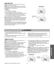
... the TIMER button, press and TO PROGRAM MANUALLY (METHOD 1): release the STOP button to PROGRAM. 3. Press and release the TIMER button on logic board. 4. AVER PROGRAMMING 5. OPEN MID STOP Feature: The Mid Stop feature is properly adjusted and there are no obstructions to door travel. ...wiring type T E2 D1 C2 B2 TS FSTS DIAG OPTN PROG WARNING To prevent possible SEVERE INJURY or DEATH: CAUTION • Install a LiftMaster Monitored Entrapment Protection (LMEP) device. • Activate door ONLY when it can be unobstructed. automatically after preset time. Turn the selector ...
... the TIMER button, press and TO PROGRAM MANUALLY (METHOD 1): release the STOP button to PROGRAM. 3. Press and release the TIMER button on logic board. 4. AVER PROGRAMMING 5. OPEN MID STOP Feature: The Mid Stop feature is properly adjusted and there are no obstructions to door travel. ...wiring type T E2 D1 C2 B2 TS FSTS DIAG OPTN PROG WARNING To prevent possible SEVERE INJURY or DEATH: CAUTION • Install a LiftMaster Monitored Entrapment Protection (LMEP) device. • Activate door ONLY when it can be unobstructed. automatically after preset time. Turn the selector ...
GT- Logic 4 Installation Manual
Page 35
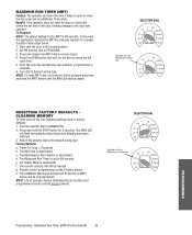
...NOTE: Life of the user installed settings back to reach the full open or close limit within the set to desired wiring type. The LiftMaster Monitored Entrapment Protection (LMEP) device will still be manually learned for the door to factory defaults: 1. Maximum Run Timer (MRT)/Factory defaults... position. 2. The Maximum Run Timer is deactivated d. MAXIMUM RUN TIMER (MRT) Feature: The operator can learn the time it will vary depending on logic board. 4. In the event the application requires the MRT be learned g. NOTE: To reset MRT only, turn selector dial to open limit. 5....
...NOTE: Life of the user installed settings back to reach the full open or close limit within the set to desired wiring type. The LiftMaster Monitored Entrapment Protection (LMEP) device will still be manually learned for the door to factory defaults: 1. Maximum Run Timer (MRT)/Factory defaults... position. 2. The Maximum Run Timer is deactivated d. MAXIMUM RUN TIMER (MRT) Feature: The operator can learn the time it will vary depending on logic board. 4. In the event the application requires the MRT be learned g. NOTE: To reset MRT only, turn selector dial to open limit. 5....

GT- Logic 4 Installation Manual
Page 36
... LARGE SERVICE ORGANIZATION SPANS AMERICA Installation and service information are rated for some models. Press and release the MAS button on the logic board. 5. Return the SELECTOR DIAL to DIAG (diagnostic mode). 3. z Inspect and service whenever a malfunction is adjusted at ...800-528-2806 www.liftmaster.com LIFAEDOVFEORPETREATNOCRIFAEATURE (ODOMETER/CYCLE COUNATEDR)VERTENCIA The operator is available as an option for continuous operation. • Do not lubricate clutch or V-belt. Repeat ALL procedures. Press and release the MRT button on the logic board. 4. NOTE...
... LARGE SERVICE ORGANIZATION SPANS AMERICA Installation and service information are rated for some models. Press and release the MAS button on the logic board. 5. Return the SELECTOR DIAL to DIAG (diagnostic mode). 3. z Inspect and service whenever a malfunction is adjusted at ...800-528-2806 www.liftmaster.com LIFAEDOVFEORPETREATNOCRIFAEATURE (ODOMETER/CYCLE COUNATEDR)VERTENCIA The operator is available as an option for continuous operation. • Do not lubricate clutch or V-belt. Repeat ALL procedures. Press and release the MRT button on the logic board. 4. NOTE...
GT- Logic 4 Installation Manual
Page 37
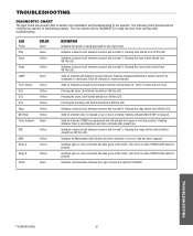
... common and terminal 6. Indicates a closed circuit between common and terminal 12. Pressing the Open Limit Switch should turn ON this LED. TROUBLESHOOTING DIAGNOSTIC CHART The logic board has several LEDs to assist in verifying the operator is functioning properly. Indicates open or close . LED turns on indicates a closed circuit between the...
... common and terminal 6. Indicates a closed circuit between common and terminal 12. Pressing the Open Limit Switch should turn ON this LED. TROUBLESHOOTING DIAGNOSTIC CHART The logic board has several LEDs to assist in verifying the operator is functioning properly. Indicates open or close . LED turns on indicates a closed circuit between the...

GT- Logic 4 Installation Manual
Page 38
...ONLY CLOSE AFTER other sensing device is obstructed A FIVE SECOND DELAY or activated WITH CONSTANT PRESSURE ON THE CLOSE b) The logic board thinks that RPM wheel is turning when operator is not engaged. TROUBLESHOOTING 38 Troubleshooting guide Allow motor to cool before attempting...is malfunctioning f) Motor thermal overload tripped g) Possible accessory malfunction h) Off Board relay may need to be replaced see wiring diagram i) Possible logic board failure ➤ Verify primary line voltage from the memory by resetting factory defaults. Green LED next to stop button must be on...
...ONLY CLOSE AFTER other sensing device is obstructed A FIVE SECOND DELAY or activated WITH CONSTANT PRESSURE ON THE CLOSE b) The logic board thinks that RPM wheel is turning when operator is not engaged. TROUBLESHOOTING 38 Troubleshooting guide Allow motor to cool before attempting...is malfunctioning f) Motor thermal overload tripped g) Possible accessory malfunction h) Off Board relay may need to be replaced see wiring diagram i) Possible logic board failure ➤ Verify primary line voltage from the memory by resetting factory defaults. Green LED next to stop button must be on...

GT- Logic 4 Installation Manual
Page 39
... button on 3-button station Stuck button must be cleared. Operator must run as long as an input. TROUBLESHOOTING ERROR CODES Logic 4.0 operators incorporate a self diagnostic feature built into option card receptacles LiftMaster Monitored Entrapment Protection (LMEP) device faulted or removed for greater than 2 minutes Brownout Detected Flash on and off rapidly, the...
... button on 3-button station Stuck button must be cleared. Operator must run as long as an input. TROUBLESHOOTING ERROR CODES Logic 4.0 operators incorporate a self diagnostic feature built into option card receptacles LiftMaster Monitored Entrapment Protection (LMEP) device faulted or removed for greater than 2 minutes Brownout Detected Flash on and off rapidly, the...
GT- Logic 4 Installation Manual
Page 41
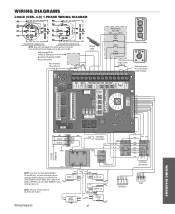
...2 3 4 RPM Board R1 R2 R3 Radio WIRING DIAGRAMS Refer to NO on Bypass L/S and to page 26 for H and HJ right hand models and all GH and J models. White wires connect the COM on BYPASS L/S and LOCK SENSOR switch to NC on Open L/S. (WH) (RD) (PU) (WH) COM ... wire from main harness connects to NC on LOCK SENSOR switch. WIRING DIAGRAMS LOGIC (VER. 4.0) 1 PHASE WIRING DIAGRAM 115V MOTOR CONNECTION 230V MOTOR CONNECTION NOTE: Gray (GY) and purple (PU) motor wires are reversed for LiftMaster Monitored Entrapment Protection (LMEP) device connections Hoist Interlock When Present TMR DEF ...
...2 3 4 RPM Board R1 R2 R3 Radio WIRING DIAGRAMS Refer to NO on Bypass L/S and to page 26 for H and HJ right hand models and all GH and J models. White wires connect the COM on BYPASS L/S and LOCK SENSOR switch to NC on Open L/S. (WH) (RD) (PU) (WH) COM ... wire from main harness connects to NC on LOCK SENSOR switch. WIRING DIAGRAMS LOGIC (VER. 4.0) 1 PHASE WIRING DIAGRAM 115V MOTOR CONNECTION 230V MOTOR CONNECTION NOTE: Gray (GY) and purple (PU) motor wires are reversed for LiftMaster Monitored Entrapment Protection (LMEP) device connections Hoist Interlock When Present TMR DEF ...
GT- Logic 4 Installation Manual
Page 42
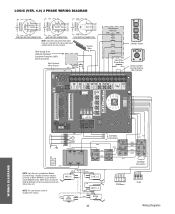
... L/S and to page 26 for H and HJ right hand models and all GH and J models. POWER IN NOTE: Lock Sensor is located in the chassis.... (PU) (OR) 01 A 48 26 (GY) (YE) See Motor Connections R1 R2 R3 Radio Wiring Diagrams WIRING DIAGRAMS LOGIC (VER. 4.0) 3 PHASE WIRING DIAGRAM 230V BRAKE (WHEN PRESENT) 230V BRAKE (WHEN PRESENT) 575V BRAKE (WHEN PRESENT) T4 T7...MOTOR CONNECTION 575V MOTOR CONNECTION NOTE: Gray (GY) and purple (PU) motor wires are reversed for LiftMaster Monitored Entrapment Protection (LMEP) device connections Hoist Interlock When Present TMR DEF (BL) SWITCH (YE) ...
... L/S and to page 26 for H and HJ right hand models and all GH and J models. POWER IN NOTE: Lock Sensor is located in the chassis.... (PU) (OR) 01 A 48 26 (GY) (YE) See Motor Connections R1 R2 R3 Radio Wiring Diagrams WIRING DIAGRAMS LOGIC (VER. 4.0) 3 PHASE WIRING DIAGRAM 230V BRAKE (WHEN PRESENT) 230V BRAKE (WHEN PRESENT) 575V BRAKE (WHEN PRESENT) T4 T7...MOTOR CONNECTION 575V MOTOR CONNECTION NOTE: Gray (GY) and purple (PU) motor wires are reversed for LiftMaster Monitored Entrapment Protection (LMEP) device connections Hoist Interlock When Present TMR DEF (BL) SWITCH (YE) ...
GT- Logic 4 Installation Manual
Page 43
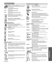
...or horizontal mount on either front or top of coil on a rolling door. OPEN CPS3CARD Option Logic Board: For use with adapter plate to construct a bottom bar on rolling doors. see below).... doors. Recommended to properly tension drive chain between L-shaped angles used with wall-mounted J, H, GH, DH or DJ operators. Single to provide special timer functions. MOUNTING BRACKETS 10-12360 Heavy gauge...-packaged with Maintenance Alert System. OPEN ACCESSORIES REMOTE CONTROLS 315MHz LiftMaster offers a variety of SECURITY✚® Remote Controls for your authorized dealer. Measures 31" x 19" x 18"...
...or horizontal mount on either front or top of coil on a rolling door. OPEN CPS3CARD Option Logic Board: For use with adapter plate to construct a bottom bar on rolling doors. see below).... doors. Recommended to properly tension drive chain between L-shaped angles used with wall-mounted J, H, GH, DH or DJ operators. Single to provide special timer functions. MOUNTING BRACKETS 10-12360 Heavy gauge...-packaged with Maintenance Alert System. OPEN ACCESSORIES REMOTE CONTROLS 315MHz LiftMaster offers a variety of SECURITY✚® Remote Controls for your authorized dealer. Measures 31" x 19" x 18"...

