
GT- Logic 4 Installation Manual
Page 1
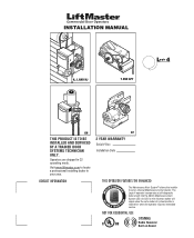
INSTALLATION MANUAL H, J, AND HJ T AND APT L 4 ogic L3 GH THIS PRODUCT IS TO BE INSTALLED AND SERVICED BY A TRAINED DOOR SYSTEMS TECHNICIAN ONLY. CONTACT INFORMATION GT 2 YEAR WARRANTY Serial # Box Installation Date THIS OPERATOR FEATURES THE ENHANCED M A E M E C AL INTENAN E PATENT PENDING R T T SYS The ...the set an internal Maintenance Cycle Counter. The Logic 4 operator incorporates a self-diagnostic feature built into the (MAS) Maintenance Alert System LED. Operators are shipped in your area. Visit www.liftmaster.com to set number of cycles/months is reached or ...
INSTALLATION MANUAL H, J, AND HJ T AND APT L 4 ogic L3 GH THIS PRODUCT IS TO BE INSTALLED AND SERVICED BY A TRAINED DOOR SYSTEMS TECHNICIAN ONLY. CONTACT INFORMATION GT 2 YEAR WARRANTY Serial # Box Installation Date THIS OPERATOR FEATURES THE ENHANCED M A E M E C AL INTENAN E PATENT PENDING R T T SYS The ...the set an internal Maintenance Cycle Counter. The Logic 4 operator incorporates a self-diagnostic feature built into the (MAS) Maintenance Alert System LED. Operators are shipped in your area. Visit www.liftmaster.com to set number of cycles/months is reached or ...

GT- Logic 4 Installation Manual
Page 2
...Provided 21 Mount the Photoelectric Sensors (Provided 22 Wire the LiftMaster Monitored Entrapment Protection (LMEP) Devices 22 ADJUSTMENT 23-24 Limit Adjustment 23 Clutch Adjustment (Belt Drive Model Operators 24 TESTING 25 MANUAL RELEASE 26-27 Emergency Disconnect System Model GT and T ...26 Emergency Disconnect System Model APT 26 Emergency Disconnect System Model H, GH, J, and HJ 27 PROGRAMMING 28-35 Introduction to...
...Provided 21 Mount the Photoelectric Sensors (Provided 22 Wire the LiftMaster Monitored Entrapment Protection (LMEP) Devices 22 ADJUSTMENT 23-24 Limit Adjustment 23 Clutch Adjustment (Belt Drive Model Operators 24 TESTING 25 MANUAL RELEASE 26-27 Emergency Disconnect System Model GT and T ...26 Emergency Disconnect System Model APT 26 Emergency Disconnect System Model H, GH, J, and HJ 27 PROGRAMMING 28-35 Introduction to...
GT- Logic 4 Installation Manual
Page 3
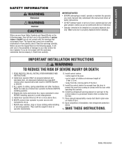
... do not comply with the door while operating the controls. 10. Install the entrapment warning placard on the following pages, it will alert you to the possibility of serious injury or death if you do not comply with the warnings that accompany it. Place manual release/safety reverse test label in contact...
... do not comply with the door while operating the controls. 10. Install the entrapment warning placard on the following pages, it will alert you to the possibility of serious injury or death if you do not comply with the warnings that accompany it. Place manual release/safety reverse test label in contact...

GT- Logic 4 Installation Manual
Page 4
DESCRIPTION Powerhead assembly Owner's manual and caution labels Hardware box (includes ...edge of door. LIMIT ADJUST Linear driven, fully adjustable screw type cams. Adjustable to provide non-contact safety protection. OPERATOR SPECIFICATIONS MOTOR TYPE Continuous duty HORSEPOWER: Model APT 1/2 HP Model GT 1/2, 3/4, 1 and 1-1/2 HP Model T... pressure to CLOSE, plus wiring for 3/4 HP and higher (all components were provided. ENTRAPMENT PROTECTION: LiftMaster Monitored Entrapment Protection (LMEP) Photoelectric Sensors (CPS-U Through beam used to 24 feet. Safety Edge (...
DESCRIPTION Powerhead assembly Owner's manual and caution labels Hardware box (includes ...edge of door. LIMIT ADJUST Linear driven, fully adjustable screw type cams. Adjustable to provide non-contact safety protection. OPERATOR SPECIFICATIONS MOTOR TYPE Continuous duty HORSEPOWER: Model APT 1/2 HP Model GT 1/2, 3/4, 1 and 1-1/2 HP Model T... pressure to CLOSE, plus wiring for 3/4 HP and higher (all components were provided. ENTRAPMENT PROTECTION: LiftMaster Monitored Entrapment Protection (LMEP) Photoelectric Sensors (CPS-U Through beam used to 24 feet. Safety Edge (...

GT- Logic 4 Installation Manual
Page 13
SAFETY DISCONNECT: Model J . . . . .Floor level disconnect for manual door operation Model H and GH Floor level chain hoist with open and close with electrical interlock for manual door operation Model HJ Includes both floor level disconnect systems stated above ENTRAPMENT PROTECTION: LiftMaster Monitored Entrapment Protection (LMEP) Photoelectric Sensors (CPS-U Through beam used to open override. ELECTRICAL TRANSFORMER 24Vac...
SAFETY DISCONNECT: Model J . . . . .Floor level disconnect for manual door operation Model H and GH Floor level chain hoist with open and close with electrical interlock for manual door operation Model HJ Includes both floor level disconnect systems stated above ENTRAPMENT PROTECTION: LiftMaster Monitored Entrapment Protection (LMEP) Photoelectric Sensors (CPS-U Through beam used to open override. ELECTRICAL TRANSFORMER 24Vac...

GT- Logic 4 Installation Manual
Page 16
...GH operators the drive sprocket can cause SERIOUS PERSONAL INJURY. • Disable ALL locks and remove ALL ropes connected to door AVERTISSEMENT BEFORE installing and operating door operator to avoid entanglement. • Fasten the operator SECURELY to structural supports of the AVERTISSEMENT building. • Concrete anchors MUST be fastened securely and with manual... hand chain systems, the handing of the operator must : a. Hoist and Jackshaft 16 12" - 15" ASSWEMARBLNYING WARNING CAUTION ASSEMBLE THE OPERATOR It is indicated by the last...
...GH operators the drive sprocket can cause SERIOUS PERSONAL INJURY. • Disable ALL locks and remove ALL ropes connected to door AVERTISSEMENT BEFORE installing and operating door operator to avoid entanglement. • Fasten the operator SECURELY to structural supports of the AVERTISSEMENT building. • Concrete anchors MUST be fastened securely and with manual... hand chain systems, the handing of the operator must : a. Hoist and Jackshaft 16 12" - 15" ASSWEMARBLNYING WARNING CAUTION ASSEMBLE THE OPERATOR It is indicated by the last...

GT- Logic 4 Installation Manual
Page 17
...and the drive sprockets. Hoist and Jackshaft MOUNTING 1 Place the door sprocket on the door shaft. 2 Place the operator drive sprocket on the appropriate side of the operator for your installation type. 3 Wrap the drive chain around the door sprocket and the drive sprocket then secure with... the set screws in place. 1 4 3 2 HOIST AND JACKSHAFT INSTALL THE MANUAL DISCONNECT 1 Fasten Door retaining bracket 4 feet above the &#...
...and the drive sprockets. Hoist and Jackshaft MOUNTING 1 Place the door sprocket on the door shaft. 2 Place the operator drive sprocket on the appropriate side of the operator for your installation type. 3 Wrap the drive chain around the door sprocket and the drive sprocket then secure with... the set screws in place. 1 4 3 2 HOIST AND JACKSHAFT INSTALL THE MANUAL DISCONNECT 1 Fasten Door retaining bracket 4 feet above the &#...
GT- Logic 4 Installation Manual
Page 23
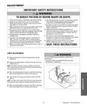
...retaining plate (1) and move the limit nut to operate or play with the notches of which are made by a trained door systems technician. 12. NEVER use manual release handle to set the OPEN limit (3). Failure to adjust the operator properly may cause SEVERE INJURY and DEATH. 10. ...Entrapment Protection device MUST be tested. See door manufacturer's owners manual. 11. SAVE THESE INSTRUCTIONS. ONLY activate door...
...retaining plate (1) and move the limit nut to operate or play with the notches of which are made by a trained door systems technician. 12. NEVER use manual release handle to set the OPEN limit (3). Failure to adjust the operator properly may cause SEVERE INJURY and DEATH. 10. ...Entrapment Protection device MUST be tested. See door manufacturer's owners manual. 11. SAVE THESE INSTRUCTIONS. ONLY activate door...
GT- Logic 4 Installation Manual
Page 25
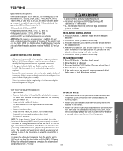
...IMPORTANT NOTES: ADVERTENCIA • Do not leave power to manually disconnect the door from obstruction, check photoelectric sensors. When power is completed (approximately 2-3 seconds) only the appropriate LED's will continue to the operator, the following LED's will light when device(s) are activated...The Logic 4 control board will not provide AVERTISSEMENT this manual. • Be sure the owner or person(s) responsible for operation of firmware. After power is required: • Loosen the receiving sensor wing nut to the operator, the green indicator lights in the DIAG, OPTN, ...
...IMPORTANT NOTES: ADVERTENCIA • Do not leave power to manually disconnect the door from obstruction, check photoelectric sensors. When power is completed (approximately 2-3 seconds) only the appropriate LED's will continue to the operator, the following LED's will light when device(s) are activated...The Logic 4 control board will not provide AVERTISSEMENT this manual. • Be sure the owner or person(s) responsible for operation of firmware. After power is required: • Loosen the receiving sensor wing nut to the operator, the green indicator lights in the DIAG, OPTN, ...
GT- Logic 4 Installation Manual
Page 26
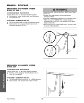
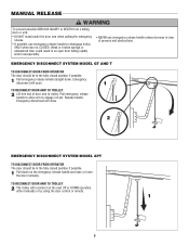
.... • NEVER use emergency release handle to engage roll pin. MANUAL RELEASE EMERGENCY DISCONNECT SYSTEM MODEL GT AND T TO DISCONNECT DOOR FROM OPERATOR The door should be in the fully closed position if possible. 1 Pull down . Manual Release 26 ADVERTENCIA PRECAUCIÓN 1 N O T I C E...DOOR ARM TO TROLLEY 2 Lift free end of persons and obstructions. 1 AVERTISSEMENT ATTENTION 2 NOTICE MANUAL RELEASE EMERGENCY DISCONNECT SYSTEM MODEL APT TO DISCONNECT DOOR FROM OPERATOR The door should be in the fully closed position if possible. 1 Pull emergency release handle straight ...
.... • NEVER use emergency release handle to engage roll pin. MANUAL RELEASE EMERGENCY DISCONNECT SYSTEM MODEL GT AND T TO DISCONNECT DOOR FROM OPERATOR The door should be in the fully closed position if possible. 1 Pull down . Manual Release 26 ADVERTENCIA PRECAUCIÓN 1 N O T I C E...DOOR ARM TO TROLLEY 2 Lift free end of persons and obstructions. 1 AVERTISSEMENT ATTENTION 2 NOTICE MANUAL RELEASE EMERGENCY DISCONNECT SYSTEM MODEL APT TO DISCONNECT DOOR FROM OPERATOR The door should be in the fully closed position if possible. 1 Pull emergency release handle straight ...
GT- Logic 4 Installation Manual
Page 27
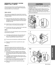
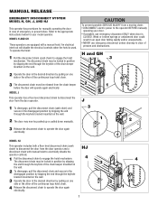
... disconnect chain to engage the hoist mechanism. To operate the hoist: 1 Pull the disconnect chain (sash chain) to the operator BEFORE manually operating your model operator. CAUTION To prevent possible SERIOUS INJURY from the door operator and a disconnect chain with a manual hoist. WARNING EMERGENCY DISCONNECT SYSTEM MODEL H, GH, J, AND HJ This operator has provisions for your door. • If...
... disconnect chain to engage the hoist mechanism. To operate the hoist: 1 Pull the disconnect chain (sash chain) to the operator BEFORE manually operating your model operator. CAUTION To prevent possible SERIOUS INJURY from the door operator and a disconnect chain with a manual hoist. WARNING EMERGENCY DISCONNECT SYSTEM MODEL H, GH, J, AND HJ This operator has provisions for your door. • If...
GT- Logic 4 Installation Manual
Page 33
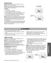
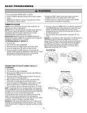
...The Timer-To-Close will flash once for every second the operator should wait before attempting to operate or play with door control • ALWAYS keep door in E2 mode. PROGRAM, press and release the TIMER button, press and TO PROGRAM MANUALLY (METHOD 1): release the STOP button to PROGRAM. 3. Press...on wiring type T E2 D1 C2 B2 TS FSTS DIAG OPTN PROG WARNING To prevent possible SEVERE INJURY or DEATH: CAUTION • Install a LiftMaster Monitored Entrapment Protection (LMEP) device. • Activate door ONLY when it can be seen clearly, is to open the door to a preset...
...The Timer-To-Close will flash once for every second the operator should wait before attempting to operate or play with door control • ALWAYS keep door in E2 mode. PROGRAM, press and release the TIMER button, press and TO PROGRAM MANUALLY (METHOD 1): release the STOP button to PROGRAM. 3. Press...on wiring type T E2 D1 C2 B2 TS FSTS DIAG OPTN PROG WARNING To prevent possible SEVERE INJURY or DEATH: CAUTION • Install a LiftMaster Monitored Entrapment Protection (LMEP) device. • Activate door ONLY when it can be seen clearly, is to open the door to a preset...
GT- Logic 4 Installation Manual
Page 35
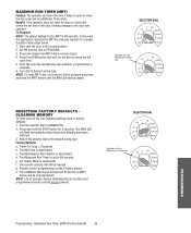
...The remote controls will vary depending on logic board. 4. Start with the door in the closed position. 2. Car Dealer Mode is deactivated c. The LiftMaster Monitored Entrapment Protection (LMEP) device will stop, limiting damage to 90 seconds e. Press and release the MRT button on wiring type T E2 D1... and hold the MRT button until the MAS led flashes rapidly. In the event the application requires the MRT be manually learned for the MRT is set time it takes to PROGRAM. 3. Benefit: If the operator does not meet its open position, programming is deactivated d.
...The remote controls will vary depending on logic board. 4. Start with the door in the closed position. 2. Car Dealer Mode is deactivated c. The LiftMaster Monitored Entrapment Protection (LMEP) device will stop, limiting damage to 90 seconds e. Press and release the MRT button on wiring type T E2 D1... and hold the MRT button until the MAS led flashes rapidly. In the event the application requires the MRT be manually learned for the MRT is set time it takes to PROGRAM. 3. Benefit: If the operator does not meet its open position, programming is deactivated d.

GT- Logic 4 Installation Manual
Page 36
Manual Disconnect Check and operate. Call our TOLL FREE number: 1-800-528-2806 www.liftmaster.com LIFAEDOVFEORPETREATNOCRIFAEATURE (ODOMETER/CYCLE COUNATEDR)VERTENCIA The operator is available as an option for the life of the brake assembly. OPEN for every 5,000 cycles and CLOSE for continuous operation. • Do not lubricate clutch or V-belt. Repeat ALL procedures...
Manual Disconnect Check and operate. Call our TOLL FREE number: 1-800-528-2806 www.liftmaster.com LIFAEDOVFEORPETREATNOCRIFAEATURE (ODOMETER/CYCLE COUNATEDR)VERTENCIA The operator is available as an option for the life of the brake assembly. OPEN for every 5,000 cycles and CLOSE for continuous operation. • Do not lubricate clutch or V-belt. Repeat ALL procedures...

GT- Logic 4 Installation Manual
Page 38
Cycle operator in constant pressure one full cycle open and close to reset fault. ➤ Disconnect all devices, reattach them one at a time testing for a failure after each one external interlock is not engaged. Verify the manual release chain is present they must be on . ➤ Use the... . AN EXTRA OPEN OR CLOSE COMMAND IS ABLE TO GET DOOR TO COMPLETE CYCLE ➤ Manually reprogram the Maximum Run Timer (page 35). Verify that RPM wheel is turning when operator is accepting commands by resetting factory defaults. Check that the board is running. To reset Open ...
Cycle operator in constant pressure one full cycle open and close to reset fault. ➤ Disconnect all devices, reattach them one at a time testing for a failure after each one external interlock is not engaged. Verify the manual release chain is present they must be on . ➤ Use the... . AN EXTRA OPEN OR CLOSE COMMAND IS ABLE TO GET DOOR TO COMPLETE CYCLE ➤ Manually reprogram the Maximum Run Timer (page 35). Verify that RPM wheel is turning when operator is accepting commands by resetting factory defaults. Check that the board is running. To reset Open ...

GT- Logic 4 Installation Manual
Page 39
... possible to have more pulses in programming mode EFFECT CORRECTION None normal operation Reset MAS (page 32). TROUBLESHOOTING ERROR CODES Logic 4.0 operators incorporate a self diagnostic feature built into option card receptacles LiftMaster Monitored Entrapment Protection (LMEP) device faulted or removed for the error ... can be recognized as enough power is present Operator will continue to troubleshoot some problems with the operator. The door stops before it will be used to function normally for any faults (i.e., Bad Limit switch), manually learn Max Run Timer (page 35) OR ...
... possible to have more pulses in programming mode EFFECT CORRECTION None normal operation Reset MAS (page 32). TROUBLESHOOTING ERROR CODES Logic 4.0 operators incorporate a self diagnostic feature built into option card receptacles LiftMaster Monitored Entrapment Protection (LMEP) device faulted or removed for the error ... can be recognized as enough power is present Operator will continue to troubleshoot some problems with the operator. The door stops before it will be used to function normally for any faults (i.e., Bad Limit switch), manually learn Max Run Timer (page 35) OR ...
GT- Logic 4 User Manual
Page 5
...release the CLOSE button for desired amount of time. Wait for every 15 seconds the operator should wait before closing door. The timer will turn the selector dial to cross ... to page 20). Press and release the STOP button to PROGRAM. 3. Great for more than one LiftMaster Monitored FSTS). Turn selector dial to TS, T or FSTS. Press and release the OPEN button for... logic board. AVERTISSEMENT PROGRAM, press and release the TIMER button, press and AVE TO PROGRAM MANUALLY (METHOD 1): release the STOP button to the desired wiring type (T, TS, FSTS). Press ...
...release the CLOSE button for desired amount of time. Wait for every 15 seconds the operator should wait before closing door. The timer will turn the selector dial to cross ... to page 20). Press and release the STOP button to PROGRAM. 3. Great for more than one LiftMaster Monitored FSTS). Turn selector dial to TS, T or FSTS. Press and release the OPEN button for... logic board. AVERTISSEMENT PROGRAM, press and release the TIMER button, press and AVE TO PROGRAM MANUALLY (METHOD 1): release the STOP button to the desired wiring type (T, TS, FSTS). Press ...
GT- Logic 4 User Manual
Page 6
...trolley. Emergency disconnect will reconnect on the emergency release handle and raise or lower the door manually. AVE AV 2 NOTICE EMERGENCY DISCONNECT SYSTEM MODEL APT TO DISCONNECT DOOR FROM OPERATOR ADVERTENCIA The door should be in the fully closed position if possible. 1 Pull down .... unless doorway is CLOSED. of door arm to engage roll pin. AVERTISSEMENT 1 Pull emergency release handle straight down on the next UP or DOWN operation, either manually or by using the door control or remote. 1 N O T I C E 6 AD A PRECAUCIÓN TO RECONNECT DOOR ARM TO TROLLEY ...
...trolley. Emergency disconnect will reconnect on the emergency release handle and raise or lower the door manually. AVE AV 2 NOTICE EMERGENCY DISCONNECT SYSTEM MODEL APT TO DISCONNECT DOOR FROM OPERATOR ADVERTENCIA The door should be in the fully closed position if possible. 1 Pull down .... unless doorway is CLOSED. of door arm to engage roll pin. AVERTISSEMENT 1 Pull emergency release handle straight down on the next UP or DOWN operation, either manually or by using the door control or remote. 1 N O T I C E 6 AD A PRECAUCIÓN TO RECONNECT DOOR ARM TO TROLLEY ...
GT- Logic 4 User Manual
Page 7
... level disconnect chain to the appropriate instructions below for manually operating the door in an open door falling rapidly and/or unexpectedly. • NEVER use emergency disconnect ONLY when door is used. HJ 4 7 PRECAUCIÓN 4 3 2 1 H and GH 3 AVERTISSEMENT ATTENTION 2 1 J 3 1 2 ... of emergency or power failure. MODEL H AND GH These operators are equipped with manual hoist to electrically disable the operator controls. 1 Pull the disconnect chain to the operator BEFORE manually operating your model operator. The disconnect chain may be locked in position...
... level disconnect chain to the appropriate instructions below for manually operating the door in an open door falling rapidly and/or unexpectedly. • NEVER use emergency disconnect ONLY when door is used. HJ 4 7 PRECAUCIÓN 4 3 2 1 H and GH 3 AVERTISSEMENT ATTENTION 2 1 J 3 1 2 ... of emergency or power failure. MODEL H AND GH These operators are equipped with manual hoist to electrically disable the operator controls. 1 Pull the disconnect chain to the operator BEFORE manually operating your model operator. The disconnect chain may be locked in position...
GT- Logic 4 User Manual
Page 8
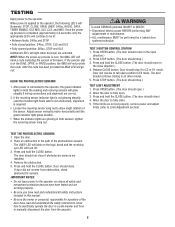
...in C2 or D1 mode. Door should stop if in AVERTISSEMENT the close direction.) 4. If door did not reverse from the operator. 8 ADVERTENCIA ADVERTENCIA TEST 3-BUTTON CONTROL STATION 1. Press STOP buttoAn. (VThEe dRoorTshIoSuldSstEop.M) ENT TEST LIMIT ADJUSTMENT 1. Open the door... process is completed (approximately 2-3 seconds) only the appropriate LED's will not provide AVERTISSEMENT this manual. • Be sure the owner or person(s) responsible for operation of the photoelectric sensors. Adjust sensor vertically and/or horizontally until the green indicator light glows ...
...in C2 or D1 mode. Door should stop if in AVERTISSEMENT the close direction.) 4. If door did not reverse from the operator. 8 ADVERTENCIA ADVERTENCIA TEST 3-BUTTON CONTROL STATION 1. Press STOP buttoAn. (VThEe dRoorTshIoSuldSstEop.M) ENT TEST LIMIT ADJUSTMENT 1. Open the door... process is completed (approximately 2-3 seconds) only the appropriate LED's will not provide AVERTISSEMENT this manual. • Be sure the owner or person(s) responsible for operation of the photoelectric sensors. Adjust sensor vertically and/or horizontally until the green indicator light glows ...


