Service Manual
Page 8
... removal and replacement 4-99 Connector locations 5-1 Locations 5-1 Printer boards 5-1 Printer motors 5-2 Printer sensors 5-3 Cartridge contact assembly pin locations (cyan, magenta and yellow 5-4 Cartridge contact assembly pin locations (black 5-5 System board cabling reference 5-6 Connectors 5-7 System board 5-7 Autoconnect-top 5-18 Autoconnect-bottom 5-19 Transfer high voltage power supply (HVPS 5-20 Developer high voltage power supply (HVPS) board...
... removal and replacement 4-99 Connector locations 5-1 Locations 5-1 Printer boards 5-1 Printer motors 5-2 Printer sensors 5-3 Cartridge contact assembly pin locations (cyan, magenta and yellow 5-4 Cartridge contact assembly pin locations (black 5-5 System board cabling reference 5-6 Connectors 5-7 System board 5-7 Autoconnect-top 5-18 Autoconnect-bottom 5-19 Transfer high voltage power supply (HVPS 5-20 Developer high voltage power supply (HVPS) board...
Service Manual
Page 9
5061 Low voltage power supply (LVPS 5-23 LVPS cable connectors to system board 5-23 LVPS fuser connectors 5-24 Media size sensing board 5-25 High-capacity input tray (HCIT 5-26 StapleSmart finisher 5-28 Preventive maintenance 6-1 Safety inspection guide 6-1 Scheduled maintenance 6-1 Standard fusers 6-1 ITU Maintenance kits 6-1 Lubrication specifications 6-2 Lubrication for replacement motors 6-2 Fuser drive assembly 6-2 Cartridge...
5061 Low voltage power supply (LVPS 5-23 LVPS cable connectors to system board 5-23 LVPS fuser connectors 5-24 Media size sensing board 5-25 High-capacity input tray (HCIT 5-26 StapleSmart finisher 5-28 Preventive maintenance 6-1 Safety inspection guide 6-1 Scheduled maintenance 6-1 Standard fusers 6-1 ITU Maintenance kits 6-1 Lubrication specifications 6-2 Lubrication for replacement motors 6-2 Fuser drive assembly 6-2 Cartridge...
Service Manual
Page 41
... Data Out Electrophotographic Process Erasable Programmable Read-Only Memory Electrostatic Discharge Field Replaceable Unit Gigabyte High-Capacity Input Tray High-Capacity Output Finisher High Voltage Power Supply Image Transfer Unit Black Light Amplification by Stimulated Emission of Radiation Liquid ...Crystal Display Light-Emitting Diode Low Voltage Power Supply Magenta Masked Read Only Memory Microswitch Nonvolatile Random Access Memory Original Equipment Manufacturer Optical Sensor Photoconductor Picture element Power-On Reset Power-On Self Test Position Sensing Device Pulse Width ...
... Data Out Electrophotographic Process Erasable Programmable Read-Only Memory Electrostatic Discharge Field Replaceable Unit Gigabyte High-Capacity Input Tray High-Capacity Output Finisher High Voltage Power Supply Image Transfer Unit Black Light Amplification by Stimulated Emission of Radiation Liquid ...Crystal Display Light-Emitting Diode Low Voltage Power Supply Magenta Masked Read Only Memory Microswitch Nonvolatile Random Access Memory Original Equipment Manufacturer Optical Sensor Photoconductor Picture element Power-On Reset Power-On Self Test Position Sensing Device Pulse Width ...
Service Manual
Page 54
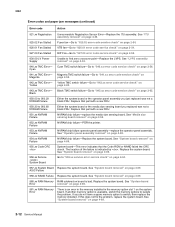
... failure is available, switch the memory options to find zero crossover point-Replace the LVPS. See "System board removal" on page 2-55. 930.09 LV Power Supply Unable to isolate the problem. If this does not fix the problem, replace the system board. See "ITU assembly removal" on page 4-49. ...page 4-58. 952.xx NVRAM Failure NVRAM chip failure-POR the printer. 953.xx NVRAM Failure NVRAM chip failure operator panel assembly-replace the operator panel assembly. Replace that the Code ROM or NAND failed the CRC check. See "Media size sensing board removal" on page 4-53. 940.xx ...
... failure is available, switch the memory options to find zero crossover point-Replace the LVPS. See "System board removal" on page 2-55. 930.09 LV Power Supply Unable to isolate the problem. If this does not fix the problem, replace the system board. See "ITU assembly removal" on page 4-49. ...page 4-58. 952.xx NVRAM Failure NVRAM chip failure-POR the printer. 953.xx NVRAM Failure NVRAM chip failure operator panel assembly-replace the operator panel assembly. Replace that the Code ROM or NAND failed the CRC check. See "Media size sensing board removal" on page 4-53. 940.xx ...
Service Manual
Page 99
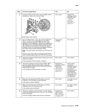
... tightened down . See "Cartridge contact assembly removal" on page 4-39. Note: You may need to turn the printer off to step 3 No Replace the cartridge contact assembly. Is the developer HVPS cracked or broken? 5 Check the mounting of the developer HVPS. See "System board removal" on ... the power supply are tightened down and the board is still displayed. Is the cable properly installed? 8 Check the voltage at J6 on the system board. Correctly connect the cable. Recheck the printer to see if a 940 Error is positioned and mounted correctly. Go to step 8 Replace the ...
... tightened down . See "Cartridge contact assembly removal" on page 4-39. Note: You may need to turn the printer off to step 3 No Replace the cartridge contact assembly. Is the developer HVPS cracked or broken? 5 Check the mounting of the developer HVPS. See "System board removal" on ... the power supply are tightened down and the board is still displayed. Is the cable properly installed? 8 Check the voltage at J6 on the system board. Correctly connect the cable. Recheck the printer to see if a 940 Error is positioned and mounted correctly. Go to step 8 Replace the ...
Service Manual
Page 101
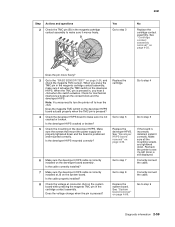
...the TMC pin is positioned and mounted correctly. Is the developer HVPS cracked or broken? 5 Check the mounting of the developer HVPS. Replace the cartridge. Correctly connect the cable. Is the cable correctly installed? 7 Make sure the developer HVPS cable is correctly installed at connector...power supply are tightened down and the board is pressed in, you press the TMC pin in the magenta cartridge contact assembly, make sure it is correctly installed on the system board while pressing the magenta TMC pin in the cartridge contact assembly. Go to step 3 No Replace...
...the TMC pin is positioned and mounted correctly. Is the developer HVPS cracked or broken? 5 Check the mounting of the developer HVPS. Replace the cartridge. Correctly connect the cable. Is the cable correctly installed? 7 Make sure the developer HVPS cable is correctly installed at connector...power supply are tightened down and the board is pressed in, you press the TMC pin in the magenta cartridge contact assembly, make sure it is correctly installed on the system board while pressing the magenta TMC pin in the cartridge contact assembly. Go to step 3 No Replace...

Service Manual
Page 103
...on page 4-39. Replace the cartridge. Go to step 6 Replace the developer HVPS assembly. Is the developer HVPS cracked or broken? 5 Check the mounting of the developer HVPS. Go to step 9 Diagnostic information 2-61 Make sure the screws that mount the power supply are tightened down and... the board is correctly installed at connector J6-16 on the developer HVPS. Go to step 4 Go to step 3 No Replace the cartridge contact assembly. Check for mechanical interference between the...
...on page 4-39. Replace the cartridge. Go to step 6 Replace the developer HVPS assembly. Is the developer HVPS cracked or broken? 5 Check the mounting of the developer HVPS. Go to step 9 Diagnostic information 2-61 Make sure the screws that mount the power supply are tightened down and... the board is correctly installed at connector J6-16 on the developer HVPS. Go to step 4 Go to step 3 No Replace the cartridge contact assembly. Check for mechanical interference between the...
Service Manual
Page 105
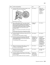
...may need to turn the printer off to step 3 No Replace the cartridge contact assembly. Make sure all the mounting screws are properly tightened down . Correctly install the cable. Make sure the screws that mount the power supply are tightened down and the board is positioned and mounted correctly....on the developer HVPS. Is the developer HVPS mounted correctly? 6 Make sure the developer HVPS cable is still displayed. Go to step 6 Replace the developer HVPS assembly. 5061 Step 2 Actions and questions Check the TMC pin (B) in the black cartridge contact assembly to make sure it...
...may need to turn the printer off to step 3 No Replace the cartridge contact assembly. Make sure all the mounting screws are properly tightened down . Correctly install the cable. Make sure the screws that mount the power supply are tightened down and the board is positioned and mounted correctly....on the developer HVPS. Is the developer HVPS mounted correctly? 6 Make sure the developer HVPS cable is still displayed. Go to step 6 Replace the developer HVPS assembly. 5061 Step 2 Actions and questions Check the TMC pin (B) in the black cartridge contact assembly to make sure it...
Service Manual
Page 116
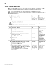
...voltage correct? 5 Low voltage power supply-Turn the power off , the LCD display is turned on. See "LVPS assembly removal" on ? No Go to the proper power setting for the geographic area you are in. AC power service check The printer appears to see if the Power on LED on the system ... check" on , and no motors turn the printer on, and check to be installed. Replace the LVPS assembly. Is the AC line voltage correct? 3 AC power cord Is the power cord in poor condition, replace the cord. Turn the machine on J18-3 and J18-4. The voltage should measure approximately +5 V dc....
...voltage correct? 5 Low voltage power supply-Turn the power off , the LCD display is turned on. See "LVPS assembly removal" on ? No Go to the proper power setting for the geographic area you are in. AC power service check The printer appears to see if the Power on LED on the system ... check" on , and no motors turn the printer on, and check to be installed. Replace the LVPS assembly. Is the AC line voltage correct? 3 AC power cord Is the power cord in poor condition, replace the cord. Turn the machine on J18-3 and J18-4. The voltage should measure approximately +5 V dc....

Service Manual
Page 151
...5061 Quality troubleshooting (continued) Symptom Cause Solution Blank pages The print cartridges are defective. • Your printer requires servicing. • Replace the print cartridges. • Call for service. Contact your next level of support. Solid color pages • The print cartridges are... you should be replaced when 83 ITU Maintenance appears. Step 1 2 3 Actions and questions Second transfer roll assembly-Check the second transfer roll for damage, toner, or foreign material. The paper curls badly once it . Transfer high voltage power supply, HV wiring, ...
...5061 Quality troubleshooting (continued) Symptom Cause Solution Blank pages The print cartridges are defective. • Your printer requires servicing. • Replace the print cartridges. • Call for service. Contact your next level of support. Solid color pages • The print cartridges are... you should be replaced when 83 ITU Maintenance appears. Step 1 2 3 Actions and questions Second transfer roll assembly-Check the second transfer roll for damage, toner, or foreign material. The paper curls badly once it . Transfer high voltage power supply, HV wiring, ...
Service Manual
Page 183
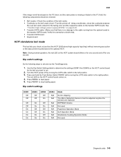
... Self Operation Mode Standalone Feeding Operation Mode Not used Diagnostic aids 3-5 Dip switch settings Do the following components should be adjusted anytime the sensors are replaced. Note: During normal operation, the red LED on the HCIT system board blinks on for shipping The Mirror Reflection Sensors must be checked: •... board HCIT standalone test mode This test lets you want to the transfer HVPS board. Press PBSW1 to feed paper. 5. See "Transfer high voltage power supply (HVPS)" on page 5-20. • Transfer HVPS cable-Make sure that there is missing or faded on . 4.
... Self Operation Mode Standalone Feeding Operation Mode Not used Diagnostic aids 3-5 Dip switch settings Do the following components should be adjusted anytime the sensors are replaced. Note: During normal operation, the red LED on the HCIT system board blinks on for shipping The Mirror Reflection Sensors must be checked: •... board HCIT standalone test mode This test lets you want to the transfer HVPS board. Press PBSW1 to feed paper. 5. See "Transfer high voltage power supply (HVPS)" on page 5-20. • Transfer HVPS cable-Make sure that there is missing or faded on . 4.
Service Manual
Page 363
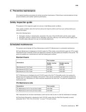
...or altered covers, especially in the area of the top cover and the power supply cover • Possible safety exposure from any unsafe conditions exist, find out how serious the hazard could be replaced to maintain the print quality and reliability of this inspection guide is to ...Oiler Nearly Exhausted is displayed at the same time. Both should be replaced to aid you correct the hazard. Preventive maintenance 6-1 Safety inspection guide The purpose of the printer. If any non-Lexmark attachments Scheduled maintenance The operator panel displays 80 Fuser Maintenance and 83 ...
...or altered covers, especially in the area of the top cover and the power supply cover • Possible safety exposure from any unsafe conditions exist, find out how serious the hazard could be replaced to maintain the print quality and reliability of this inspection guide is to ...Oiler Nearly Exhausted is displayed at the same time. Both should be replaced to aid you correct the hazard. Preventive maintenance 6-1 Safety inspection guide The purpose of the printer. If any non-Lexmark attachments Scheduled maintenance The operator panel displays 80 Fuser Maintenance and 83 ...
Service Manual
Page 455
... On Disk 3-35 L LCD Brightness 2-123 LCD Contrast 2-123 LCD Test 3-15 low voltage power supply (LVPS) connections 5-23, 5-24 location 5-1 parts catalog 7-31 removal 4-53 service check 2-55 lubrication cartridge drive assembly replacement 6-3 fuser drive assembly replacement 6-2 ITU drive assembly replacement 6-3 lubrication specifications 6-2 M maintenance kits ITU Maintenance kits 6-1 standard fusers 6-1 maintenance, scheduled 6-1 Manual Color...
... On Disk 3-35 L LCD Brightness 2-123 LCD Contrast 2-123 LCD Test 3-15 low voltage power supply (LVPS) connections 5-23, 5-24 location 5-1 parts catalog 7-31 removal 4-53 service check 2-55 lubrication cartridge drive assembly replacement 6-3 fuser drive assembly replacement 6-2 ITU drive assembly replacement 6-3 lubrication specifications 6-2 M maintenance kits ITU Maintenance kits 6-1 standard fusers 6-1 maintenance, scheduled 6-1 Manual Color...


