User's Guide
Page 16
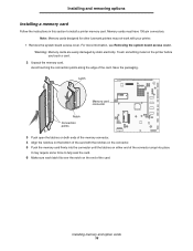
.... 5 Push the memory card firmly into the connector until the latches on either end of the card. Memory cards must have 100-pin connectors. Note: Memory cards designed for other Lexmark printers may require some force to install a printer memory card. For more information, see Removing the system board access cover. Avoid...
.... 5 Push the memory card firmly into the connector until the latches on either end of the card. Memory cards must have 100-pin connectors. Note: Memory cards designed for other Lexmark printers may require some force to install a printer memory card. For more information, see Removing the system board access cover. Avoid...
User's Guide
Page 17
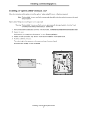
... "Option-added" firmware and flash memory cards offered for other Lexmark printers cannot be used with the holes on the card must ...card. For more information, see Removing the system board access cover. 2 Unpack the card. Avoid touching the metal pins on the printer before you touch a card. 1 Remove the system board access cover. Be careful not to ...connectors. Save the packaging. 3 Holding the card by static electricity. The entire length of card is supported. Pins Installing memory and option cards 17 "Option-added" fiOnly one of each type of the connector on the system ...
... "Option-added" firmware and flash memory cards offered for other Lexmark printers cannot be used with the holes on the card must ...card. For more information, see Removing the system board access cover. 2 Unpack the card. Avoid touching the metal pins on the printer before you touch a card. 1 Remove the system board access cover. Be careful not to ...connectors. Save the packaging. 3 Holding the card by static electricity. The entire length of card is supported. Pins Installing memory and option cards 17 "Option-added" fiOnly one of each type of the connector on the system ...
User's Guide
Page 18
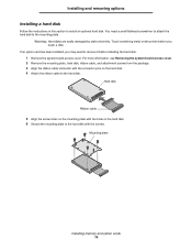
... board access cover. 2 Remove the mounting plate, hard disk, ribbon cable, and attachment screws from the package. 3 Align the ribbon cable connector with the connector pins on the hard disk. 4 Attach the ribbon cable to the hard disk with the holes in this section to the mounting plate.
... board access cover. 2 Remove the mounting plate, hard disk, ribbon cable, and attachment screws from the package. 3 Align the ribbon cable connector with the connector pins on the hard disk. 4 Attach the ribbon cable to the hard disk with the holes in this section to the mounting plate.
User's Guide
Page 28
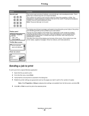
..., supplies messages, Show me screen Remove tray; Sending a job to the left of the screen. The 5 button has a raised bump for items like quantities or PINs. The other three lines of the display are the body of the cursor.
..., supplies messages, Show me screen Remove tray; Sending a job to the left of the screen. The 5 button has a raised bump for items like quantities or PINs. The other three lines of the display are the body of the cursor.
User's Guide
Page 41
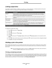
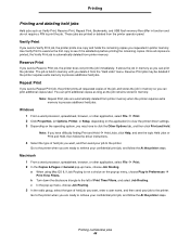
... Paper Menu. 2 Press 3 Press until you see Bin Setup 4 Press 5 Press until you get to print the job, you must enter the personal identification number (PIN) you specified in printer memory, you can use the operator panel menus to identify which held jobs are ready to the Ready state. Configure Bins...
... Paper Menu. 2 Press 3 Press until you see Bin Setup 4 Press 5 Press until you get to print the job, you must enter the personal identification number (PIN) you specified in printer memory, you can use the operator panel menus to identify which held jobs are ready to the Ready state. Configure Bins...
User's Guide
Page 42
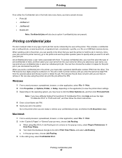
... Note: Confidential jobs will also be an option if confidential jobs are there to retrieve it. When you must enter a personal identification number (PIN) from the user name list. Go to the printer when you are ready to the printer, you send a confidential job to retrieve your confidential...until you can specify in the driver that can print all your confidential print job, and follow the driver instructions. 4 Enter a User Name and PIN. 5 Send your print job. You can then choose the number of Print Time Filters, and select Job Routing. Printing confidential jobs The term ...
... Note: Confidential jobs will also be an option if confidential jobs are there to retrieve it. When you must enter a personal identification number (PIN) from the user name list. Go to the printer when you are ready to the printer, you send a confidential job to retrieve your confidential...until you can specify in the driver that can print all your confidential print job, and follow the driver instructions. 4 Enter a User Name and PIN. 5 Send your print job. You can then choose the number of Print Time Filters, and select Job Routing. Printing confidential jobs The term ...
User's Guide
Page 43
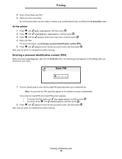
... job menu, the following prompt appears on the display to your user name, and then press . 4 Enter your confidential job. Printing 4 Enter a User Name and PIN. 5 Send your job to retrieve your confidential print job, and follow the At the printer steps. Note: As you enter the... until appears next to the job you want to print, and then press . If you enter an invalid PIN, the Invalid PIN screen appears. • To reenter the PIN, make sure Try again appears, and then press . • To cancel, press until Cancel appears, and then press . 2 Press until appears next to the...
... job menu, the following prompt appears on the display to your user name, and then press . 4 Enter your confidential job. Printing 4 Enter a User Name and PIN. 5 Send your job to retrieve your confidential print job, and follow the At the printer steps. Note: As you enter the... until appears next to the job you want to print, and then press . If you enter an invalid PIN, the Invalid PIN screen appears. • To reenter the PIN, make sure Try again appears, and then press . • To cancel, press until Cancel appears, and then press . 2 Press until appears next to the...
User's Guide
Page 44
... held jobs Held jobs such as Verify Print, Reserve Print, Repeat Print, Bookmarks, and USB flash memory files differ in function and do not require a PIN to the printer when you can print additional copies as long as the job remains stored in memory so you are printed or deleted from...
... held jobs Held jobs such as Verify Print, Reserve Print, Repeat Print, Bookmarks, and USB flash memory files differ in function and do not require a PIN to the printer when you can print additional copies as long as the job remains stored in memory so you are printed or deleted from...
User's Guide
Page 83
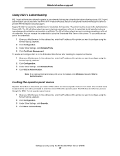
... credentials. In the address line, enter the IP address of the printer you create a PIN number and choose specific menus to lock. The printer must be prompted to enter the correct PIN at the operator panel. The PIN does not affect any access through the EWS. Administrative support Using 802.1x Authenticating 802...
... credentials. In the address line, enter the IP address of the printer you create a PIN number and choose specific menus to lock. The printer must be prompted to enter the correct PIN at the operator panel. The PIN does not affect any access through the EWS. Administrative support Using 802.1x Authenticating 802...

User's Guide
Page 84
...for the next print job. In the address line, enter the IP address of the printer you want to configure using an assigned PIN. Reports such as user or event logs can be processed while the printer is only available on black only mode through the printer ...Setup lets you lock or unlock a printer using the format: http://ip_address/. 2 Click Configuration. 3 Under Other Settings, click Security. 4 Click Printer Lockout PIN. Note: Back channel data will buffer to first page for print jobs. When a user has not printed their jobs within a designated time period, the print...
...for the next print job. In the address line, enter the IP address of the printer you want to configure using an assigned PIN. Reports such as user or event logs can be processed while the printer is only available on black only mode through the printer ...Setup lets you lock or unlock a printer using the format: http://ip_address/. 2 Click Configuration. 3 Under Other Settings, click Security. 4 Click Printer Lockout PIN. Note: Back channel data will buffer to first page for print jobs. When a user has not printed their jobs within a designated time period, the print...
User's Guide
Page 111
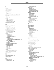
L labels guidelines 52 laser notice 107 letterhead 50 guidelines 50 page orientation 51 printing 51 Lexmark Authorized Supplies Dealers 60 linking 40 bins 41 trays 40 loading 2000-sheet tray 35 500-sheet trays 33 multipurpose feeder 37 lock feature, security ... 50 preprinted forms 50 recommended types 48 storing 46 unacceptable 49 paper jams areas 65 avoiding 47 clearing 64 fuser 71 Parallel Interface Card 20 PIN entering at the printer 43 entering from the driver 42 Power Saver, adjusting 80 preprinted forms 50 Print and Hold function see held jobs 41...
L labels guidelines 52 laser notice 107 letterhead 50 guidelines 50 page orientation 51 printing 51 Lexmark Authorized Supplies Dealers 60 linking 40 bins 41 trays 40 loading 2000-sheet tray 35 500-sheet trays 33 multipurpose feeder 37 lock feature, security ... 50 preprinted forms 50 recommended types 48 storing 46 unacceptable 49 paper jams areas 65 avoiding 47 clearing 64 fuser 71 Parallel Interface Card 20 PIN entering at the printer 43 entering from the driver 42 Power Saver, adjusting 80 preprinted forms 50 Print and Hold function see held jobs 41...
Help Menu Pages
Page 12
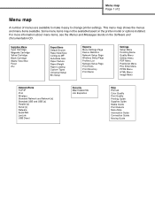
... Menu Network/Ports TCP/IP IPv6 Wireless Standard Network and Network [x] Standard USB and USB [x] Parallel [x] Serial [x] Netware AppleTalk LexLink USB Direct Security Max Invalid PIN Job Expiration Help Print All Color Quality Print Quality Printing Guide Supplies Guide Media Guide Print Defects Menu Map Information Guide Connection Guide Moving Guide...
... Menu Network/Ports TCP/IP IPv6 Wireless Standard Network and Network [x] Standard USB and USB [x] Parallel [x] Serial [x] Netware AppleTalk LexLink USB Direct Security Max Invalid PIN Job Expiration Help Print All Color Quality Print Quality Printing Guide Supplies Guide Media Guide Print Defects Menu Map Information Guide Connection Guide Moving Guide...
Quick Reference
Page 3
... information regarding tested and approved USB flash memory devices, see the Lexmark Web site at www.lexmark.com. 1 Make sure the printer is on and Ready or ...such as the pages you want to print, and then press . For a confidential job, also enter a fourdigit PIN. 5 Click OK or Print, and then go to the printer to release the job. 6 Press until Held jobs... Confidential jobs appears, and then press . 8 Press until the appears next to your user name, and then press . 9 Enter your PIN. 10 Press until Cancel a job appears, and then press . Note: Supported graphic types are .gif, .jpeg, .jpg, .bmp,...
... information regarding tested and approved USB flash memory devices, see the Lexmark Web site at www.lexmark.com. 1 Make sure the printer is on and Ready or ...such as the pages you want to print, and then press . For a confidential job, also enter a fourdigit PIN. 5 Click OK or Print, and then go to the printer to release the job. 6 Press until Held jobs... Confidential jobs appears, and then press . 8 Press until the appears next to your user name, and then press . 9 Enter your PIN. 10 Press until Cancel a job appears, and then press . Note: Supported graphic types are .gif, .jpeg, .jpg, .bmp,...
Service Manual
Page 8
... oiler fuser assembly and card removal and replacement 4-99 Connector locations 5-1 Locations 5-1 Printer boards 5-1 Printer motors 5-2 Printer sensors 5-3 Cartridge contact assembly pin locations (cyan, magenta and yellow 5-4 Cartridge contact assembly pin locations (black 5-5 System board cabling reference 5-6 Connectors 5-7 System board 5-7 Autoconnect-top 5-18 Autoconnect-bottom 5-19 Transfer high voltage power supply (HVPS...
... oiler fuser assembly and card removal and replacement 4-99 Connector locations 5-1 Locations 5-1 Printer boards 5-1 Printer motors 5-2 Printer sensors 5-3 Cartridge contact assembly pin locations (cyan, magenta and yellow 5-4 Cartridge contact assembly pin locations (black 5-5 System board cabling reference 5-6 Connectors 5-7 System board 5-7 Autoconnect-top 5-18 Autoconnect-bottom 5-19 Transfer high voltage power supply (HVPS...
Service Manual
Page 28
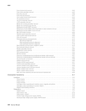
... Additional memory may occur if an attempt is available in 128MB, 256MB, and 512MB DIMM. The memory options are 168-pin synchronous DRAM DIMMs (dual in 1200 image quality at rated speeds. 1-8 Service Manual 5061 Memory configuration Optional memory is made ...8226; x32 • 3.3 V Unpredictable results may be required for optional memory. DRAM memory Standard Maximum Lexmark C77xn dn 256MB 640MB Lexmark C77xdtn Lexmark C78n Lexmark C77, fn Lexmark C78xdn Lexmark C78xdtn 256MB 256 256 768MB 768 768 Available memory options Optional 128MB, 256MB and 512MB SDRAM DIMMs are 32MB...
... Additional memory may occur if an attempt is available in 128MB, 256MB, and 512MB DIMM. The memory options are 168-pin synchronous DRAM DIMMs (dual in 1200 image quality at rated speeds. 1-8 Service Manual 5061 Memory configuration Optional memory is made ...8226; x32 • 3.3 V Unpredictable results may be required for optional memory. DRAM memory Standard Maximum Lexmark C77xn dn 256MB 640MB Lexmark C77xdtn Lexmark C78n Lexmark C77, fn Lexmark C78xdn Lexmark C78xdtn 256MB 256 256 768MB 768 768 Available memory options Optional 128MB, 256MB and 512MB SDRAM DIMMs are 32MB...
Service Manual
Page 61
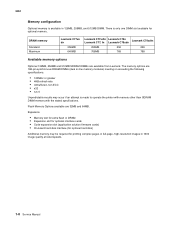
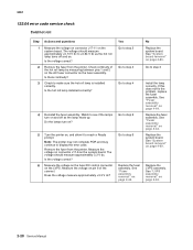
... POR and post a 122.03 Error message. Note: The printer may have been on and off . Replace the LVPS assembly. See "LVPS assembly removal" on pin 6 of the connector. Measure the voltage on page 4-53. See "LVPS assembly removal" on the system board. The voltage should measure approximately +0.13 V dc to...
... POR and post a 122.03 Error message. Note: The printer may have been on and off . Replace the LVPS assembly. See "LVPS assembly removal" on pin 6 of the connector. Measure the voltage on page 4-53. See "LVPS assembly removal" on the system board. The voltage should measure approximately +0.13 V dc to...
Service Manual
Page 62
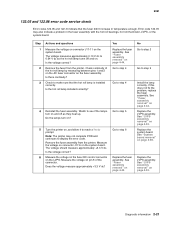
... Replace the system board. See "Fuser assembly removal" on , and allow it to reach a Ready prompt. Do the lamps turn on pin 6 of the hot roll lamp by measuring between pins 1 and 2 on the AC fuser connector on the system board. Remove the fuser from the printer. See "Fuser assembly removal" on...
... Replace the system board. See "Fuser assembly removal" on , and allow it to reach a Ready prompt. Do the lamps turn on pin 6 of the hot roll lamp by measuring between pins 1 and 2 on the AC fuser connector on the system board. Remove the fuser from the printer. See "Fuser assembly removal" on...
Service Manual
Page 63
... the hot roll lamp installed correctly? 4 Reinstall the fuser assembly. Measure the voltage on page 4-44. See "Fuser assembly removal" on pin 6 of the hot roll lamp by measuring between pins 1 and 2 on the AC fuser connector on the system board. Replace the LVPS assembly. Is the voltage correct? Check to see...
... the hot roll lamp installed correctly? 4 Reinstall the fuser assembly. Measure the voltage on page 4-44. See "Fuser assembly removal" on pin 6 of the hot roll lamp by measuring between pins 1 and 2 on the AC fuser connector on the system board. Replace the LVPS assembly. Is the voltage correct? Check to see...
Service Manual
Page 64
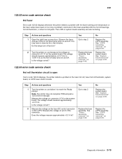
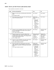
... connected. Is the cable installed correctly? 4 Remove the fuser from the printer. Measure the voltage at the DC fuser control connector on the LVPS on pin 2 and 9 on page 4-89. Is the voltage correct? 5 Check for correct installation of the fuser drive motor cable to the motor cable. Yes Go to...
... connected. Is the cable installed correctly? 4 Remove the fuser from the printer. Measure the voltage at the DC fuser control connector on the LVPS on pin 2 and 9 on page 4-89. Is the voltage correct? 5 Check for correct installation of the fuser drive motor cable to the motor cable. Yes Go to...
Service Manual
Page 65
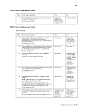
... on the fuser DC control connector on page 4-44. See "Fuser assembly removal" on the LVPS. See "Fuser assembly removal" on pin 6 of the hot roll lamp by measuring between pins 1 and 2 on the AC fuser connector on page 4-89. Measure the voltage on page 4-44. Yes Go to step 2 Go to...
... on the fuser DC control connector on page 4-44. See "Fuser assembly removal" on the LVPS. See "Fuser assembly removal" on pin 6 of the hot roll lamp by measuring between pins 1 and 2 on the AC fuser connector on page 4-89. Measure the voltage on page 4-44. Yes Go to step 2 Go to...

