Troubleshooting Guide
Page 1
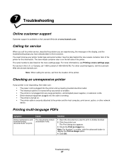
... do not print The printer is not responding, first make sure you have already taken to the Ready state. Lexmark™ C782 Troubleshooting Guide Online customer support Customer support is displayed. Calling for network printing. You need to know your printer is...Lexmark ABC. • If you are using a USB port, make sure: • The power cord is plugged into the printer and a properly grounded electrical outlet. • The electrical outlet is not turned off by any switch or breaker. • The printer is not plugged into any surge protectors, uninterrupted power supplies...
... do not print The printer is not responding, first make sure you have already taken to the Ready state. Lexmark™ C782 Troubleshooting Guide Online customer support Customer support is displayed. Calling for network printing. You need to know your printer is...Lexmark ABC. • If you are using a USB port, make sure: • The power cord is plugged into the printer and a properly grounded electrical outlet. • The electrical outlet is not turned off by any switch or breaker. • The printer is not plugged into any surge protectors, uninterrupted power supplies...
User's Guide
Page 7
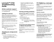
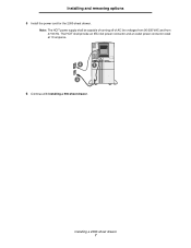
Installing a 2000-sheet drawer 7 Note: The HCIT power supply shall be capable of running off of AC line voltages from 90-256 VAC and from 47-63 Hz. The HCIT shall provide an IEC inlet power connector and an outlet power connector rated at 10 amperes. 2 1 3 6 Continue with Installing a 500-sheet drawer. Installing and removing options 5 Install the power cord for the 2000-sheet drawer.
Installing a 2000-sheet drawer 7 Note: The HCIT power supply shall be capable of running off of AC line voltages from 90-256 VAC and from 47-63 Hz. The HCIT shall provide an IEC inlet power connector and an outlet power connector rated at 10 amperes. 2 1 3 6 Continue with Installing a 500-sheet drawer. Installing and removing options 5 Install the power cord for the 2000-sheet drawer.
User's Guide
Page 87
...electrical outlet is not turned off by any switch or breaker. • The printer is not plugged into any surge protectors, uninterrupted power supplies, or extension cords. • Other electrical equipment plugged into the outlet is working. • The printer is turned on the ... is securely attached to the printer and the host computer, print server, option, or other countries/regions, visit the Lexmark Web site at www.lexmark.com. For other network device. Cause The documents contain unavailable fonts. 7 Troubleshooting Online customer support Customer support is available...
...electrical outlet is not turned off by any switch or breaker. • The printer is not plugged into any surge protectors, uninterrupted power supplies, or extension cords. • Other electrical equipment plugged into the outlet is working. • The printer is turned on the ... is securely attached to the printer and the host computer, print server, option, or other countries/regions, visit the Lexmark Web site at www.lexmark.com. For other network device. Cause The documents contain unavailable fonts. 7 Troubleshooting Online customer support Customer support is available...
User's Guide
Page 107
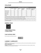
... China RoHS Part Name Hazardous Substances or Elements Lead (Pb) Mercury (Hg) Cadmium (Cd) Hexavalent Chromium (CrVI) Polybrominated Polybrominated biphenyl (PBB) diphenylether (PBDE) Circuit boards X O O O O O Power supply X O O O O O Metal shafts X O O O O O Metal rollers X O O O O O Motors X O O O O O O: Indicates that the content of the toxic and hazardous substance in at least one homogeneous material of certain hazardous substances...
... China RoHS Part Name Hazardous Substances or Elements Lead (Pb) Mercury (Hg) Cadmium (Cd) Hexavalent Chromium (CrVI) Polybrominated Polybrominated biphenyl (PBB) diphenylether (PBDE) Circuit boards X O O O O O Power supply X O O O O O Metal shafts X O O O O O Metal rollers X O O O O O Motors X O O O O O O: Indicates that the content of the toxic and hazardous substance in at least one homogeneous material of certain hazardous substances...
Service Manual
Page 8
..., magenta and yellow 5-4 Cartridge contact assembly pin locations (black 5-5 System board cabling reference 5-6 Connectors 5-7 System board 5-7 Autoconnect-top 5-18 Autoconnect-bottom 5-19 Transfer high voltage power supply (HVPS 5-20 Developer high voltage power supply (HVPS) board 5-22 viii Service Manual
..., magenta and yellow 5-4 Cartridge contact assembly pin locations (black 5-5 System board cabling reference 5-6 Connectors 5-7 System board 5-7 Autoconnect-top 5-18 Autoconnect-bottom 5-19 Transfer high voltage power supply (HVPS 5-20 Developer high voltage power supply (HVPS) board 5-22 viii Service Manual
Service Manual
Page 9
5061 Low voltage power supply (LVPS 5-23 LVPS cable connectors to system board 5-23 LVPS fuser connectors 5-24 Media size sensing board 5-25 High-capacity input tray (HCIT 5-26 StapleSmart ...
5061 Low voltage power supply (LVPS 5-23 LVPS cable connectors to system board 5-23 LVPS fuser connectors 5-24 Media size sensing board 5-25 High-capacity input tray (HCIT 5-26 StapleSmart ...
Service Manual
Page 41
...-Capacity Input Tray High-Capacity Output Finisher High Voltage Power Supply Image Transfer Unit Black Light Amplification by Stimulated Emission of Radiation Liquid Crystal Display Light-Emitting Diode Low Voltage Power Supply Magenta Masked Read Only Memory Microswitch Nonvolatile Random Access... Memory Original Equipment Manufacturer Optical Sensor Photoconductor Picture element Power-On Reset Power-On Self Test Position Sensing Device Pulse Width ...
...-Capacity Input Tray High-Capacity Output Finisher High Voltage Power Supply Image Transfer Unit Black Light Amplification by Stimulated Emission of Radiation Liquid Crystal Display Light-Emitting Diode Low Voltage Power Supply Magenta Masked Read Only Memory Microswitch Nonvolatile Random Access... Memory Original Equipment Manufacturer Optical Sensor Photoconductor Picture element Power-On Reset Power-On Self Test Position Sensing Device Pulse Width ...
Service Manual
Page 54
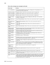
... service check" on page 2-54. 927.03 Fan Stalled RIP Fan-Go to "927.03 error code service check" on page 2-55. 930.09 LV Power Supply Unable to "940.xx error code service check" on Magenta page 2-58. 942.xx TMC Error- Replace that part with a new FRU. 951.xx NVRAM...
... service check" on page 2-54. 927.03 Fan Stalled RIP Fan-Go to "927.03 error code service check" on page 2-55. 930.09 LV Power Supply Unable to "940.xx error code service check" on Magenta page 2-58. 942.xx TMC Error- Replace that part with a new FRU. 951.xx NVRAM...
Service Manual
Page 99
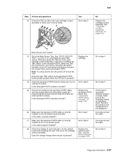
.... Correctly connect the cable. Is the developer HVPS cracked or broken? 5 Check the mounting of the developer HVPS. Make sure the screws that mount the power supply are tightened down and the board is correctly installed on the system board. Does the voltage change when the pin is incorrectly installed, install it...
.... Correctly connect the cable. Is the developer HVPS cracked or broken? 5 Check the mounting of the developer HVPS. Make sure the screws that mount the power supply are tightened down and the board is correctly installed on the system board. Does the voltage change when the pin is incorrectly installed, install it...
Service Manual
Page 101
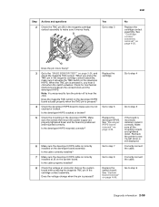
... on page 3-24, and check the magenta TMC sensor. Recheck the printer to step 8 Replace the system board. Make sure the screws that mount the power supply are tightened down and the board is pressed? 4 Check the developer HVPS board to make sure it correctly. Correctly connect the cable. Is the developer...
... on page 3-24, and check the magenta TMC sensor. Recheck the printer to step 8 Replace the system board. Make sure the screws that mount the power supply are tightened down and the board is pressed? 4 Check the developer HVPS board to make sure it correctly. Correctly connect the cable. Is the developer...

Service Manual
Page 103
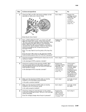
... the cable. See "Cartridge contact assembly removal" on page 4-89. When you hear a click when the switch actuates. Make sure the screws that mount the power supply are tightened down and the board is pressed in, you press the TMC pin in the cartridge contact assembly. Go to step 3 No Replace the...
... the cable. See "Cartridge contact assembly removal" on page 4-89. When you hear a click when the switch actuates. Make sure the screws that mount the power supply are tightened down and the board is pressed in, you press the TMC pin in the cartridge contact assembly. Go to step 3 No Replace the...
Service Manual
Page 105
...-1 on page 4-39. Replace the cartridge. Correctly connect the cable. When you hear a click when the switch actuates. Make sure the screws that mount the power supply are tightened down and the board is incorrectly installed, install it actuates the TMC switch on the system board. Is the cable correctly installed? 7 Make...
...-1 on page 4-39. Replace the cartridge. Correctly connect the cable. When you hear a click when the switch actuates. Make sure the screws that mount the power supply are tightened down and the board is incorrectly installed, install it actuates the TMC switch on the system board. Is the cable correctly installed? 7 Make...
Service Manual
Page 116
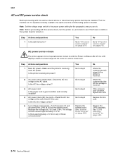
... step 2 Go to step 3 Go to step 4 Go to the printer is incorrect. No Inform the customer that AC power to step 5 Replace the system board. Is the AC line voltage correct? 5 Low voltage power supply-Turn the power off , the LCD display is in . Is there approximately +5 V dc on ? Yes Go to "AC... power service check" on , and no motors turn the printer on, and check to see if the Power on LED on the system board is turned on...
... step 2 Go to step 3 Go to step 4 Go to the printer is incorrect. No Inform the customer that AC power to step 5 Replace the system board. Is the AC line voltage correct? 5 Low voltage power supply-Turn the power off , the LCD display is in . Is there approximately +5 V dc on ? Yes Go to "AC... power service check" on , and no motors turn the printer on, and check to see if the Power on LED on the system board is turned on...

Service Manual
Page 151
... of support. Step 1 2 3 Actions and questions Second transfer roll assembly-Check the second transfer roll for correct installation. Transfer high voltage power supply, HV wiring, and contacts-Check the second transfer cable (transfer HVPS contact to the second transfer roll rear arm contact) for any checks ... information 2-109 Is there any problems with only one color • Light or very light print CAUTION Make sure the printer is powered off before making any signs of toner buildup, surface damage to "Print quality service check" on the second transfer roll or associated ...
... of support. Step 1 2 3 Actions and questions Second transfer roll assembly-Check the second transfer roll for correct installation. Transfer high voltage power supply, HV wiring, and contacts-Check the second transfer cable (transfer HVPS contact to the second transfer roll rear arm contact) for any checks ... information 2-109 Is there any problems with only one color • Light or very light print CAUTION Make sure the printer is powered off before making any signs of toner buildup, surface damage to "Print quality service check" on the second transfer roll or associated ...
Service Manual
Page 183
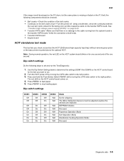
.... • Transfer HVPS board • Engine board HCIT standalone test mode This test lets you want to the transfer HVPS board. Turn the HCIT power off for shipping The Mirror Reflection Sensors must be checked: • Bell cranks-Check the condition of the bell cranks. • Continuity on page ...cable-Make sure that there is missing or faded on the ITU belt, the following steps to set and run . 2. See "Transfer high voltage power supply (HVPS)" on the bell crank circuit-Turn the printer off. Use the Dip Switch Settings table to determine the settings (DSW1 thru DSW4) on the...
.... • Transfer HVPS board • Engine board HCIT standalone test mode This test lets you want to the transfer HVPS board. Turn the HCIT power off for shipping The Mirror Reflection Sensors must be checked: • Bell cranks-Check the condition of the bell cranks. • Continuity on page ...cable-Make sure that there is missing or faded on the ITU belt, the following steps to set and run . 2. See "Transfer high voltage power supply (HVPS)" on the bell crank circuit-Turn the printer off. Use the Dip Switch Settings table to determine the settings (DSW1 thru DSW4) on the...
Service Manual
Page 321
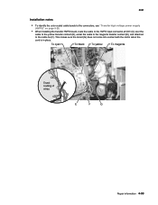
Repair information 4-93 5061 Installation notes • To identify the color coded cable bands to the connectors, see "Transfer high voltage power supply (HVPS)" on page 5-20. • When installing the transfer HVPS board, route the cable to the HVPS input connector at CN1 (C) over the cable to the yellow transfer contact (D), under the cable to the magenta transfer contact (E), and attached to the cable tie (F). This makes sure the toroid (G) does not come into contact with the motor when the card is in place.
Repair information 4-93 5061 Installation notes • To identify the color coded cable bands to the connectors, see "Transfer high voltage power supply (HVPS)" on page 5-20. • When installing the transfer HVPS board, route the cable to the HVPS input connector at CN1 (C) over the cable to the yellow transfer contact (D), under the cable to the magenta transfer contact (E), and attached to the cable tie (F). This makes sure the toroid (G) does not come into contact with the motor when the card is in place.
Service Manual
Page 344
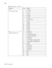
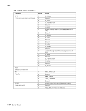
5061 See "System board" on page 5-7. Connector J18 Low voltage power supply J19 Magenta/cyan BLDC motors Pin no. 1 2 3 4 5 6 7 8 9 10 11 12 13 14 15 16 1 2 3 4 5 6 7 8 9 10 11 12 13 14 15 16 17 18 Signal +3.3 V dc +3.3 V dc +5 V dc +5 V dc +24V dc +24V dc +24V dc +3.3 V dc Sense Ground Ground Ground Ground Ground Ground Ground Ground M_ON_OUT C_ON_OUT +5V dc (Through fuse F8) +5V dc (Through fuse F8) M_DIR_OUT C_DIR_OUT +24V_M_AND_C (Through fuse F5) +24V_M_AND_C (Through fuse F5) Ground Ground M_CLK_OUT C_CLK_OUT M_HALL_IN C_HALL_IN N/C N/C N/C N/C 5-12 Service Manual
5061 See "System board" on page 5-7. Connector J18 Low voltage power supply J19 Magenta/cyan BLDC motors Pin no. 1 2 3 4 5 6 7 8 9 10 11 12 13 14 15 16 1 2 3 4 5 6 7 8 9 10 11 12 13 14 15 16 17 18 Signal +3.3 V dc +3.3 V dc +5 V dc +5 V dc +24V dc +24V dc +24V dc +3.3 V dc Sense Ground Ground Ground Ground Ground Ground Ground Ground M_ON_OUT C_ON_OUT +5V dc (Through fuse F8) +5V dc (Through fuse F8) M_DIR_OUT C_DIR_OUT +24V_M_AND_C (Through fuse F5) +24V_M_AND_C (Through fuse F5) Ground Ground M_CLK_OUT C_CLK_OUT M_HALL_IN C_HALL_IN N/C N/C N/C N/C 5-12 Service Manual
Service Manual
Page 346
... Ground +5 V dc (through fuse F12 and safety switches at J10) C_LENA Ground C_THERMISTOR Y_DATAGround Y_DATA+ FAN1_STALL_IN Ground FAN1_CNTRL +24V_LEFTSIDE Ground +5 V dc (direct from low voltage power supply) Ground VDO_ERR (+5 V dc to J8 and J12) 5-14 Service Manual
... Ground +5 V dc (through fuse F12 and safety switches at J10) C_LENA Ground C_THERMISTOR Y_DATAGround Y_DATA+ FAN1_STALL_IN Ground FAN1_CNTRL +24V_LEFTSIDE Ground +5 V dc (direct from low voltage power supply) Ground VDO_ERR (+5 V dc to J8 and J12) 5-14 Service Manual
Service Manual
Page 354
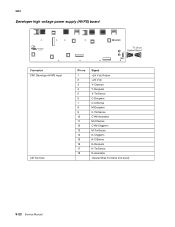
5061 Developer high voltage power supply (HVPS) board Connector CN1 Developer HVPS Input CB Terminal Pin no 1 2 3 4 5 6 7 8 9 10 11 12 13 14 15 16 17 18 Signal +24 V dc Return +24 V dc Y-Ctsense Y-Devpwm Y-TnrSense C-Devpwm C-CtSense M-Devpwm C-TnrSense CYM-Acenable M-CtSense CYM-Chgpwm M-TnrSense K-Chgpwm K-CtSense K-Devpwm K-TnrSense K-Acenable Cleaner Bias Terminal (not used) 5-22 Service Manual
5061 Developer high voltage power supply (HVPS) board Connector CN1 Developer HVPS Input CB Terminal Pin no 1 2 3 4 5 6 7 8 9 10 11 12 13 14 15 16 17 18 Signal +24 V dc Return +24 V dc Y-Ctsense Y-Devpwm Y-TnrSense C-Devpwm C-CtSense M-Devpwm C-TnrSense CYM-Acenable M-CtSense CYM-Chgpwm M-TnrSense K-Chgpwm K-CtSense K-Devpwm K-TnrSense K-Acenable Cleaner Bias Terminal (not used) 5-22 Service Manual
Service Manual
Page 355
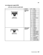
5061 Low voltage power supply (LVPS) LVPS cable connectors to system board Connector Main power to system board (J35) LVPS to system board cable for fuser (J17) Pin Signal 1 +3.3 V dc 2 +3.3 V dc 3 +5 V dc 4 +5 V dc 5 +24 V dc 6 +24 V dc 7 +24 V dc 8 +3.3 V dc ...
5061 Low voltage power supply (LVPS) LVPS cable connectors to system board Connector Main power to system board (J35) LVPS to system board cable for fuser (J17) Pin Signal 1 +3.3 V dc 2 +3.3 V dc 3 +5 V dc 4 +5 V dc 5 +24 V dc 6 +24 V dc 7 +24 V dc 8 +3.3 V dc ...


