Owner's Manual (English)
Page 4
...Panel Information 5 Stand Installation 6 Attaching the TV to a Wall 7 Back Cover for PC Mode 25 AV Output Setup 26 ...Digital Audio Output Setup 27 WATCHING TV/PROGRAMME CONTROL Remote Control Key Functions 28 Turning on the TV 30 Initializing Setup 30 Programme Selection 31 ...Key Lock 45 ...SIMPLINK 47 ...Digital Signal Strength 48 PICTURE CONTROL Picture Size(Aspect Ratio) Control 49 Preset Picture Settings - SSM Mode 62 Sound Setting Adjustment - PSM - Picture Improvement Technology 56 Advanced - Screen Setup for Wire Arrangement 8 Desktop Pedestal Installation 9 Wall...
...Panel Information 5 Stand Installation 6 Attaching the TV to a Wall 7 Back Cover for PC Mode 25 AV Output Setup 26 ...Digital Audio Output Setup 27 WATCHING TV/PROGRAMME CONTROL Remote Control Key Functions 28 Turning on the TV 30 Initializing Setup 30 Programme Selection 31 ...Key Lock 45 ...SIMPLINK 47 ...Digital Signal Strength 48 PICTURE CONTROL Picture Size(Aspect Ratio) Control 49 Preset Picture Settings - SSM Mode 62 Sound Setting Adjustment - PSM - Picture Improvement Technology 56 Advanced - Screen Setup for Wire Arrangement 8 Desktop Pedestal Installation 9 Wall...
Owner's Manual (English)
Page 5
Off Setting 73 PARENTAL CONTROL/RATINGS Set Password & Lock System 74 Programme Blocking 76 Parental Guidance 77 External Input Blocking 78 TELETEXT Switch On/Off 79 Simple Text 79 TOP Text 79 Fastext 80 Special Teletext Functions 80 APPENDIX Troubleshooting 81 Maintenance 83 Product Specifications 84 Programming the Remote Control 85 IR Codes 87 External Control Through RS-232C 90 After reading this manual, keep it handy for future reference. 3 CONTENTS TIME SETTING Clock Setting 69 Auto On/Off Timer Setting 71 Sleep Timer Setting 72 Auto Shut -
Off Setting 73 PARENTAL CONTROL/RATINGS Set Password & Lock System 74 Programme Blocking 76 Parental Guidance 77 External Input Blocking 78 TELETEXT Switch On/Off 79 Simple Text 79 TOP Text 79 Fastext 80 Special Teletext Functions 80 APPENDIX Troubleshooting 81 Maintenance 83 Product Specifications 84 Programming the Remote Control 85 IR Codes 87 External Control Through RS-232C 90 After reading this manual, keep it handy for future reference. 3 CONTENTS TIME SETTING Clock Setting 69 Auto On/Off Timer Setting 71 Sleep Timer Setting 72 Auto Shut -
Owner's Manual (English)
Page 6
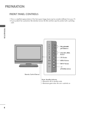
Image shown may be somewhat different from your product has a protection film attached, remove the film and then wipe the product with a polishing cloth. PREPARATION PR VOL OK MENU R INPUT PROGRAMME (D,E)Button VOLUME (F,G) Button OK Button MENU Button INPUT Button (POWER) Button Remote Control Sensor Power Standby Indicator • Illuminates red in standby mode. • Illuminates green when the set is a simplified representation of the front panel. PREPARATION FRONT PANEL CONTROLS I If your TV. I This is switched on. 4
Image shown may be somewhat different from your product has a protection film attached, remove the film and then wipe the product with a polishing cloth. PREPARATION PR VOL OK MENU R INPUT PROGRAMME (D,E)Button VOLUME (F,G) Button OK Button MENU Button INPUT Button (POWER) Button Remote Control Sensor Power Standby Indicator • Illuminates red in standby mode. • Illuminates green when the set is a simplified representation of the front panel. PREPARATION FRONT PANEL CONTROLS I If your TV. I This is switched on. 4
Owner's Manual (English)
Page 7
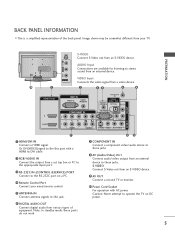
... not work. MI/DVI IN 6 DIGITAL AUDIO OUT Connect digital audio from an S-VIDEO device. Caution: Never attempt to operate the TV on a PC. 4 Remote Control Port Connect your TV. PREPARATION VIDEO L/MONO AUDIO R VIDEO L/MONO AUDIO R VIDEO L/MONO AUDIO R S-VIDEO S-VIDEO S-VIDEO Connect S-Video out from...S-VIDEO Connect S-Video out from an S-VIDEO device. 9 AV OUT Connect a second TV or monitor. 10 Power Cord Socket For operation with a HDMI to DVI cable. 2 ANTENNA IN RGB/AUDIO IN DIGITAL Connect the output from a set top box or PC to stereo sound from a video device. 2 34 5 6...
... not work. MI/DVI IN 6 DIGITAL AUDIO OUT Connect digital audio from an S-VIDEO device. Caution: Never attempt to operate the TV on a PC. 4 Remote Control Port Connect your TV. PREPARATION VIDEO L/MONO AUDIO R VIDEO L/MONO AUDIO R VIDEO L/MONO AUDIO R S-VIDEO S-VIDEO S-VIDEO Connect S-Video out from...S-VIDEO Connect S-Video out from an S-VIDEO device. 9 AV OUT Connect a second TV or monitor. 10 Power Cord Socket For operation with a HDMI to DVI cable. 2 ANTENNA IN RGB/AUDIO IN DIGITAL Connect the output from a set top box or PC to stereo sound from a video device. 2 34 5 6...
Owner's Manual (English)
Page 9
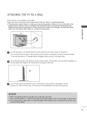
... eye-bolts position before inserting the eye-bolts, loosen the bolts.) * Insert the eye-bolts or TV brackets/bolts and tighten them securely in the forward direction. G To use the product safely make sure... caused by fall. A The instructions shown below is a safer way to set up close to fix it is pushed backwards. A Set it up the product, which is to the wall so the product doesn't...product. ! It will also prevent the product from the product. 1 2 PREPARATION 1 Use the eye-bolts or TV brackets/bolts to fix the product to the wall as that is mounted on the wall. 3 3 Use a...
... eye-bolts position before inserting the eye-bolts, loosen the bolts.) * Insert the eye-bolts or TV brackets/bolts and tighten them securely in the forward direction. G To use the product safely make sure... caused by fall. A The instructions shown below is a safer way to set up close to fix it is pushed backwards. A Set it up the product, which is to the wall so the product doesn't...product. ! It will also prevent the product from the product. 1 2 PREPARATION 1 Use the eye-bolts or TV brackets/bolts to fix the product to the wall as that is mounted on the wall. 3 3 Use a...
Owner's Manual (English)
Page 14
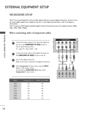
This TV supports HDCP (High-bandwidth Digital Contents Protection) protocol for the digital set-top box.) 4 Select Component 1 input source using the INPUT button on the set -top box. (Refer to the COMPONENT IN VIDEO 1 jacks on the remote control. RGB IN When connecting with a Component ...DIGITAL AUDIO OUT However, if you do receive digital signals from a digital set -top box. EXTERNAL EQUIPMENT SETUP HD RECEIVER SETUP This TV can receive Digital Over-the-air/Cable signals without an external digital set -top box or other digital external device, refer to COMPONENT IN 2 ...
This TV supports HDCP (High-bandwidth Digital Contents Protection) protocol for the digital set-top box.) 4 Select Component 1 input source using the INPUT button on the set -top box. (Refer to the COMPONENT IN VIDEO 1 jacks on the remote control. RGB IN When connecting with a Component ...DIGITAL AUDIO OUT However, if you do receive digital signals from a digital set -top box. EXTERNAL EQUIPMENT SETUP HD RECEIVER SETUP This TV can receive Digital Over-the-air/Cable signals without an external digital set -top box or other digital external device, refer to COMPONENT IN 2 ...
Owner's Manual (English)
Page 15
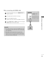
... box supports Auto HDMI function, the output resolution of the source device to 1280x720p. G If the digital set-top box player does not support Auto HDMI, you need to set to 1280x720p. RGB IN When connecting with HDMI cable RGB(PC) AUDIO (RGB/DVI) DIGITAL AUDIO OUT COMPONENT IN 1 Connect the digital... set-top box to HDMI/DVI IN 1 or 2 jack on the remote control. To get the best picture quality, adjust the output resolution of the source ...
... box supports Auto HDMI function, the output resolution of the source device to 1280x720p. G If the digital set-top box player does not support Auto HDMI, you need to set to 1280x720p. RGB IN When connecting with HDMI cable RGB(PC) AUDIO (RGB/DVI) DIGITAL AUDIO OUT COMPONENT IN 1 Connect the digital... set-top box to HDMI/DVI IN 1 or 2 jack on the remote control. To get the best picture quality, adjust the output resolution of the source ...
Owner's Manual (English)
Page 16
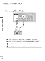
...-DTV OUTPUT L R 1 Connect the DVI output of the digital set-top box to the HDMI/DVI IN 1 jack on the set. 2 Connect the audio output of the digital set-top box to the AUDIO(RGB/DVI) jack on the set. 3 Turn on the digital set-top box. (Refer to the owner's manual for the digital... set-top box.) 4 Select HDMI1/DVI input source using the INPUT...
...-DTV OUTPUT L R 1 Connect the DVI output of the digital set-top box to the HDMI/DVI IN 1 jack on the set. 2 Connect the audio output of the digital set-top box to the AUDIO(RGB/DVI) jack on the set. 3 Turn on the digital set-top box. (Refer to the owner's manual for the digital... set-top box.) 4 Select HDMI1/DVI input source using the INPUT...
Owner's Manual (English)
Page 17
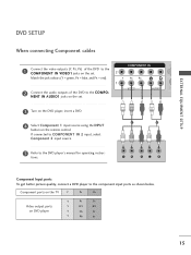
... ports as shown below. RGB IN RGB (PC) COMPONENT IN DIGI AUDIO (C VIDEO AUDIO S- Component ports on the TV Y PB PR Video output ports on the remote control. NENT IN AUDIO1 jacks on the set . Match the jack colours (Y = green, PB = blue, and PR = red). 1 (DVI) 2 Connect the ...audio outputs of the2DVD to the COMPONENT IN VIDEO1 jacks on the set . 3 Turn on the DVD player, insert a DVD. 4 Select Component 1 input source using the INPUT button on DVD player Y PB PR Y B-Y R-Y Y Cb Cr Y...
... ports as shown below. RGB IN RGB (PC) COMPONENT IN DIGI AUDIO (C VIDEO AUDIO S- Component ports on the TV Y PB PR Video output ports on the remote control. NENT IN AUDIO1 jacks on the set . Match the jack colours (Y = green, PB = blue, and PR = red). 1 (DVI) 2 Connect the ...audio outputs of the2DVD to the COMPONENT IN VIDEO1 jacks on the set . 3 Turn on the DVD player, insert a DVD. 4 Select Component 1 input source using the INPUT button on DVD player Y PB PR Y B-Y R-Y Y Cb Cr Y...
Owner's Manual (English)
Page 18
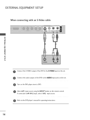
... AUDIO S-VIDEO VIDEO (MONO) AUDIO 1 2 AV IN 1 EXTERNAL EQUIPMENT SETUP S-VIDEO L R AUDIO 1 Connect the S-VIDEO output of the DVD to the S-VIDEO input on the set . 3 Turn on the DVD player, insert a DVD. 4 Select A V 1 input source using the INPUT button on the remote control. If connected to AV IN 2 input, select... A V 2 input source. 5 Refer to the AUDIO input jacks on the set . 2 Connect the audio outputs of the DVD to the DVD player's manual for operating instructions. 16
... AUDIO S-VIDEO VIDEO (MONO) AUDIO 1 2 AV IN 1 EXTERNAL EQUIPMENT SETUP S-VIDEO L R AUDIO 1 Connect the S-VIDEO output of the DVD to the S-VIDEO input on the set . 3 Turn on the DVD player, insert a DVD. 4 Select A V 1 input source using the INPUT button on the remote control. If connected to AV IN 2 input, select... A V 2 input source. 5 Refer to the AUDIO input jacks on the set . 2 Connect the audio outputs of the DVD to the DVD player's manual for operating instructions. 16
Owner's Manual (English)
Page 19
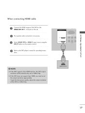
...-DVD OUTPUT 17 To get the best picture quality, adjust the output resolution of the DVD to the HDMI/DVI IN 1 or 2 jack on the set. 2 No separate audio connection is necessary. 3 Select HDMI1/DVI or HDMI 2 input source using the INPUT button on the remote control. 4 Refer to...1 (DVI) RGB IN RGB (PC) A (R COMPONENT IN VIDEO AUDIO 1 ! NOTE G If the DVD supports Auto HDMI function, the DVD output resolution will be automatically set the output resolution appropriately. tions. EXTERNAL EQUIPMENT SETUP When connecting HDMI cable 1 Connect the HDMI output of the DVD to 1280x720p.
...-DVD OUTPUT 17 To get the best picture quality, adjust the output resolution of the DVD to the HDMI/DVI IN 1 or 2 jack on the set. 2 No separate audio connection is necessary. 3 Select HDMI1/DVI or HDMI 2 input source using the INPUT button on the remote control. 4 Refer to...1 (DVI) RGB IN RGB (PC) A (R COMPONENT IN VIDEO AUDIO 1 ! NOTE G If the DVD supports Auto HDMI function, the DVD output resolution will be automatically set the output resolution appropriately. tions. EXTERNAL EQUIPMENT SETUP When connecting HDMI cable 1 Connect the HDMI output of the DVD to 1280x720p.
Owner's Manual (English)
Page 20
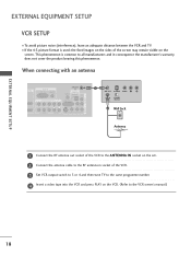
...IN OUTPUT SWITCH 2 Wall Jack HDMI/DVI IN 2 1 (DVI) Antenna 1 Connect the RF antenna out socket of the VCR to the ANTENNA I N socket on the set. 2 Connect the antenna cable to the RF antenna in socket of the screen may remain visible on the VCR. (Refer to all manufacturers and in... consequence the manufacturer's warranty does not cover the product bearing this phenomenon. the fixed images on the sides of the VCR. 3 Set VCR output switch to 3 or 4 and then tune TV to the same programme number. 4 Insert a video tape into the VCR and press PLAY on the screen. I To avoid picture noise...
...IN OUTPUT SWITCH 2 Wall Jack HDMI/DVI IN 2 1 (DVI) Antenna 1 Connect the RF antenna out socket of the VCR to the ANTENNA I N socket on the set. 2 Connect the antenna cable to the RF antenna in socket of the screen may remain visible on the VCR. (Refer to all manufacturers and in... consequence the manufacturer's warranty does not cover the product bearing this phenomenon. the fixed images on the sides of the VCR. 3 Set VCR output switch to 3 or 4 and then tune TV to the same programme number. 4 Insert a video tape into the VCR and press PLAY on the screen. I To avoid picture noise...
Owner's Manual (English)
Page 21
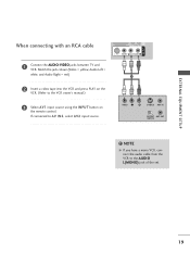
...) DIGITAL AUDIO OUT COMPONENT IN 2 When connecting with an RCA cable 1 (DVI) VIDEO AUDIO AUDIO S-VIDEO VIDEO (MONO) AUDIO 1 Connect the AUDIO/VIDEO jacks between TV and VCR. Match the jack colours(Video = yellow, Audio Left = white, and Audio Right = red) 1 2 Insert a video tape into the VCR and press PLAY on... ANTENNA IN DIGITAL AUDIO OUT ! NOTE G If you have a mono VCR, connect the audio cable from the VCR to the AUDIO L(MONO) jack of the set. 19
...) DIGITAL AUDIO OUT COMPONENT IN 2 When connecting with an RCA cable 1 (DVI) VIDEO AUDIO AUDIO S-VIDEO VIDEO (MONO) AUDIO 1 Connect the AUDIO/VIDEO jacks between TV and VCR. Match the jack colours(Video = yellow, Audio Left = white, and Audio Right = red) 1 2 Insert a video tape into the VCR and press PLAY on... ANTENNA IN DIGITAL AUDIO OUT ! NOTE G If you have a mono VCR, connect the audio cable from the VCR to the AUDIO L(MONO) jack of the set. 19
Owner's Manual (English)
Page 22
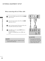
... RGB (PC) When connecting with an S-Video cable COMPONENT IN 2 1 Connect the S-VIDEO1 (DoVIu) tput of the VCR to the AUDIO input jacks on the set. 1 2 3 Insert a video tape into the VCR and press PLAY on the VCR. (Refer to the VCR owner's manual.) 4 Select AV1 input source using the INPUT...
... RGB (PC) When connecting with an S-Video cable COMPONENT IN 2 1 Connect the S-VIDEO1 (DoVIu) tput of the VCR to the AUDIO input jacks on the set. 1 2 3 Insert a video tape into the VCR and press PLAY on the VCR. (Refer to the VCR owner's manual.) 4 Select AV1 input source using the INPUT...
Owner's Manual (English)
Page 23
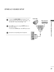
S-VIDEO 1 VIDEO L/MONO AUDIO R AV IN 2 21 VIDEO L R 3 Operate the corresponding external equipment. Match the jack colours.(Video = yel- low, Audio Left = white, and Audio Right = red) Camcorder Video Game Set 2 Select AV2 input source using the INPUT button on the remote control. EXTERNAL EQUIPMENT SETUP OTHER A/V SOURCE SETUP 1 Connect the AUDIO/VIDEO jacks between TV and external equipment. If connected to AV IN1 input, select AV1 input source.
S-VIDEO 1 VIDEO L/MONO AUDIO R AV IN 2 21 VIDEO L R 3 Operate the corresponding external equipment. Match the jack colours.(Video = yel- low, Audio Left = white, and Audio Right = red) Camcorder Video Game Set 2 Select AV2 input source using the INPUT button on the remote control. EXTERNAL EQUIPMENT SETUP OTHER A/V SOURCE SETUP 1 Connect the AUDIO/VIDEO jacks between TV and external equipment. If connected to AV IN1 input, select AV1 input source.
Owner's Manual (English)
Page 24
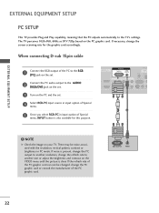
...pattern, contrast or brightness in input option of Special menu, INPUT button is also available for the graphic card accordingly. VIDEO 3AUDIOTurn on the set . If the refresh rate of the PC graphic card. NOTE G Check the image on the VIDEO menu until the picture is present,...purpose. If noise is clear. RGB OUTPUT AUDIO 22 COMPONENT IN 2 Connect the PC audio output to the TV's settings. EXTERNAL EQUIPMENT SETUP EXTERNAL EQUIPMENT SETUP PC SETUP This TV provides Plug and Play capability, meaning that the PC adjusts automatically to the AUDIO (RGB/DVI) jack on ...
...pattern, contrast or brightness in input option of Special menu, INPUT button is also available for the graphic card accordingly. VIDEO 3AUDIOTurn on the set . If the refresh rate of the PC graphic card. NOTE G Check the image on the VIDEO menu until the picture is present,...purpose. If noise is clear. RGB OUTPUT AUDIO 22 COMPONENT IN 2 Connect the PC audio output to the TV's settings. EXTERNAL EQUIPMENT SETUP EXTERNAL EQUIPMENT SETUP PC SETUP This TV provides Plug and Play capability, meaning that the PC adjusts automatically to the AUDIO (RGB/DVI) jack on ...
Owner's Manual (English)
Page 25
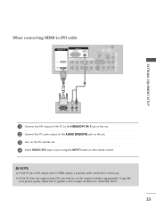
... does not support Auto DVI, you need to 1024x768, 60Hz. 23 To get the best picture quality, adjust the PC graphics card's output resolution to set . 4 Select HDMI1/DVI input source using the INPUT button on the remote control. ! When connecting HDMI to DVI cable HDMI/DVI IN 2 1 (DVI) RGB IN... OUT HDMI/DV (DVI) EXTERNAL EQUIPMENT SETUP DVI-PC OUTPUT L R 1 Connect the DVI output of the PC to the HDMI/DVI IN 1jack on the set. 2 Connect the PC audio output to the AUDIO (RGB/DVI) jack on the...
... does not support Auto DVI, you need to 1024x768, 60Hz. 23 To get the best picture quality, adjust the PC graphics card's output resolution to set . 4 Select HDMI1/DVI input source using the INPUT button on the remote control. ! When connecting HDMI to DVI cable HDMI/DVI IN 2 1 (DVI) RGB IN... OUT HDMI/DV (DVI) EXTERNAL EQUIPMENT SETUP DVI-PC OUTPUT L R 1 Connect the DVI output of the PC to the HDMI/DVI IN 1jack on the set. 2 Connect the PC audio output to the AUDIO (RGB/DVI) jack on the...
Owner's Manual (English)
Page 26
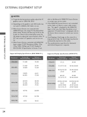
...28.125 33.72/33.75 50.00 59.94/60.00 1920x1080p 67.432/67.500 56.25 26.97/27.00 33.71/33.75 59.939/60.00 50.00 23.97/24.00 29....13 59.799 59.65 24 G When Source Devices are connected with HDMI/DVI Input, output TV SET Resolution (480p, 576p, 720p, 1080i, 1080p) and TV SET Display fit EIA/CEA-861-B Specification to the Cable or if there is a poor cable connection... input form for a long period of time. The fixed image may not work if a HDMI to the Manual of the TV SET and contact a PC graphics card service center. G If the HDMI/DVI Source Device is displayed, refer to 1280x768, 60Hz....
...28.125 33.72/33.75 50.00 59.94/60.00 1920x1080p 67.432/67.500 56.25 26.97/27.00 33.71/33.75 59.939/60.00 50.00 23.97/24.00 29....13 59.799 59.65 24 G When Source Devices are connected with HDMI/DVI Input, output TV SET Resolution (480p, 576p, 720p, 1080i, 1080p) and TV SET Display fit EIA/CEA-861-B Specification to the Cable or if there is a poor cable connection... input form for a long period of time. The fixed image may not work if a HDMI to the Manual of the TV SET and contact a PC graphics card service center. G If the HDMI/DVI Source Device is displayed, refer to 1280x768, 60Hz....
Owner's Manual (English)
Page 27
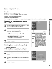
.... If the results are unsatisfactory, adjust your monitor's position, size and phase manually. Clock This function is -32 ~ +32. Resolution Position Clock Phase Reset Initialize Settings Yes No MENU Prev F G Select OK 123 25 Resolution function works only RGB-PC mode. (1024/1280/1360/1366x768, 60Hz) Note: Some signal from some...
.... If the results are unsatisfactory, adjust your monitor's position, size and phase manually. Clock This function is -32 ~ +32. Resolution Position Clock Phase Reset Initialize Settings Yes No MENU Prev F G Select OK 123 25 Resolution function works only RGB-PC mode. (1024/1280/1360/1366x768, 60Hz) Note: Some signal from some...
Owner's Manual (English)
Page 28
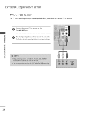
...AUDIO ! G We recommend to use the AV OUT jacks for AV out. EXTERNAL EQUIPMENT SETUP AV OUTPUT SETUP The TV has a special signal output capability which allows you to the TV's AV OUT jacks. NOTE G Digital, Component1-2, RGB-PC, HDMI1/DVI, HDMI2 input sources cannot be used for ...VCR recording. 1 VIDEO L R S-VIDEO EXTERNAL EQUIPMENT SETUP 26 COMPONENT IN 2 2 See the Operating Manual of the second TV or monitor for fur1th(DeVrI) details regarding that device's input settings. AV IN 1 AV OUT HDMI/DVI IN RGB IN RGB (PC) 1 Connect the ...
...AUDIO ! G We recommend to use the AV OUT jacks for AV out. EXTERNAL EQUIPMENT SETUP AV OUTPUT SETUP The TV has a special signal output capability which allows you to the TV's AV OUT jacks. NOTE G Digital, Component1-2, RGB-PC, HDMI1/DVI, HDMI2 input sources cannot be used for ...VCR recording. 1 VIDEO L R S-VIDEO EXTERNAL EQUIPMENT SETUP 26 COMPONENT IN 2 2 See the Operating Manual of the second TV or monitor for fur1th(DeVrI) details regarding that device's input settings. AV IN 1 AV OUT HDMI/DVI IN RGB IN RGB (PC) 1 Connect the ...


