Owner's Manual (English)
Page 4
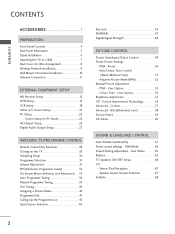
... the Programme List 43 Input Source Selection 44 Key Lock 45 ...SIMPLINK 47 ...Digital Signal Strength 48 PICTURE CONTROL Picture Size(Aspect Ratio) Control 49 Preset Picture Settings - Screen Setup for Wire Arrangement 8 Desktop Pedestal Installation 9 Wall Mount: Horizontal installation 10 Antenna Connection 11 EXTERNAL EQUIPMENT SETUP HD Receiver Setup 12 DVD Setup 15 ...VCR Setup 18 ...Other A/V Source Setup 21 PC Setup 22 ...- PSM - User Mode 63 Balance 65 TV Speakers ON/OFF Setup 66 I/II - User Option 53 Colour Tone - User Option 54 Brightness Adjustment 55 XD...
... the Programme List 43 Input Source Selection 44 Key Lock 45 ...SIMPLINK 47 ...Digital Signal Strength 48 PICTURE CONTROL Picture Size(Aspect Ratio) Control 49 Preset Picture Settings - Screen Setup for Wire Arrangement 8 Desktop Pedestal Installation 9 Wall Mount: Horizontal installation 10 Antenna Connection 11 EXTERNAL EQUIPMENT SETUP HD Receiver Setup 12 DVD Setup 15 ...VCR Setup 18 ...Other A/V Source Setup 21 PC Setup 22 ...- PSM - User Mode 63 Balance 65 TV Speakers ON/OFF Setup 66 I/II - User Option 53 Colour Tone - User Option 54 Brightness Adjustment 55 XD...
Owner's Manual (English)
Page 7
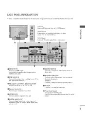
... (CONTROL&SERVICE) R AUDIO L/MONO VIDEO 1 2 COMPONENT IN VARIABLE AUDIO OUT HDMI/DVI IN AV IN 2 AV IN 2 VIDEO Input Connects the video signal from an external device. S-VIDEO Connect S-Video out from an S-VIDEO device. 9 AV OUT Connect a second TV or monitor. 10 Power Cord Socket For operation with a HDMI to DVI cable. 2 ANTENNA IN RGB/AUDIO IN DIGITAL Connect the output from a set top box or PC to stereo sound from a video device. 2 34 5 6 RGB IN RGB (PC) AUDIO (RGB/DVI) ANTENNA IN REMOTE CONTROL IN DIGITAL AUDIO OUT OPTICAL VIDEO...
... (CONTROL&SERVICE) R AUDIO L/MONO VIDEO 1 2 COMPONENT IN VARIABLE AUDIO OUT HDMI/DVI IN AV IN 2 AV IN 2 VIDEO Input Connects the video signal from an external device. S-VIDEO Connect S-Video out from an S-VIDEO device. 9 AV OUT Connect a second TV or monitor. 10 Power Cord Socket For operation with a HDMI to DVI cable. 2 ANTENNA IN RGB/AUDIO IN DIGITAL Connect the output from a set top box or PC to stereo sound from a video device. 2 34 5 6 RGB IN RGB (PC) AUDIO (RGB/DVI) ANTENNA IN REMOTE CONTROL IN DIGITAL AUDIO OUT OPTICAL VIDEO...
Owner's Manual (English)
Page 14
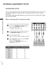
... DIGITAL AUDIO OUT Match the jack colors 1 (DVI) (Y = green, PB = blue, and PR = red) 2 Connect the audio output of the digital2 set . This TV supports HDCP (High-bandwidth Digital Contents Protection) protocol for the digital set-top box.) 4 Select Component 1 input source using the INPUT button on the set top box to the COMPONENT IN VIDEO 1 jacks on the remote control. However, if you do receive digital signals from a digital set -top box. EXTERNAL EQUIPMENT SETUP HD RECEIVER SETUP This TV can receive Digital Over-the-air/Cable signals without an external digital set -top box...
... DIGITAL AUDIO OUT Match the jack colors 1 (DVI) (Y = green, PB = blue, and PR = red) 2 Connect the audio output of the digital2 set . This TV supports HDCP (High-bandwidth Digital Contents Protection) protocol for the digital set-top box.) 4 Select Component 1 input source using the INPUT button on the set top box to the COMPONENT IN VIDEO 1 jacks on the remote control. However, if you do receive digital signals from a digital set -top box. EXTERNAL EQUIPMENT SETUP HD RECEIVER SETUP This TV can receive Digital Over-the-air/Cable signals without an external digital set -top box...
Owner's Manual (English)
Page 15
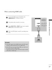
...AUDIO (RGB/DVI) COMPONENT IN VIDEO AUDIO 1 DIGITAL AUDIO OUT EXTERNAL EQUIPMENT SETUP ! To get the best picture quality, adjust the output resolution of the source device will be automatically set -top box supports Auto HDMI function, the output resolution of the source device to 1280x720p. HDMI-DTV OUTPUT 13 NOTE G If the digital set to 1280x720p. VIDEO 2 AUDNIOo separate audio connection is necessary. 3 Turn on the digital set-top box. (Refer to set . G If the digital set-top box player does not support Auto HDMI, you need to the owner's manual for the digital set...
...AUDIO (RGB/DVI) COMPONENT IN VIDEO AUDIO 1 DIGITAL AUDIO OUT EXTERNAL EQUIPMENT SETUP ! To get the best picture quality, adjust the output resolution of the source device will be automatically set -top box supports Auto HDMI function, the output resolution of the source device to 1280x720p. HDMI-DTV OUTPUT 13 NOTE G If the digital set to 1280x720p. VIDEO 2 AUDNIOo separate audio connection is necessary. 3 Turn on the digital set-top box. (Refer to set . G If the digital set-top box player does not support Auto HDMI, you need to the owner's manual for the digital set...
Owner's Manual (English)
Page 16
...) COMPONENT IN ANTENNA IN REMOTE CONTROL IN DIGITAL AUDIO OUT OPTICAL VIDEO RS-232C IN (CONTROL & SERVICE) AUDIO VIDEO AUDIO S-VIDEO VIDEO (MONO) AUDIO 1 2 AV OUT AV IN 1 DVI-DTV OUTPUT L R 1 Connect the DVI output of the digital set-top box to the HDMI/DVI IN 1 jack on the set. 2 Connect the audio output of the digital set-top box to the AUDIO(RGB/DVI) jack on the set. 3 Turn on the digital set-top box. (Refer to the owner's manual for the digital set-top box.) 4 Select HDMI1/DVI input source using the INPUT button...
...) COMPONENT IN ANTENNA IN REMOTE CONTROL IN DIGITAL AUDIO OUT OPTICAL VIDEO RS-232C IN (CONTROL & SERVICE) AUDIO VIDEO AUDIO S-VIDEO VIDEO (MONO) AUDIO 1 2 AV OUT AV IN 1 DVI-DTV OUTPUT L R 1 Connect the DVI output of the digital set-top box to the HDMI/DVI IN 1 jack on the set. 2 Connect the audio output of the digital set-top box to the AUDIO(RGB/DVI) jack on the set. 3 Turn on the digital set-top box. (Refer to the owner's manual for the digital set-top box.) 4 Select HDMI1/DVI input source using the INPUT button...
Owner's Manual (English)
Page 18
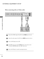
...HDMI/DVI IN RGB IN RGB (PC) DIGITAL AUDIO OUT When connectinCgOMwPOitNhENTaInN S-Video cable 2 AUDIO 1 (DVI) VIDEO AUDIO S-VIDEO VIDEO (MONO) AUDIO 1 2 AV IN 1 EXTERNAL EQUIPMENT SETUP S-VIDEO L R AUDIO 1 Connect the S-VIDEO output of the DVD to the S-VIDEO input on the set. 2 Connect the audio outputs of the DVD to the DVD player's manual for operating instructions. 16 If connected to AV IN 2 input, select A V 2 input source. 5 Refer to the AUDIO input jacks on the set. 3 Turn on the DVD player, insert a DVD. 4 Select A V 1 input source using the INPUT button on the remote...
...HDMI/DVI IN RGB IN RGB (PC) DIGITAL AUDIO OUT When connectinCgOMwPOitNhENTaInN S-Video cable 2 AUDIO 1 (DVI) VIDEO AUDIO S-VIDEO VIDEO (MONO) AUDIO 1 2 AV IN 1 EXTERNAL EQUIPMENT SETUP S-VIDEO L R AUDIO 1 Connect the S-VIDEO output of the DVD to the S-VIDEO input on the set. 2 Connect the audio outputs of the DVD to the DVD player's manual for operating instructions. 16 If connected to AV IN 2 input, select A V 2 input source. 5 Refer to the AUDIO input jacks on the set. 3 Turn on the DVD player, insert a DVD. 4 Select A V 1 input source using the INPUT button on the remote...
Owner's Manual (English)
Page 19
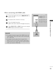
... SETUP When connecting HDMI cable 1 Connect the HDMI output of the DVD to 1280x720p. NOTE G If the DVD supports Auto HDMI function, the DVD output resolution will be automatically set to set . 2 No separate audio connection is necessary. 3 Select HDMI1/DVI or HDMI 2 input source using the INPUT button on the remote control. 4 Refer to the DVD player's manual for operating instruc- G If the DVD does not support Auto HDMI, you need to 1280x720p. HDMI/DVI IN 2 1 (DVI) RGB IN RGB (PC) A (R COMPONENT IN VIDEO AUDIO 1 ! HDMI-DVD OUTPUT 17 To get the best picture...
... SETUP When connecting HDMI cable 1 Connect the HDMI output of the DVD to 1280x720p. NOTE G If the DVD supports Auto HDMI function, the DVD output resolution will be automatically set to set . 2 No separate audio connection is necessary. 3 Select HDMI1/DVI or HDMI 2 input source using the INPUT button on the remote control. 4 Refer to the DVD player's manual for operating instruc- G If the DVD does not support Auto HDMI, you need to 1280x720p. HDMI/DVI IN 2 1 (DVI) RGB IN RGB (PC) A (R COMPONENT IN VIDEO AUDIO 1 ! HDMI-DVD OUTPUT 17 To get the best picture...
Owner's Manual (English)
Page 20
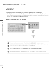
... bearing this phenomenon. the fixed images on the sides of the VCR. 3 Set VCR output switch to 3 or 4 and then tune TV to the same programme number. 4 Insert a video tape into the VCR and press PLAY on the screen. EXTERNAL EQUIPMENT SETUP AV IN 1 COMPONENT IN 2 EXTERNAL EQUIPMENT SETUP 1(DVI) VIDEO AUDIO VIDEO ( ) AUDIO VCR SETUP I If the 4:3 picture format is common to the VCR owner's manual.) 18 I To avoid picture noise (interference), leave...
... bearing this phenomenon. the fixed images on the sides of the VCR. 3 Set VCR output switch to 3 or 4 and then tune TV to the same programme number. 4 Insert a video tape into the VCR and press PLAY on the screen. EXTERNAL EQUIPMENT SETUP AV IN 1 COMPONENT IN 2 EXTERNAL EQUIPMENT SETUP 1(DVI) VIDEO AUDIO VIDEO ( ) AUDIO VCR SETUP I If the 4:3 picture format is common to the VCR owner's manual.) 18 I To avoid picture noise (interference), leave...
Owner's Manual (English)
Page 21
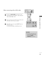
Match the jack colours(Video = yellow, Audio Left = white, and Audio Right = red) 1 2 Insert a video tape into the VCR and press PLAY on the remote control. VIDEO L R S-VIDEO ANT IN OUTPUT ANT OUT SWITCH HDMI/DVI IN 2 1 (DVI) RGB IN RGB (PC) COMPONENT IN VIDEO AUDIO ANTENNA IN DIGITAL AUDIO OUT ! NOTE G If you have a mono VCR, connect the audio cable from the VCR to the VCR owner's manual.) 3 Select A V 1 input source using the INPUT button on the VCR. (Refer to...
Match the jack colours(Video = yellow, Audio Left = white, and Audio Right = red) 1 2 Insert a video tape into the VCR and press PLAY on the remote control. VIDEO L R S-VIDEO ANT IN OUTPUT ANT OUT SWITCH HDMI/DVI IN 2 1 (DVI) RGB IN RGB (PC) COMPONENT IN VIDEO AUDIO ANTENNA IN DIGITAL AUDIO OUT ! NOTE G If you have a mono VCR, connect the audio cable from the VCR to the VCR owner's manual.) 3 Select A V 1 input source using the INPUT button on the VCR. (Refer to...
Owner's Manual (English)
Page 23
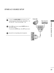
Match the jack colours.(Video = yel- VIDEO L R 3 Operate the corresponding external equipment. If connected to AV IN1 input, select AV1 input source. S-VIDEO 1 VIDEO L/MONO AUDIO R AV IN 2 21 low, Audio Left = white, and Audio Right = red) Camcorder Video Game Set 2 Select AV2 input source using the INPUT button on the remote control. EXTERNAL EQUIPMENT SETUP OTHER A/V SOURCE SETUP 1 Connect the AUDIO/VIDEO jacks between TV and external equipment.
Match the jack colours.(Video = yel- VIDEO L R 3 Operate the corresponding external equipment. If connected to AV IN1 input, select AV1 input source. S-VIDEO 1 VIDEO L/MONO AUDIO R AV IN 2 21 low, Audio Left = white, and Audio Right = red) Camcorder Video Game Set 2 Select AV2 input source using the INPUT button on the remote control. EXTERNAL EQUIPMENT SETUP OTHER A/V SOURCE SETUP 1 Connect the AUDIO/VIDEO jacks between TV and external equipment.
Owner's Manual (English)
Page 24
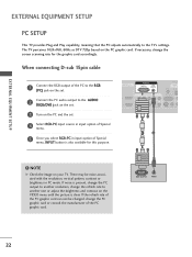
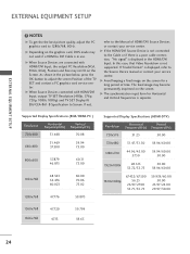
...) COMPONENT IN ANTEN IN REMOTE CONTROL IN DIGITAL AUDIO OUT OPTICA RS-232C IN (CONTROL & SERVICE) VIDEO AUDIO S-VIDEO VIDEO (MON 1 2 ! EXTERNAL EQUIPMENT SETUP EXTERNAL EQUIPMENT SETUP PC SETUP This TV provides Plug and Play capability, meaning that the PC adjusts automatically to the RGB (PC) jack on the set. The TV perceives 1024x768, 60Hz as DTV 720p based on your TV. NOTE G Check the image on the PC graphic card. When connecting D-sub 15pin cable...
...) COMPONENT IN ANTEN IN REMOTE CONTROL IN DIGITAL AUDIO OUT OPTICA RS-232C IN (CONTROL & SERVICE) VIDEO AUDIO S-VIDEO VIDEO (MON 1 2 ! EXTERNAL EQUIPMENT SETUP EXTERNAL EQUIPMENT SETUP PC SETUP This TV provides Plug and Play capability, meaning that the PC adjusts automatically to the RGB (PC) jack on the set. The TV perceives 1024x768, 60Hz as DTV 720p based on your TV. NOTE G Check the image on the PC graphic card. When connecting D-sub 15pin cable...
Owner's Manual (English)
Page 25
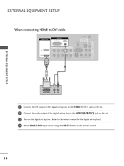
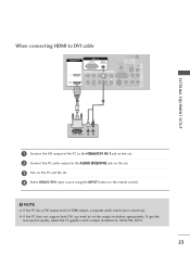
... HDMI output, a separate audio connection is necessary. To get the best picture quality, adjust the PC graphics card's output resolution to set . 4 Select HDMI1/DVI input source using the INPUT button on the PC and the set the output resolution appropriately. When connecting HDMI to DVI cable HDMI/DVI IN 2 1 (DVI) RGB IN RGB (PC) AUDIO (RGB/DVI) COMPONENT IN ANTENNA IN REMOTE CONTROL IN DIGITAL AUDIO OUT OPTICAL VIDEO RS-232C IN (CONTROL & SERVICE) AUDIO VIDEO AUDIO S-VIDEO VIDEO (MONO) AUDIO 1 2 AV IN 1 AV OUT HDMI/DV (DVI) EXTERNAL EQUIPMENT SETUP...
... HDMI output, a separate audio connection is necessary. To get the best picture quality, adjust the PC graphics card's output resolution to set . 4 Select HDMI1/DVI input source using the INPUT button on the PC and the set the output resolution appropriately. When connecting HDMI to DVI cable HDMI/DVI IN 2 1 (DVI) RGB IN RGB (PC) AUDIO (RGB/DVI) COMPONENT IN ANTENNA IN REMOTE CONTROL IN DIGITAL AUDIO OUT OPTICAL VIDEO RS-232C IN (CONTROL & SERVICE) AUDIO VIDEO AUDIO S-VIDEO VIDEO (MONO) AUDIO 1 2 AV IN 1 AV OUT HDMI/DV (DVI) EXTERNAL EQUIPMENT SETUP...
Owner's Manual (English)
Page 26
... TV SET and contact a PC graphics card service center. If "Invalid Format" is displayed, refer to DVI Cable is in use. G The synchronization input form for a long period of time. G If the HDMI/DVI Source Device is displayed in the picture below, press the OK button to Screen. In this case, that Video Resolution is separate. G Avoid keeping a fixed image on the graphics card, DOS mode may not work if a HDMI...
... TV SET and contact a PC graphics card service center. If "Invalid Format" is displayed, refer to DVI Cable is in use. G The synchronization input form for a long period of time. G If the HDMI/DVI Source Device is displayed in the picture below, press the OK button to Screen. In this case, that Video Resolution is separate. G Avoid keeping a fixed image on the graphics card, DOS mode may not work if a HDMI...
Owner's Manual (English)
Page 29
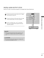
.... 27 VIDEO AUDIO IN REMOTE CONTROL IN DIGITAL AUDIO OUT OPTICAL VIDEO RS-232C IN (CONTROL & SERVICE) 1 AUDIO S-VIDEO VIDEO (MONO) AUDIO 3 Set the "TV Speaker option - CAUTION G Do not look into the optical output port. Off" in the AUDIO menu. AV OUT AV IN 1 EXTERNAL EQUIPMENT SETUP DIGITAL AUDIO OUTPUT SETUP Send the TV's audio to the digi- O DVI) COMPONENT IN 2 2 Connect the other end of an optical cable to the TV DiRgGiBt(aPCl) Audio (Optical) Output port. See the external audio equipment instruction manual for operation. 2 ! RGB IN HDMI/DVI IN 1 Connect one...
.... 27 VIDEO AUDIO IN REMOTE CONTROL IN DIGITAL AUDIO OUT OPTICAL VIDEO RS-232C IN (CONTROL & SERVICE) 1 AUDIO S-VIDEO VIDEO (MONO) AUDIO 3 Set the "TV Speaker option - CAUTION G Do not look into the optical output port. Off" in the AUDIO menu. AV OUT AV IN 1 EXTERNAL EQUIPMENT SETUP DIGITAL AUDIO OUTPUT SETUP Send the TV's audio to the digi- O DVI) COMPONENT IN 2 2 Connect the other end of an optical cable to the TV DiRgGiBt(aPCl) Audio (Optical) Output port. See the external audio equipment instruction manual for operation. 2 ! RGB IN HDMI/DVI IN 1 Connect one...
Owner's Manual (English)
Page 30
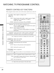
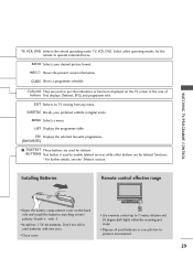
... Control some video cassette recorders or DVD players control buttons ("RECORD" button is not available for DVD player). VOLUME Increase/decrease the sound level. NUMBER button Selects a programme. APM Concurrently, compare with the Dynamic, Standard, Mild, User1 and User2 on the TV. SLEEP Sets the sleep timer. When you toggle this button, the Simplink menu appears at the remote control sensor on the screen. UP/DOWN Q.VIEW Returns to the default settings brightness by changing mode source. INPUT D/A INPUT POWER SIMPLINK BRIGHT MODE TV VCR DVD ! POWER Switches...
... Control some video cassette recorders or DVD players control buttons ("RECORD" button is not available for DVD player). VOLUME Increase/decrease the sound level. NUMBER button Selects a programme. APM Concurrently, compare with the Dynamic, Standard, Mild, User1 and User2 on the TV. SLEEP Sets the sleep timer. When you toggle this button, the Simplink menu appears at the remote control sensor on the screen. UP/DOWN Q.VIEW Returns to the default settings brightness by changing mode source. INPUT D/A INPUT POWER SIMPLINK BRIGHT MODE TV VCR DVD ! POWER Switches...
Owner's Manual (English)
Page 31
.... SUBTITLE Recalls your desired picture format. LIST Displays the programme table. I Install two 1.5V AA batteries. Select other buttons are used to enable teletext services while other operating modes, for teletext. FAV Displays the selected favourite programmes. (FAVOURITE) 1 TELETEXT These buttons are for teletext functions. * For further details, see the 'Teletext' section. I Close cover. INPUT D/A INPUT POWER SIMPLINK BRIGHT MODE TV VCR DVD RATIO TEXT INFO GUIDE I Use a remote control up to TV viewing from any menu. RATIO...
.... SUBTITLE Recalls your desired picture format. LIST Displays the programme table. I Install two 1.5V AA batteries. Select other buttons are used to enable teletext services while other operating modes, for teletext. FAV Displays the selected favourite programmes. (FAVOURITE) 1 TELETEXT These buttons are for teletext functions. * For further details, see the 'Teletext' section. I Close cover. INPUT D/A INPUT POWER SIMPLINK BRIGHT MODE TV VCR DVD RATIO TEXT INFO GUIDE I Use a remote control up to TV viewing from any menu. RATIO...

Owner's Manual (English)
Page 37
... this manual. 1 Press the MENU button and then use D or E button to select the each menu. 2 Press the G button and then use D or E or F or G buttons to display the available menus. SETUP Auto programme Manual programme Programme edit Signal strength Set ID PICTURE PSM Color Temperature XD Advanced Video preset LOCK Lock system Set password Block programme Parental guidance Aux. block AUDIO SSM AVL Balance TV Speaker SPECIAL Input Subtitle Child lock ARC XD demo SIMPLINK TIME Auto clock Manual clock Off time On time Sleep timer Auto sleep...
... this manual. 1 Press the MENU button and then use D or E button to select the each menu. 2 Press the G button and then use D or E or F or G buttons to display the available menus. SETUP Auto programme Manual programme Programme edit Signal strength Set ID PICTURE PSM Color Temperature XD Advanced Video preset LOCK Lock system Set password Block programme Parental guidance Aux. block AUDIO SSM AVL Balance TV Speaker SPECIAL Input Subtitle Child lock ARC XD demo SIMPLINK TIME Auto clock Manual clock Off time On time Sleep timer Auto sleep...
Owner's Manual (English)
Page 38
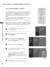
... using automatic or manual modes. WATCHING TV/PROGRAMME CONTROL 1 Press the MENU button and then D or E button to select the SETUP menu. 2 Press the G button and then D or E button to select Auto programme. 3 Press the G button to select Storage from 0 To start G Processing Auto programme... All of service-information will be updated. 26 % 5 channels found Press (OK) to start Programme edit Signal strength Set ID 23 Auto programme G Manual programme Programme edit Signal strength Set...
... using automatic or manual modes. WATCHING TV/PROGRAMME CONTROL 1 Press the MENU button and then D or E button to select the SETUP menu. 2 Press the G button and then D or E button to select Auto programme. 3 Press the G button to select Storage from 0 To start G Processing Auto programme... All of service-information will be updated. 26 % 5 channels found Press (OK) to start Programme edit Signal strength Set ID 23 Auto programme G Manual programme Programme edit Signal strength Set...
Owner's Manual (English)
Page 86
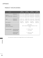
... SPECIFICATIONS MODELS Including stand Dimensions (Width x Height x Depth) Excluding stand Weight including stand excluding stand Power requirement Television System Program Coverage External Antenna Impedance 26LC7D* (26LC7D-AB) 32LC7D* (32LC7D-AB) 37LC7D* (37LC7D-AB) 42LC7D* (42LC7D-AB) 26.6 x 20.9x 8.7 inches 31.8 x 23.9x 9.8 inches 36.5x27.3x11.0inches 40.7x29.5x11.3inches 676.5 x 531.2 x 221.0mm 806.6x606.5x249.0mm 927.0x692.8x280.5mm 1033.4x750.0x287.6mm 26...
... SPECIFICATIONS MODELS Including stand Dimensions (Width x Height x Depth) Excluding stand Weight including stand excluding stand Power requirement Television System Program Coverage External Antenna Impedance 26LC7D* (26LC7D-AB) 32LC7D* (32LC7D-AB) 37LC7D* (37LC7D-AB) 42LC7D* (42LC7D-AB) 26.6 x 20.9x 8.7 inches 31.8 x 23.9x 9.8 inches 36.5x27.3x11.0inches 40.7x29.5x11.3inches 676.5 x 531.2 x 221.0mm 806.6x606.5x249.0mm 927.0x692.8x280.5mm 1033.4x750.0x287.6mm 26...
Owner's Manual (English)
Page 87
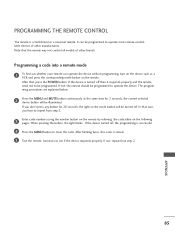
... and the remote need not to be illuminated. After that case, you don't press any button for 2 seconds, the current selected device button will be turned off. If not, repeat from step 2. 3 Enter code numbers using the number button on the remote by referring the code table on the mode button will be programmed. In that , press the POWER button. When pressing the button, the light blinks. PROGRAMMING THE REMOTE CONTROL The remote is stored...
... and the remote need not to be illuminated. After that case, you don't press any button for 2 seconds, the current selected device button will be turned off. If not, repeat from step 2. 3 Enter code numbers using the number button on the remote by referring the code table on the mode button will be programmed. In that , press the POWER button. When pressing the button, the light blinks. PROGRAMMING THE REMOTE CONTROL The remote is stored...


