User Guide
Page 9
Contents 1 Server Board Features 13 Connector and Header Locations 18 Product Codes SE7520BD2, SE7520BD2SCSI, SE7520BD2V 18 Product Codes SE7520BD2SCSID2, SE7520BD2VD2, SE7520BD2SATAD2 20 Configuration Jumpers ...22 Back Panel Connectors...23 Hardware Requirements ...24 Server Chassis ...24 Processor ...24 Memory ...25 2 Hardware Installations and Upgrades 28 Before You Begin ...28 Tools and... Diagnostic Testing 47 Confirming Loading of the Operating System 48 Specific Problems and Corrective Actions 48 Power Light Does Not Light 48 Intel® Server Board SE7520BD2 User Guide ix
Contents 1 Server Board Features 13 Connector and Header Locations 18 Product Codes SE7520BD2, SE7520BD2SCSI, SE7520BD2V 18 Product Codes SE7520BD2SCSID2, SE7520BD2VD2, SE7520BD2SATAD2 20 Configuration Jumpers ...22 Back Panel Connectors...23 Hardware Requirements ...24 Server Chassis ...24 Processor ...24 Memory ...25 2 Hardware Installations and Upgrades 28 Before You Begin ...28 Tools and... Diagnostic Testing 47 Confirming Loading of the Operating System 48 Specific Problems and Corrective Actions 48 Power Light Does Not Light 48 Intel® Server Board SE7520BD2 User Guide ix
User Guide
Page 11
Intel® Server Board SE7520BD2 13 Figure 2. Back Panel Connectors 23 Figure 6. Opening Socket Lever 31 Figure 8. Recovery Boot Jumper 43 Figure 13. Server Board Features 17 Table 3. POST Error..., and SE7520BD2V Connector and Header Locations...19 Figure 3. Installing Memory...29 Figure 7. Replacing the Backup Battery 36 Figure 12. NIC LEDs ...23 Table 5. Contents Figures Figure 1. Configuration Jumper Location 22 Figure 5. Inserting Processor...31 Figure 9. Intel® Server Chassis Supported for each Server Board SE7520BD2 Product Code.. 24 Table 6. ...
Intel® Server Board SE7520BD2 13 Figure 2. Back Panel Connectors 23 Figure 6. Opening Socket Lever 31 Figure 8. Recovery Boot Jumper 43 Figure 13. Server Board Features 17 Table 3. POST Error..., and SE7520BD2V Connector and Header Locations...19 Figure 3. Installing Memory...29 Figure 7. Replacing the Backup Battery 36 Figure 12. NIC LEDs ...23 Table 5. Contents Figures Figure 1. Configuration Jumper Location 22 Figure 5. Inserting Processor...31 Figure 9. Intel® Server Chassis Supported for each Server Board SE7520BD2 Product Code.. 24 Table 6. ...
User Guide
Page 17
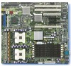
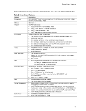
..., and power (not on product codes SE7520BD2V and SE7520BD2VD2) ƒ Custom front panel LCD connectors for additional information. Server Board Features Feature Processors Description Up to two Intel® Xeon™ processors with an FC...SE7520BD2V and SE7520BD2VD2) ƒ Slot 6: PCI-X* 64-bit/133-MHz ƒ Six multi-speed system fan headers. ƒ Two single-speed CPU fan headers. ƒ National Semiconductor* PC87431M controller to provide monitoring, alerting and logging of the server board. Table 2. See Table 1 for use with the Intel® Local Control Panel ƒ Intel...
..., and power (not on product codes SE7520BD2V and SE7520BD2VD2) ƒ Custom front panel LCD connectors for additional information. Server Board Features Feature Processors Description Up to two Intel® Xeon™ processors with an FC...SE7520BD2V and SE7520BD2VD2) ƒ Slot 6: PCI-X* 64-bit/133-MHz ƒ Six multi-speed system fan headers. ƒ Two single-speed CPU fan headers. ƒ National Semiconductor* PC87431M controller to provide monitoring, alerting and logging of the server board. Table 2. See Table 1 for use with the Intel® Local Control Panel ƒ Intel...
User Guide
Page 19
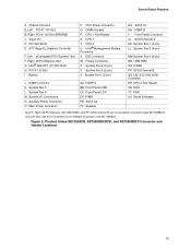
... Codes SE7520BD2, SE7520BD2SCSI, and SE7520BD2V Connector and Header Locations 19 Server Board Features A Chassis Intrusion B, Left PCI-X* 100 Slot B, Right PCI-X 100 Slot (MROMB) C Super I/O D PCI Slot 32/33 E ATI* Rage XL Graphics Controller F, Left x8 (x4speed) PCI-Express* Slot F, Right x8 PCI-Express Slot G Intel®...6 M System I/O Connectors N Auxiliary Power Connector O Main Power Connector AA HSBP A BB Front Panel USB CC Front Panel LCP DD IPMB EE SATA A2 FF Speaker GG SATA A1 HH HSBP B II Front Panel Connector JJ SCSI Channel A KK System Fan 1 (3-pin) LL System Fan 3 (6-pin) MM ...
... Codes SE7520BD2, SE7520BD2SCSI, and SE7520BD2V Connector and Header Locations 19 Server Board Features A Chassis Intrusion B, Left PCI-X* 100 Slot B, Right PCI-X 100 Slot (MROMB) C Super I/O D PCI Slot 32/33 E ATI* Rage XL Graphics Controller F, Left x8 (x4speed) PCI-Express* Slot F, Right x8 PCI-Express Slot G Intel®...6 M System I/O Connectors N Auxiliary Power Connector O Main Power Connector AA HSBP A BB Front Panel USB CC Front Panel LCP DD IPMB EE SATA A2 FF Speaker GG SATA A1 HH HSBP B II Front Panel Connector JJ SCSI Channel A KK System Fan 1 (3-pin) LL System Fan 3 (6-pin) MM ...


