User Guide
Page 3
... who are shipped with the board or that may need, troubleshooting information, and instructions on how to http://support.intel.com/support/motherboards/server/SE7520BD2/. You will also find BIOS error messages and POST code messages. This document provides a brief overview of the ...to update the system. Preface About this chapter for step-bystep instructions and diagrams for installing or replacing components such as the memory, processor, and the battery, among other components you for purchasing and using the utilities that are responsible for troubleshooting, upgrading,...
... who are shipped with the board or that may need, troubleshooting information, and instructions on how to http://support.intel.com/support/motherboards/server/SE7520BD2/. You will also find BIOS error messages and POST code messages. This document provides a brief overview of the ...to update the system. Preface About this chapter for step-bystep instructions and diagrams for installing or replacing components such as the memory, processor, and the battery, among other components you for purchasing and using the utilities that are responsible for troubleshooting, upgrading,...
User Guide
Page 4
... For in-depth technical information about the accessories that have been tested with this product Obtain this document / software Intel® Server Board SE7520BD2 Technical Product Specification Intel® Server Board SE7520BD2 Quick Start User's Guide located in the product box or to install it Accessories or other...drive ƒ Floppy drive/CD-ROM drive/DVD-ROM drive ƒ RAID controller ƒ Operating system For information about which accessories, memory, processors, and third-party hardware have been tested and can be used with your board, look for the server board, check the...
... For in-depth technical information about the accessories that have been tested with this product Obtain this document / software Intel® Server Board SE7520BD2 Technical Product Specification Intel® Server Board SE7520BD2 Quick Start User's Guide located in the product box or to install it Accessories or other...drive ƒ Floppy drive/CD-ROM drive/DVD-ROM drive ƒ RAID controller ƒ Operating system For information about which accessories, memory, processors, and third-party hardware have been tested and can be used with your board, look for the server board, check the...
User Guide
Page 5
...your system falls within the allowed power budget For software to manage your Intel® Server For firmware, BIOS updates, and drivers Supported Processor List Tested Memory List Power Budget Tool Intel® Server Management Software Download Finder To obtain the documents or software... mentioned in the above table and for the latest product technical information, please go to: http://support.intel.com/support/motherboards/server/SE7520BD2 Safety Information ...
...your system falls within the allowed power budget For software to manage your Intel® Server For firmware, BIOS updates, and drivers Supported Processor List Tested Memory List Power Budget Tool Intel® Server Management Software Download Finder To obtain the documents or software... mentioned in the above table and for the latest product technical information, please go to: http://support.intel.com/support/motherboards/server/SE7520BD2 Safety Information ...
User Guide
Page 9
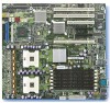
Contents 1 Server Board Features 13 Connector and Header Locations 18 Product Codes SE7520BD2, SE7520BD2SCSI, SE7520BD2V 18 Product Codes SE7520BD2SCSID2, SE7520BD2VD2, SE7520BD2SATAD2 20 Configuration Jumpers ...22 Back Panel Connectors...23 Hardware Requirements ...24 Server Chassis ...24 Processor ...24 Memory ...25 2 Hardware Installations and Upgrades 28 Before You Begin ...28 Tools and ... Diagnostic Testing 47 Confirming Loading of the Operating System 48 Specific Problems and Corrective Actions 48 Power Light Does Not Light 48 Intel® Server Board SE7520BD2 User Guide ix
Contents 1 Server Board Features 13 Connector and Header Locations 18 Product Codes SE7520BD2, SE7520BD2SCSI, SE7520BD2V 18 Product Codes SE7520BD2SCSID2, SE7520BD2VD2, SE7520BD2SATAD2 20 Configuration Jumpers ...22 Back Panel Connectors...23 Hardware Requirements ...24 Server Chassis ...24 Processor ...24 Memory ...25 2 Hardware Installations and Upgrades 28 Before You Begin ...28 Tools and ... Diagnostic Testing 47 Confirming Loading of the Operating System 48 Specific Problems and Corrective Actions 48 Power Light Does Not Light 48 Intel® Server Board SE7520BD2 User Guide ix
User Guide
Page 11
Contents Figures Figure 1. Configuration Jumper Location 22 Figure 5. Installing Memory...29 Figure 7. POST Error Beep Codes 54 Table 9. Intel® Server Board SE7520BD2 13 Figure 2. Product Codes SE7520BD2, SE7520BD2SCSI, and SE7520BD2V Connector and Header Locations...19 Figure 3. Inserting Processor... 8. Replacing the Backup Battery 36 Figure 12. Recovery Boot Jumper 43 Figure 13. Intel® Server Chassis Supported for each Server Board SE7520BD2 Product Code.. 24 Table 6. Product Codes SE7520BD2SCSID2, SE7520BD2VD2, and SE7520BD2SATAD2 Connector and Header...
Contents Figures Figure 1. Configuration Jumper Location 22 Figure 5. Installing Memory...29 Figure 7. POST Error Beep Codes 54 Table 9. Intel® Server Board SE7520BD2 13 Figure 2. Product Codes SE7520BD2, SE7520BD2SCSI, and SE7520BD2V Connector and Header Locations...19 Figure 3. Inserting Processor... 8. Replacing the Backup Battery 36 Figure 12. Recovery Boot Jumper 43 Figure 13. Intel® Server Chassis Supported for each Server Board SE7520BD2 Product Code.. 24 Table 6. Product Codes SE7520BD2SCSID2, SE7520BD2VD2, and SE7520BD2SATAD2 Connector and Header...
User Guide
Page 14
... board - Server Board Features Table 1. One IDE connector supporting two ATA/100 IDE channels. Four: - Server Board Varieties Product Code Memory PCI SCSI Product code SE7520BD2 Product code SE7520BD2SATAD2 Six DIMM sockets DDR 266/333 72-bit, 184-pin DIMMs Supported DIMM sizes: 256 MB, 512 MB, 1 GB..., 2 GB, 4 GB 24 GB Maximum (when 4 GB DIMMs are available) Dual channel architecture Memory Mirroring Memory Sparing Eight DIMM sockets ...
... board - Server Board Features Table 1. One IDE connector supporting two ATA/100 IDE channels. Four: - Server Board Varieties Product Code Memory PCI SCSI Product code SE7520BD2 Product code SE7520BD2SATAD2 Six DIMM sockets DDR 266/333 72-bit, 184-pin DIMMs Supported DIMM sizes: 256 MB, 512 MB, 1 GB..., 2 GB, 4 GB 24 GB Maximum (when 4 GB DIMMs are available) Dual channel architecture Memory Mirroring Memory Sparing Eight DIMM sockets ...
User Guide
Page 15
...333 72-bit, 184-pin DIMMs Supported DIMM sizes: 256MB, 512MB, 1GB, 2GB, 4GB 24 GB Maximum (when 4GB DIMMs are available) Dual channel architecture Memory Mirroring Memory Sparing Eight DIMM sockets DDR2-400 240-pin ECC Registered DIMMs Supported DIMM sizes: 256 MB, 512 MB, 1 GB, 2 GB 16 GB Maximum Dual... channel architecture Memory Mirroring Memory Sparing One PCI Express* x8 One PCI Express x4 One PCI-X* 133MHz Two PCI-X 100MHz One PCI 32-bit / 33MHz 5V Two Ultra320/LVD channels...
...333 72-bit, 184-pin DIMMs Supported DIMM sizes: 256MB, 512MB, 1GB, 2GB, 4GB 24 GB Maximum (when 4GB DIMMs are available) Dual channel architecture Memory Mirroring Memory Sparing Eight DIMM sockets DDR2-400 240-pin ECC Registered DIMMs Supported DIMM sizes: 256 MB, 512 MB, 1 GB, 2 GB 16 GB Maximum Dual... channel architecture Memory Mirroring Memory Sparing One PCI Express* x8 One PCI Express x4 One PCI-X* 133MHz Two PCI-X 100MHz One PCI 32-bit / 33MHz 5V Two Ultra320/LVD channels...
User Guide
Page 16
...72-bit, 184-pin DIMMs Supported DIMM sizes: 256MB, 512MB, 1GB, 2GB, 4GB 24 GB Maximum (when 4 GB DIMMs are available) Dual channel architecture Memory Mirroring Memory Sparing Eight DIMM sockets DDR2-400 240-pin ECC Registered DIMMs Supported DIMM sizes: 256 MB, 512 MB, 1 GB, 2 GB 16 GB Maximum Dual ...channel architecture Memory Mirroring Memory Sparing One PCI Express x4 One PCI-X 133MHz Two PCI-X 100MHz One PCI 32-bit / 33MHz 5V One Ultra320/LVD channel via either the LSI...
...72-bit, 184-pin DIMMs Supported DIMM sizes: 256MB, 512MB, 1GB, 2GB, 4GB 24 GB Maximum (when 4 GB DIMMs are available) Dual channel architecture Memory Mirroring Memory Sparing Eight DIMM sockets DDR2-400 240-pin ECC Registered DIMMs Supported DIMM sizes: 256 MB, 512 MB, 1 GB, 2 GB 16 GB Maximum Dual ...channel architecture Memory Mirroring Memory Sparing One PCI Express x4 One PCI-X 133MHz Two PCI-X 100MHz One PCI 32-bit / 33MHz 5V One Ultra320/LVD channel via either the LSI...
User Guide
Page 17
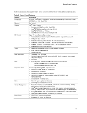
... and an 800-MHz Front Side Bus (FSB) Memory Chipset See Table 1 Intel® E7520 chipset: ƒ Supports 800 MHz Front Side Bus (FSB) ƒ Intel® E7520 Memory Controller Hub (MCH) ƒ Intel® 6700PXH 64-bit PCI Hub ƒ Intel® 82801ER I/O Controller Hub5 (ICH-5R) ... inches 17 Server Board Features Table 2 summarizes the major features of critical sensor information. ƒ Intel® Light-Guided Diagnostics on critical FRU devices, such as processors, memory, and power (not on product codes SE7520BD2V and SE7520BD2VD2) ƒ Custom front panel LCD connectors for...
... and an 800-MHz Front Side Bus (FSB) Memory Chipset See Table 1 Intel® E7520 chipset: ƒ Supports 800 MHz Front Side Bus (FSB) ƒ Intel® E7520 Memory Controller Hub (MCH) ƒ Intel® 6700PXH 64-bit PCI Hub ƒ Intel® 82801ER I/O Controller Hub5 (ICH-5R) ... inches 17 Server Board Features Table 2 summarizes the major features of critical sensor information. ƒ Intel® Light-Guided Diagnostics on critical FRU devices, such as processors, memory, and power (not on product codes SE7520BD2V and SE7520BD2VD2) ƒ Custom front panel LCD connectors for...
User Guide
Page 25
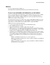
... of DIMMs across two channels. The maximum allowed usable memory is closest to be identical within each bank. Product Codes SE7520BD2, SE7520BD2SCSI, and SE7520BD2V Product codes SE7520BD2, SE7520BD2SCSI, and SE7520BD2V include three banks of supported memory DIMMs, see: http://support.intel.com/support/motherboards/server/se7520bd2/sb/CS-013543.htm. Except for dual-channel interleave, providing...
... of DIMMs across two channels. The maximum allowed usable memory is closest to be identical within each bank. Product Codes SE7520BD2, SE7520BD2SCSI, and SE7520BD2V Product codes SE7520BD2, SE7520BD2SCSI, and SE7520BD2V include three banks of supported memory DIMMs, see: http://support.intel.com/support/motherboards/server/se7520bd2/sb/CS-013543.htm. Except for dual-channel interleave, providing...
User Guide
Page 26
... providing optimum performance, a minimum of two DIMMs should be used. In a mirrored system, the maximum usable memory is available from the mirrored DIMM. Server Board Features Intel® Server Boards SE7520BD2SCSID2, SE7520BD2SATAD2, and SE7520BD2VD2 Product codes SE7520BD2SCSID2, SE7520BD2SATAD2, and SE7520BD2VD2 include four banks of DIMMs... copy of the data is one time. Channel A consists of DIMMs 1B, 2B, 3B, and 4B. Memory Mirroring and Memory On-line Sparing The Intel® E7520 chipset includes hardware that up to four DIMMs are actively in addition to DIMM 1A and DIMM ...
... providing optimum performance, a minimum of two DIMMs should be used. In a mirrored system, the maximum usable memory is available from the mirrored DIMM. Server Board Features Intel® Server Boards SE7520BD2SCSID2, SE7520BD2SATAD2, and SE7520BD2VD2 Product codes SE7520BD2SCSID2, SE7520BD2SATAD2, and SE7520BD2VD2 include four banks of DIMMs... copy of the data is one time. Channel A consists of DIMMs 1B, 2B, 3B, and 4B. Memory Mirroring and Memory On-line Sparing The Intel® E7520 chipset includes hardware that up to four DIMMs are actively in addition to DIMM 1A and DIMM ...
User Guide
Page 27
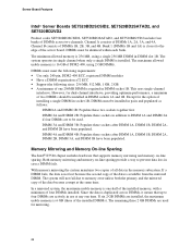
...131; For the Intel Entry Server Chassis SC5275-E, a minimum 600W power supply is removed from service and the spare DIMM takes its place. Use the power budget tool to determine the minimum power supply for your system, based on -line sparing is used as the memory spare. For a... in that channel. For additional information, see "Additional Information and Software". 27 When memory on all of the failing DIMM is copied to the power budget utility, see the Intel® Server Board SE7520BD2 Technical Product Specification. If a DIMM begins to fail, the content of the data ...
...131; For the Intel Entry Server Chassis SC5275-E, a minimum 600W power supply is removed from service and the spare DIMM takes its place. Use the power budget tool to determine the minimum power supply for your system, based on -line sparing is used as the memory spare. For a... in that channel. For additional information, see "Additional Information and Software". 27 When memory on all of the failing DIMM is copied to the power budget utility, see the Intel® Server Board SE7520BD2 Technical Product Specification. If a DIMM begins to fail, the content of the data ...

User Guide
Page 28
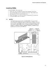
... Anti-static wrist strap and conductive foam pad (recommended) Installing and Removing Memory The silkscreen on the board for this manual show product code SE7520BD2. See "Additional Information and Software" for a link to the list of...memory requirements and options. 2 Hardware Installations and Upgrades Before You Begin Before working with your server product, pay close attention to the "Safety Information" at the beginning of this manual. ✏ NOTES Most diagrams in this server board. Where necessary to complete a procedure, differences are noted. Intel® Server Board SE7520BD2...
... Anti-static wrist strap and conductive foam pad (recommended) Installing and Removing Memory The silkscreen on the board for this manual show product code SE7520BD2. See "Additional Information and Software" for a link to the list of...memory requirements and options. 2 Hardware Installations and Upgrades Before You Begin Before working with your server product, pay close attention to the "Safety Information" at the beginning of this manual. ✏ NOTES Most diagrams in this server board. Where necessary to complete a procedure, differences are noted. Intel® Server Board SE7520BD2...
User Guide
Page 29
..., the eight DIMM sockets are using a Server Board SE7520BD2 that supports DDR2 memory DIMMs, your server board will have eight DIMM sockets instead of this book. 2. See your memory with DIMM 1B. See Figure 6. ✏ NOTES The diagram below . Installing Memory TP00722 29 Turn off the server. 3. Disconnect the ... DIMM sockets. From left to the server. Observe the safety and ESD precautions at the beginning of the six pictured below shows product code SE7520BD2. If you are numbered DIMM 4A, DIMM 4B, DIMM 3A, DIMM3B, DIMM2A, DIMM2B, DIMM1A, DIMM1B. DIMM 2A DIMM 3B DIMM 3A...
..., the eight DIMM sockets are using a Server Board SE7520BD2 that supports DDR2 memory DIMMs, your server board will have eight DIMM sockets instead of this book. 2. See your memory with DIMM 1B. See Figure 6. ✏ NOTES The diagram below . Installing Memory TP00722 29 Turn off the server. 3. Disconnect the ... DIMM sockets. From left to the server. Observe the safety and ESD precautions at the beginning of the six pictured below shows product code SE7520BD2. If you are numbered DIMM 4A, DIMM 4B, DIMM 3A, DIMM3B, DIMM2A, DIMM2B, DIMM1A, DIMM1B. DIMM 2A DIMM 3B DIMM 3A...
User Guide
Page 37
...Starting Setup You can enter and start BIOS Setup under several conditions: ƒ When you turn on the server, after POST completes the memory test ƒ When you have moved the CMOS jumper on clearing the CMOS, see this condition, the BIOS will load default values for ...Setup Utility This section describes the BIOS Setup Utility options, which is associated with or without an operating system present. See the Intel® Server Board SE7520BD2 Technical Product Specification for any reason, the feature's value field is inaccessible. Except for those features that are not able to ...
...Starting Setup You can enter and start BIOS Setup under several conditions: ƒ When you turn on the server, after POST completes the memory test ƒ When you have moved the CMOS jumper on clearing the CMOS, see this condition, the BIOS will load default values for ...Setup Utility This section describes the BIOS Setup Utility options, which is associated with or without an operating system present. See the Intel® Server Board SE7520BD2 Technical Product Specification for any reason, the feature's value field is inaccessible. Except for those features that are not able to ...
User Guide
Page 39
... Setup Utility ƒ The System BIOS Preparing for the utilty Recording the Current BIOS Settings 1. Review any release notes in flash memory. The BIOS upgrade utility allows you check the Intel website Download Finder for a link to configure your hard drive. The SUP contains the BIOS, FRU/SDR and HSC firmware all...
... Setup Utility ƒ The System BIOS Preparing for the utilty Recording the Current BIOS Settings 1. Review any release notes in flash memory. The BIOS upgrade utility allows you check the Intel website Download Finder for a link to configure your hard drive. The SUP contains the BIOS, FRU/SDR and HSC firmware all...
User Guide
Page 40
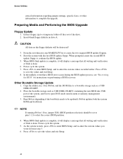
Preparing Media and Performing the BIOS Upgrade Floppy Update 1. Extract floppy.zip to pure DOS mode (non hi-mem or memory management environment). 3. Power cycle the system. 7. Place the bootable storage such as a USB DISK-ON-KEY. 2. fbb.bat updates both the system ROM and bootblock. &#...
Preparing Media and Performing the BIOS Upgrade Floppy Update 1. Extract floppy.zip to pure DOS mode (non hi-mem or memory management environment). 3. Power cycle the system. 7. Place the bootable storage such as a USB DISK-ON-KEY. 2. fbb.bat updates both the system ROM and bootblock. &#...
User Guide
Page 46
... for example, two add-in the proper location and not touching any issue, first ensure you are using the system. Clear system memory, restart POST, and reload the operating system. Check the AC cable(s) on the back of the following Initial System Installation Problems that...board correct? ‰ Are all peripherals. If applicable, ensure that there are usually caused by an incorrect installation or configuration. Intel® Server Board SE7520BD2 User Guide 46 4 Troubleshooting This chapter helps you identify and solve problems that might occur while you are using the latest ...
... for example, two add-in the proper location and not touching any issue, first ensure you are using the system. Clear system memory, restart POST, and reload the operating system. Check the AC cable(s) on the back of the following Initial System Installation Problems that...board correct? ‰ Are all peripherals. If applicable, ensure that there are usually caused by an incorrect installation or configuration. Intel® Server Board SE7520BD2 User Guide 46 4 Troubleshooting This chapter helps you identify and solve problems that might occur while you are using the latest ...
User Guide
Page 47
... two thirds of their maximum ranges (see "Power Light Does Not Light". 47 Turn on the video monitor. Turn on the system. Check the tested memory, and chassis lists, as well as the supported hardware and operating system list. CAUTION Turn off devices before disconnecting cables: Before disconnecting any peripheral cables...
... two thirds of their maximum ranges (see "Power Light Does Not Light". 47 Turn on the video monitor. Turn on the system. Check the tested memory, and chassis lists, as well as the supported hardware and operating system list. CAUTION Turn off devices before disconnecting cables: Before disconnecting any peripheral cables...
User Guide
Page 49
... your service representative. 5. If successful, add the cards back in one at a time with a reboot between each addition. ‰ Make sure the memory DIMMs comply with the system requirements. ‰ Make sure the processor(s) have failed. If successful, add the cards back in one at a time with... the video controller board is useful for your service representative or authorized dealer for changes to the system requirements. ‰ Carefully remove the memory DIMMs and re-seat them . ‰ Make sure the chassis standoffs are using the on the bottom of the server board and cause...
... your service representative. 5. If successful, add the cards back in one at a time with a reboot between each addition. ‰ Make sure the memory DIMMs comply with the system requirements. ‰ Make sure the processor(s) have failed. If successful, add the cards back in one at a time with... the video controller board is useful for your service representative or authorized dealer for changes to the system requirements. ‰ Carefully remove the memory DIMMs and re-seat them . ‰ Make sure the chassis standoffs are using the on the bottom of the server board and cause...


