User Guide
Page 9
Contents 1 Server Board Features 13 Connector and Header Locations 18 Product Codes SE7520BD2, SE7520BD2SCSI, SE7520BD2V 18 Product Codes SE7520BD2SCSID2, SE7520BD2VD2, SE7520BD2SATAD2 20 Configuration Jumpers ...22 Back Panel Connectors...23 Hardware Requirements ...24 Server Chassis ...24 Processor ...24 Memory ...25 2 Hardware Installations and Upgrades 28 Before You Begin ...28 Tools and ... Diagnostic Testing 47 Confirming Loading of the Operating System 48 Specific Problems and Corrective Actions 48 Power Light Does Not Light 48 Intel® Server Board SE7520BD2 User Guide ix
Contents 1 Server Board Features 13 Connector and Header Locations 18 Product Codes SE7520BD2, SE7520BD2SCSI, SE7520BD2V 18 Product Codes SE7520BD2SCSID2, SE7520BD2VD2, SE7520BD2SATAD2 20 Configuration Jumpers ...22 Back Panel Connectors...23 Hardware Requirements ...24 Server Chassis ...24 Processor ...24 Memory ...25 2 Hardware Installations and Upgrades 28 Before You Begin ...28 Tools and ... Diagnostic Testing 47 Confirming Loading of the Operating System 48 Specific Problems and Corrective Actions 48 Power Light Does Not Light 48 Intel® Server Board SE7520BD2 User Guide ix
User Guide
Page 11
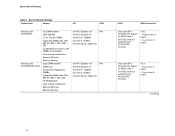
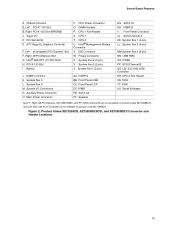
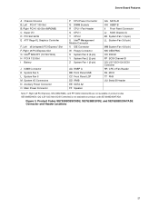
... 14. Server Board Varieties 14 Table 2. POST Error Beep Codes 54 Table 9. Intel® Server Board SE7520BD2 13 Figure 2. Product Codes SE7520BD2, SE7520BD2SCSI, and SE7520BD2V Connector and Header Locations...19 Figure 3. Opening Socket Lever 31 Figure 8. NIC LEDs ......Table 1. Server Board Features 17 Table 3. Intel® Server Chassis Supported for each Server Board SE7520BD2 Product Code.. 24 Table 6. Contents Figures Figure 1. Product Codes SE7520BD2SCSID2, SE7520BD2VD2, and SE7520BD2SATAD2 Connector and Header Locations 21 Figure 4. Inserting Processor......
... 14. Server Board Varieties 14 Table 2. POST Error Beep Codes 54 Table 9. Intel® Server Board SE7520BD2 13 Figure 2. Product Codes SE7520BD2, SE7520BD2SCSI, and SE7520BD2V Connector and Header Locations...19 Figure 3. Opening Socket Lever 31 Figure 8. NIC LEDs ......Table 1. Server Board Features 17 Table 3. Intel® Server Chassis Supported for each Server Board SE7520BD2 Product Code.. 24 Table 6. Contents Figures Figure 1. Product Codes SE7520BD2SCSID2, SE7520BD2VD2, and SE7520BD2SATAD2 Connector and Header Locations 21 Figure 4. Inserting Processor......
User Guide
Page 14
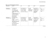
... Features Table 1. Five: - Two at rear of board - Two at front of board Continued 14 Server Board Varieties Product Code Memory PCI SCSI Product code SE7520BD2 Product code SE7520BD2SATAD2 Six DIMM sockets DDR 266/333 72-bit, 184-pin DIMMs Supported DIMM sizes: 256 MB, 512 MB, 1 GB, 2 GB, 4 GB 24... Dual serial ATA channels with support for RAID 0 and 1. Two at front of board Dual serial ATA channels with support for RAID 0 and 1. One IDE connector supporting two ATA/100 IDE channels. One IDE...
... Features Table 1. Five: - Two at rear of board - Two at front of board Continued 14 Server Board Varieties Product Code Memory PCI SCSI Product code SE7520BD2 Product code SE7520BD2SATAD2 Six DIMM sockets DDR 266/333 72-bit, 184-pin DIMMs Supported DIMM sizes: 256 MB, 512 MB, 1 GB, 2 GB, 4 GB 24... Dual serial ATA channels with support for RAID 0 and 1. Two at front of board Dual serial ATA channels with support for RAID 0 and 1. One IDE connector supporting two ATA/100 IDE channels. One IDE...
User Guide
Page 15
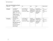
Two at rear of board - One IDE connector supporting two ATA/100 IDE channels. Five: - Two at rear of board - Server Board Features Table 1. Three at front of board One PCI Express* x8 ... 32-bit / 33MHz 5V Two Ultra320/LVD channels via the LSI* 53C1030 SCSI controller Dual serial ATA channels with support for RAID 0 and 1. One IDE connector supporting two ATA/100 IDE channels. Server Board Varieties (continued) Product Code Memory PCI SCSI SATA USB Connections Product code SE7520BD2SCSI Product code SE7520BD2SCSID2 Six...
Two at rear of board - One IDE connector supporting two ATA/100 IDE channels. Five: - Two at rear of board - Server Board Features Table 1. Three at front of board One PCI Express* x8 ... 32-bit / 33MHz 5V Two Ultra320/LVD channels via the LSI* 53C1030 SCSI controller Dual serial ATA channels with support for RAID 0 and 1. One IDE connector supporting two ATA/100 IDE channels. Server Board Varieties (continued) Product Code Memory PCI SCSI SATA USB Connections Product code SE7520BD2SCSI Product code SE7520BD2SCSID2 Six...
User Guide
Page 16
Four: - One IDE connector supporting two ATA/100 IDE channels. Two at rear of board 16 Server Board Features Table 1. Server Board Varieties (continued) Product Code Memory PCI SCSI ... One Ultra320/LVD channel via either the LSI 53C1020 or LSI 53C1020A SCSI controller Dual serial ATA channels with support for RAID 0 and 1. One IDE connector supporting two ATA/100 IDE channels.
Four: - One IDE connector supporting two ATA/100 IDE channels. Two at rear of board 16 Server Board Features Table 1. Server Board Varieties (continued) Product Code Memory PCI SCSI ... One Ultra320/LVD channel via either the LSI 53C1020 or LSI 53C1020A SCSI controller Dual serial ATA channels with support for RAID 0 and 1. One IDE connector supporting two ATA/100 IDE channels.
User Guide
Page 17
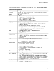
...and integrated striping) ƒ See Table 1 ƒ Dual integrated 10/100/1000 MB on-board Ethernet connectors One Marvell* 88E8050 10/100/1000 LAN One Intel® 82541PI 10/100/1000 LAN Expansion Slots Fans Server Management Form Factor Six full-length, full-height...x8 (not on product codes SE7520BD2V and SE7520BD2VD2) ƒ Custom front panel LCD connectors for additional information. Table 2. Server Board Features Table 2 summarizes the major features of critical sensor information. ƒ Intel® Light-Guided Diagnostics on critical FRU devices, such as processors, memory, and...
...and integrated striping) ƒ See Table 1 ƒ Dual integrated 10/100/1000 MB on-board Ethernet connectors One Marvell* 88E8050 10/100/1000 LAN One Intel® 82541PI 10/100/1000 LAN Expansion Slots Fans Server Management Form Factor Six full-length, full-height...x8 (not on product codes SE7520BD2V and SE7520BD2VD2) ƒ Custom front panel LCD connectors for additional information. Table 2. Server Board Features Table 2 summarizes the major features of critical sensor information. ƒ Intel® Light-Guided Diagnostics on critical FRU devices, such as processors, memory, and...
User Guide
Page 18
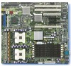
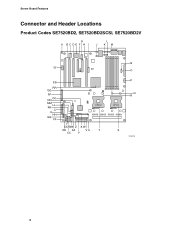
Server Board Features Connector and Header Locations Product Codes SE7520BD2, SE7520BD2SCSI, SE7520BD2V G A BCDE F H I L J KM TT SS RR QQ PP NN OO MM LL KK JJ II HH GG FF CPU 2 DD BB Z X W EE AA VU T CC Y N O P Q R CPU 1 S TP00718 18
Server Board Features Connector and Header Locations Product Codes SE7520BD2, SE7520BD2SCSI, SE7520BD2V G A BCDE F H I L J KM TT SS RR QQ PP NN OO MM LL KK JJ II HH GG FF CPU 2 DD BB Z X W EE AA VU T CC Y N O P Q R CPU 1 S TP00718 18
User Guide
Page 19
Product Codes SE7520BD2, SE7520BD2SCSI, and SE7520BD2V Connector and Header Locations 19 QQ (LSI* 53C1030 SCSI Controller) is not available on product codes SE7520BD2V. Figure 2. Server Board ...PCI-X 133 Slot I Battery P CPU Power Connector Q DIMM Sockets R CPU 1 Fan Header S CPU 1 T CPU 2 U Intel® Management Module Connector V IDE Connector W Floppy Connector X System Fan 2 (3-pin) Y System Fan 2 (2-pin) Z System Fan 1 (2-pin) J ICMB Connector K System Fan 5 L System Fan 6 M System I/O Connectors N Auxiliary Power Connector O Main Power Connector AA HSBP A BB Front Panel USB CC ...
Product Codes SE7520BD2, SE7520BD2SCSI, and SE7520BD2V Connector and Header Locations 19 QQ (LSI* 53C1030 SCSI Controller) is not available on product codes SE7520BD2V. Figure 2. Server Board ...PCI-X 133 Slot I Battery P CPU Power Connector Q DIMM Sockets R CPU 1 Fan Header S CPU 1 T CPU 2 U Intel® Management Module Connector V IDE Connector W Floppy Connector X System Fan 2 (3-pin) Y System Fan 2 (2-pin) Z System Fan 1 (2-pin) J ICMB Connector K System Fan 5 L System Fan 6 M System I/O Connectors N Auxiliary Power Connector O Main Power Connector AA HSBP A BB Front Panel USB CC ...
User Guide
Page 21
... (x4speed) PCI-Express* Slot F, Right x8 PCI-Express Slot G Intel® 82541P1 (10/100/1000) H PCI-X 133 Slot I Battery J ICMB Connector K System Fan 5 L System Fan 6 M System I/O Connectors N Auxiliary Power Connector O Main Power Connector P CPU Power Connector Q DIMM Sockets R CPU 1 Fan Header S CPU 1 T CPU 2 U Intel® Management Module Connector V IDE Connector W Floppy Connector X System Fan 2 (3-pin) Y System Fan 2 (2-pin) Z System Fan...
... (x4speed) PCI-Express* Slot F, Right x8 PCI-Express Slot G Intel® 82541P1 (10/100/1000) H PCI-X 133 Slot I Battery J ICMB Connector K System Fan 5 L System Fan 6 M System I/O Connectors N Auxiliary Power Connector O Main Power Connector P CPU Power Connector Q DIMM Sockets R CPU 1 Fan Header S CPU 1 T CPU 2 U Intel® Management Module Connector V IDE Connector W Floppy Connector X System Fan 2 (3-pin) Y System Fan 2 (2-pin) Z System Fan...
User Guide
Page 23
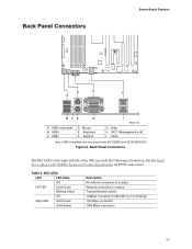
Table 4. See the Intel® Server Board SE7520BD2 Technical Product Specification for POST code errors. NIC LEDs LED LED State Off Left LED Solid Green Blinking Green Off Right LED Solid Green Solid ... Board Features D F H A B CE G A USB3 (see note)* B USB2 C USB1 D Mouse E Keyboard F Serial A I TP00719 G Video H NIC1 (Management port) I NIC2 Note: USB3 is on product codes SE7520BD2 and SE7520BD2SCSI Figure 5. Back Panel Connectors The NIC LEDs at the right and left LED is available only on or blinking) 100 Mbps connection 1000 Mbps connection 23
Table 4. See the Intel® Server Board SE7520BD2 Technical Product Specification for POST code errors. NIC LEDs LED LED State Off Left LED Solid Green Blinking Green Off Right LED Solid Green Solid ... Board Features D F H A B CE G A USB3 (see note)* B USB2 C USB1 D Mouse E Keyboard F Serial A I TP00719 G Video H NIC1 (Management port) I NIC2 Note: USB3 is on product codes SE7520BD2 and SE7520BD2SCSI Figure 5. Back Panel Connectors The NIC LEDs at the right and left LED is available only on or blinking) 100 Mbps connection 1000 Mbps connection 23
User Guide
Page 49
...(s) have been populated according to take effect. 4. If you are installed only below mounting holes. If successful, add the cards back in the server board connector. 3.
...(s) have been populated according to take effect. 4. If you are installed only below mounting holes. If successful, add the cards back in the server board connector. 3.
User Guide
Page 50
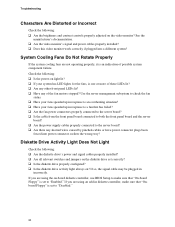
... more of these LEDs lit? ‰ Are any other front panel LEDs lit? ‰ Have any shorted wires caused by pinched-cables or have power connector plugs been forced into a different system? If you are using an add-in diskette controller, make sure that "On-board Floppy" is set to "Disabled... contrast controls properly adjusted on light lit? ‰ If your fans speeded up in response to a fan that has failed? ‰ Are the fan power connectors properly connected to the server board? ‰ Is the cable from the front panel board connected to both the front panel board and the server...
... more of these LEDs lit? ‰ Are any other front panel LEDs lit? ‰ Have any shorted wires caused by pinched-cables or have power connector plugs been forced into a different system? If you are using an add-in diskette controller, make sure that "On-board Floppy" is set to "Disabled... contrast controls properly adjusted on light lit? ‰ If your fans speeded up in response to a fan that has failed? ‰ Are the fan power connectors properly connected to the server board? ‰ Is the cable from the front panel board connected to both the front panel board and the server...
User Guide
Page 51
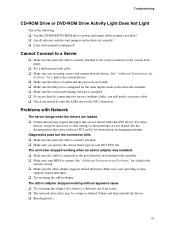
... driver files may require interrupts that are using correct and current network drivers. See "Additional Information and Software" for a link to the correct connector at the system back panel. ‰ Try a different network cable. ‰ Make sure you specify the correct frame type in adapter stopped... supports shared interrupts. ‰ Try reseating the add-in adapter was installed. ‰ Make sure the cable is connected to the NIC connectors. Diagnostics pass but the connection fails. ‰ Make sure the network cable is current. Make sure your PCI card(s) for the same ...
... driver files may require interrupts that are using correct and current network drivers. See "Additional Information and Software" for a link to the correct connector at the system back panel. ‰ Try a different network cable. ‰ Make sure you specify the correct frame type in adapter stopped... supports shared interrupts. ‰ Try reseating the add-in adapter was installed. ‰ Make sure the cable is connected to the NIC connectors. Diagnostics pass but the connection fails. ‰ Make sure the network cable is current. Make sure your PCI card(s) for the same ...


