User Guide
Page 3
... diagrams to http://support.intel.com/support/motherboards/server/SE7520BD2/. Use this chapter, you will find BIOS error messages and POST code messages. In this chapter for step-bystep instructions and diagrams for installing or replacing components such as the memory, processor, and the battery, ...manual is available in this server board. For the latest version of these products. ✏ NOTES Most diagrams in the Intel® Server Board SE7520BD2 Technical Product Specification. In this manual, refer to help you will also find a list of the server board features, photos...
... diagrams to http://support.intel.com/support/motherboards/server/SE7520BD2/. Use this chapter, you will find BIOS error messages and POST code messages. In this chapter for step-bystep instructions and diagrams for installing or replacing components such as the memory, processor, and the battery, ...manual is available in this server board. For the latest version of these products. ✏ NOTES Most diagrams in the Intel® Server Board SE7520BD2 Technical Product Specification. In this manual, refer to help you will also find a list of the server board features, photos...
User Guide
Page 4
... drive ƒ RAID controller ƒ Operating system For information about which accessories, memory, processors, and third-party hardware have been tested with this product Obtain this document / software Intel® Server Board SE7520BD2 Technical Product Specification Intel® Server Board SE7520BD2 Quick Start User's Guide located in -depth technical information about the accessories that have...
... drive ƒ RAID controller ƒ Operating system For information about which accessories, memory, processors, and third-party hardware have been tested with this product Obtain this document / software Intel® Server Board SE7520BD2 Technical Product Specification Intel® Server Board SE7520BD2 Quick Start User's Guide located in -depth technical information about the accessories that have...
User Guide
Page 5
...the region(s) in the above table and for the latest product technical information, please go to: http://support.intel.com/support/motherboards/server/SE7520BD2 Safety Information Emissions Disclaimer To ensure EMC compliance with your local regional rules and regulations, the final configuration of... be installed in this server board. You must adhere to manage your Intel® Server For firmware, BIOS updates, and drivers Supported Processor List Tested Memory List Power Budget Tool Intel® Server Management Software Download Finder To obtain the documents or software mentioned...
...the region(s) in the above table and for the latest product technical information, please go to: http://support.intel.com/support/motherboards/server/SE7520BD2 Safety Information Emissions Disclaimer To ensure EMC compliance with your local regional rules and regulations, the final configuration of... be installed in this server board. You must adhere to manage your Intel® Server For firmware, BIOS updates, and drivers Supported Processor List Tested Memory List Power Budget Tool Intel® Server Management Software Download Finder To obtain the documents or software mentioned...
User Guide
Page 9
Contents 1 Server Board Features 13 Connector and Header Locations 18 Product Codes SE7520BD2, SE7520BD2SCSI, SE7520BD2V 18 Product Codes SE7520BD2SCSID2, SE7520BD2VD2, SE7520BD2SATAD2 20 Configuration Jumpers ...22 Back Panel Connectors...23 Hardware Requirements ...24 Server Chassis ...24 Processor ...24 Memory ...25 2 Hardware Installations and Upgrades 28 Before You Begin ...28 Tools and ... Diagnostic Testing 47 Confirming Loading of the Operating System 48 Specific Problems and Corrective Actions 48 Power Light Does Not Light 48 Intel® Server Board SE7520BD2 User Guide ix
Contents 1 Server Board Features 13 Connector and Header Locations 18 Product Codes SE7520BD2, SE7520BD2SCSI, SE7520BD2V 18 Product Codes SE7520BD2SCSID2, SE7520BD2VD2, SE7520BD2SATAD2 20 Configuration Jumpers ...22 Back Panel Connectors...23 Hardware Requirements ...24 Server Chassis ...24 Processor ...24 Memory ...25 2 Hardware Installations and Upgrades 28 Before You Begin ...28 Tools and ... Diagnostic Testing 47 Confirming Loading of the Operating System 48 Specific Problems and Corrective Actions 48 Power Light Does Not Light 48 Intel® Server Board SE7520BD2 User Guide ix
User Guide
Page 11
...SE7520BD2VD2, and SE7520BD2SATAD2 Connector and Header Locations 21 Figure 4. Configuration Jumper Location 22 Figure 5. Back Panel Connectors 23 Figure 6. Inserting Processor...31 Figure 9. Closing Socket Lever 32 Figure 10. Password Clear Jumper 44 Figure 14. Keyboard Commands 38 Table 7. Clear CMOS ... the Heat Sink 33 Figure 11. Replacing the Backup Battery 36 Figure 12. NIC LEDs ...23 Table 5. Intel® Server Chassis Supported for each Server Board SE7520BD2 Product Code.. 24 Table 6. POST Error Beep Codes 54 Table 9. Opening Socket Lever 31 Figure 8. Recovery ...
...SE7520BD2VD2, and SE7520BD2SATAD2 Connector and Header Locations 21 Figure 4. Configuration Jumper Location 22 Figure 5. Back Panel Connectors 23 Figure 6. Inserting Processor...31 Figure 9. Closing Socket Lever 32 Figure 10. Password Clear Jumper 44 Figure 14. Keyboard Commands 38 Table 7. Clear CMOS ... the Heat Sink 33 Figure 11. Replacing the Backup Battery 36 Figure 12. NIC LEDs ...23 Table 5. Intel® Server Chassis Supported for each Server Board SE7520BD2 Product Code.. 24 Table 6. POST Error Beep Codes 54 Table 9. Opening Socket Lever 31 Figure 8. Recovery ...
User Guide
Page 17
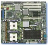
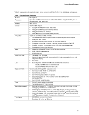
...Board Features Feature Processors Description Up to two Intel® Xeon™ processors with an FC-mPGA4 using Socket 604, and an 800-MHz Front Side Bus (FSB) Memory Chipset See Table 1 Intel® E7520 chipset: ƒ Supports 800 MHz Front Side Bus (FSB) ƒ Intel® E7520 ... 13 inches 17 Table 2. Server Board Features Table 2 summarizes the major features of critical sensor information. ƒ Intel® Light-Guided Diagnostics on critical FRU devices, such as processors, memory, and power (not on product codes SE7520BD2V and SE7520BD2VD2) ƒ Slot 6: PCI-X* 64-bit/133-...
...Board Features Feature Processors Description Up to two Intel® Xeon™ processors with an FC-mPGA4 using Socket 604, and an 800-MHz Front Side Bus (FSB) Memory Chipset See Table 1 Intel® E7520 chipset: ƒ Supports 800 MHz Front Side Bus (FSB) ƒ Intel® E7520 ... 13 inches 17 Table 2. Server Board Features Table 2 summarizes the major features of critical sensor information. ƒ Intel® Light-Guided Diagnostics on critical FRU devices, such as processors, memory, and power (not on product codes SE7520BD2V and SE7520BD2VD2) ƒ Slot 6: PCI-X* 64-bit/133-...
User Guide
Page 24
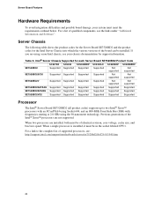
... SE7520BD2SCSID2 Supported Supported Supported Supported Supported Supported SE7520BD2VD2 Supported Supported Supported Supported Supported Supported Processor The Intel® Server Board SE7520BD2 (all product codes) supports up to the complete list of qualified components, see : http://support.intel.com/support/motherboards/server/se7520bd2/sb/CS-013540.htm 24 If you are using the 90-nanometer technology.
... SE7520BD2SCSID2 Supported Supported Supported Supported Supported Supported SE7520BD2VD2 Supported Supported Supported Supported Supported Supported Processor The Intel® Server Board SE7520BD2 (all product codes) supports up to the complete list of qualified components, see : http://support.intel.com/support/motherboards/server/se7520bd2/sb/CS-013540.htm 24 If you are using the 90-nanometer technology.
User Guide
Page 30
... server. 3. Turn off all peripheral devices connected to the server. Gently spread the retaining clips at either end of your server. See Supported Processor List for your body in contact with the key in place. 11. Align the small notch in an anti-static package. 7. Remove the... lift it in the bottom edge of the socket. Insert the bottom edge of this book. 2. Reinstall and reconnect any parts you install a processor that is inserted, carefully push straight down on the top edge of electrostatic discharge (ESD) damage to reach the DIMM sockets. 8. Position the DIMM...
... server. 3. Turn off all peripheral devices connected to the server. Gently spread the retaining clips at either end of your server. See Supported Processor List for your body in contact with the key in place. 11. Align the small notch in an anti-static package. 7. Remove the... lift it in the bottom edge of the socket. Insert the bottom edge of this book. 2. Reinstall and reconnect any parts you install a processor that is inserted, carefully push straight down on the top edge of electrostatic discharge (ESD) damage to reach the DIMM sockets. 8. Position the DIMM...

User Guide
Page 31
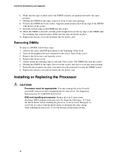
...socket handle completely. Align the pins of this book. 2. Turn off all peripheral devices connected to the server. TP00864 Figure 8. Inserting Processor 31 Turn off the server. 3. Disconnect the AC power cord from the server. 4. Opening Socket Lever 6. Observe the safety and ...ESD precautions at the beginning of the processor with the socket, and insert the processor into the socket. ✏ NOTE Make sure the alignment triangle mark and the alignment triangle cutout align correctly. TP00725 Figure...
...socket handle completely. Align the pins of this book. 2. Turn off all peripheral devices connected to the server. TP00864 Figure 8. Inserting Processor 31 Turn off the server. 3. Disconnect the AC power cord from the server. 4. Opening Socket Lever 6. Observe the safety and ...ESD precautions at the beginning of the processor with the socket, and insert the processor into the socket. ✏ NOTE Make sure the alignment triangle mark and the alignment triangle cutout align correctly. TP00725 Figure...
User Guide
Page 32
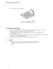
... specifc instructions for the thermal solution. 32 Gradually and equally tighten each captive screw until all screws are tight. ✏ NOTE Boxed processor thermal solutions differ depending on the heat sink corners in the captive screws on the chassis. Do not fully tighten one screw before tightening... you unpack the heat sink so you do not damage the TIM. 2. Set the heat sink over the processor, lining up the four captive screws with the four posts surrounding the processor. 3. TP00865 Figure 9. The heat sink has Thermal Interface Material (TIM) located on the bottom of it....
... specifc instructions for the thermal solution. 32 Gradually and equally tighten each captive screw until all screws are tight. ✏ NOTE Boxed processor thermal solutions differ depending on the heat sink corners in the captive screws on the chassis. Do not fully tighten one screw before tightening... you unpack the heat sink so you do not damage the TIM. 2. Set the heat sink over the processor, lining up the four captive screws with the four posts surrounding the processor. 3. TP00865 Figure 9. The heat sink has Thermal Interface Material (TIM) located on the bottom of it....
User Guide
Page 34
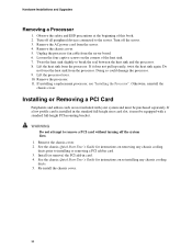
... cover. 34 Remove the AC power cord from the server board. 6. Lift the heat sink from the processor. Otherwise, reinstall the chassis cover. Hardware Installations and Upgrades Removing a Processor 1. Observe the safety and ESD precautions at the beginning of the heat sink. 7. Turn off all peripheral... the four captive screws on the corners of this book. 2. Do not force the heat sink from the processor. Doing so could damage the processor. 9. Lift the processor lever. 10. WARNING Do not attempt to installing or removing a PCI add-in card. 4. See the chassis Quick Start...
... cover. 34 Remove the AC power cord from the server board. 6. Lift the heat sink from the processor. Otherwise, reinstall the chassis cover. Hardware Installations and Upgrades Removing a Processor 1. Observe the safety and ESD precautions at the beginning of the heat sink. 7. Turn off all peripheral... the four captive screws on the corners of this book. 2. Do not force the heat sink from the processor. Doing so could damage the processor. 9. Lift the processor lever. 10. WARNING Do not attempt to installing or removing a PCI add-in card. 4. See the chassis Quick Start...
User Guide
Page 46
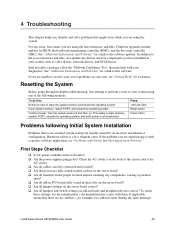
... and Software" for example, two add-in -depth troubleshooting, first attempt to all jumpers and switch settings on Problems following methods. Intel® Server Board SE7520BD2 User Guide 46 See "Additional Information and Software" for assistance. To do this: Soft boot reset to this software. 4 Troubleshooting ...are using one of the chassis and at the AC source. ‰ Are all cables correctly connected and secured? ‰ Are the processors fully seated in their sockets on the server board? ‰ Are all standoffs in boards and peripheral devices correct? To check these ...
... and Software" for example, two add-in -depth troubleshooting, first attempt to all jumpers and switch settings on Problems following methods. Intel® Server Board SE7520BD2 User Guide 46 See "Additional Information and Software" for assistance. To do this: Soft boot reset to this software. 4 Troubleshooting ...are using one of the chassis and at the AC source. ‰ Are all cables correctly connected and secured? ‰ Are the processors fully seated in their sockets on the server board? ‰ Are all standoffs in boards and peripheral devices correct? To check these ...
User Guide
Page 49
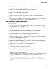
... remove the memory DIMMs and re-seat them. ‰ Make sure the processor(s) comply with the system requirements. ‰ Make sure the processor(s) have been populated according to the system requirements. ‰ Remove the processor(s) and re-seat them. ‰ Make sure the chassis standoffs are using..." function on and off to the system requirements. ‰ Carefully remove the processor(s) and re-seat them . ‰ Make sure the processor(s) comply with the system requirements. ‰ Make sure the processor(s) have failed. Verify that the video works using an add-in video controller ...
... remove the memory DIMMs and re-seat them. ‰ Make sure the processor(s) comply with the system requirements. ‰ Make sure the processor(s) have been populated according to the system requirements. ‰ Remove the processor(s) and re-seat them. ‰ Make sure the chassis standoffs are using..." function on and off to the system requirements. ‰ Carefully remove the processor(s) and re-seat them . ‰ Make sure the processor(s) comply with the system requirements. ‰ Make sure the processor(s) have failed. Verify that the video works using an add-in video controller ...
User Guide
Page 54
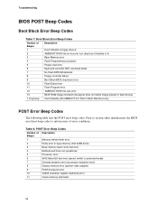
...Error Beep Codes Table 7. Table 8. Prior to system video initialization, the BIOS uses these beep codes to protected mode) 7 General exception error (processor exception error) 8 Display memory error (system video adapter) 9 ROM checksum error 10 CMOS shutdown register read error 6 Keyboard controller BAT command ...2 Parity error in base memory (first 64KB block) 3 Base memory read / write test error 4 Motherboard timer not operational 5 Processor error 6 8042 Gate A20 test error (cannot switch to inform users of diskette in root directory of error conditions.
...Error Beep Codes Table 7. Table 8. Prior to system video initialization, the BIOS uses these beep codes to protected mode) 7 General exception error (processor exception error) 8 Display memory error (system video adapter) 9 ROM checksum error 10 CMOS shutdown register read error 6 Keyboard controller BAT command ...2 Parity error in base memory (first 64KB block) 3 Base memory read / write test error 4 Motherboard timer not operational 5 Processor error 6 8042 Gate A20 test error (cannot switch to inform users of diskette in root directory of error conditions.


