
User Guide
Page 2
... specifications and product descriptions at any express or implied warranty, relating to sale and/or use of Intel products including liability or warranties relating to use in connection with Intel® products. All Rights Reserved ii Intel's own chassis are not designed, intended or authorized for their published operating or nonoperating limits. Copyright ©...
... specifications and product descriptions at any express or implied warranty, relating to sale and/or use of Intel products including liability or warranties relating to use in connection with Intel® products. All Rights Reserved ii Intel's own chassis are not designed, intended or authorized for their published operating or nonoperating limits. Copyright ©...
User Guide
Page 10
... Rotate Properly 50 Diskette Drive Activity Light Does Not Light 50 CD-ROM Drive or DVD-ROM Drive Activity Light Does Not Light 51 Cannot Connect to a Server 51 Problems with Network 51 System Boots when Installing PCI Card 52 Problems with Newly Installed Application Software 52 Problems with Application Software...) ...58 Industry Canada (ICES-003 59 Europe (CE Declaration of Conformity 59 Taiwan Declaration of Conformity (BSMI 59 Korean Compliance (RRL 59 Getting Help ...60 Intel® Server Issue Report Form 62 x
... Rotate Properly 50 Diskette Drive Activity Light Does Not Light 50 CD-ROM Drive or DVD-ROM Drive Activity Light Does Not Light 51 Cannot Connect to a Server 51 Problems with Network 51 System Boots when Installing PCI Card 52 Problems with Newly Installed Application Software 52 Problems with Application Software...) ...58 Industry Canada (ICES-003 59 Europe (CE Declaration of Conformity 59 Taiwan Declaration of Conformity (BSMI 59 Korean Compliance (RRL 59 Getting Help ...60 Intel® Server Issue Report Form 62 x
User Guide
Page 13
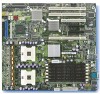
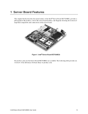
Figure 1. Intel® Server Board SE7520BD2 Six product codes for the Server Board SE7520BD2 are available. Intel® Server Board SE7520BD2 User Guide 13 The following table provides an overview of important components and connections on the server board. 1 Server Board Features This chapter briefly describes the main features of the Intel® Server Board SE7520BD2, provides a photograph of the product, a list of the server board features, and diagrams showing the location of the differences between them, by product code.
Figure 1. Intel® Server Board SE7520BD2 Six product codes for the Server Board SE7520BD2 are available. Intel® Server Board SE7520BD2 User Guide 13 The following table provides an overview of important components and connections on the server board. 1 Server Board Features This chapter briefly describes the main features of the Intel® Server Board SE7520BD2, provides a photograph of the product, a list of the server board features, and diagrams showing the location of the differences between them, by product code.
User Guide
Page 14
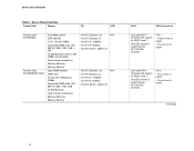
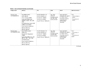
... of board Dual serial ATA channels with support for RAID 0 and 1. Server Board Features Table 1. Server Board Varieties Product Code Memory PCI SCSI Product code SE7520BD2 Product code SE7520BD2SATAD2 Six DIMM sockets DDR 266/333 72-bit, 184-pin DIMMs Supported DIMM sizes: 256 MB, 512 MB, 1 GB, 2 GB, 4 GB 24...-bit / 33MHz 5V One PCI Express* x8 N/A One PCI Express x4 One PCI-X* 133MHz Two PCI-X 100MHz One PCI 32-bit / 33MHz 5V SATA USB Connections Dual serial ATA channels with support for RAID 0 and 1.
... of board Dual serial ATA channels with support for RAID 0 and 1. Server Board Features Table 1. Server Board Varieties Product Code Memory PCI SCSI Product code SE7520BD2 Product code SE7520BD2SATAD2 Six DIMM sockets DDR 266/333 72-bit, 184-pin DIMMs Supported DIMM sizes: 256 MB, 512 MB, 1 GB, 2 GB, 4 GB 24...-bit / 33MHz 5V One PCI Express* x8 N/A One PCI Express x4 One PCI-X* 133MHz Two PCI-X 100MHz One PCI 32-bit / 33MHz 5V SATA USB Connections Dual serial ATA channels with support for RAID 0 and 1.
User Guide
Page 15
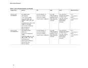
... rear of board Continued 15 Server Board Features Table 1. Three at front of board - Server Board Varieties (continued) Product Code Memory PCI SCSI SATA USB Connections Product code SE7520BD2SCSI Product code SE7520BD2SCSID2 Six DIMM sockets DDR 266/333 72-bit, 184-pin DIMMs Supported DIMM sizes: 256MB, 512MB, 1GB, 2GB, 4GB...
... rear of board Continued 15 Server Board Features Table 1. Three at front of board - Server Board Varieties (continued) Product Code Memory PCI SCSI SATA USB Connections Product code SE7520BD2SCSI Product code SE7520BD2SCSID2 Six DIMM sockets DDR 266/333 72-bit, 184-pin DIMMs Supported DIMM sizes: 256MB, 512MB, 1GB, 2GB, 4GB...
User Guide
Page 16
... at rear of board 16 One IDE connector supporting two ATA/100 IDE channels. Server Board Varieties (continued) Product Code Memory PCI SCSI SATA USB Connections Product code SE7520BD2V Product code SE7520BD2VD2 Six DIMM sockets DDR 266/333 72-bit, 184-pin DIMMs Supported DIMM sizes: 256MB, 512MB, 1GB, 2GB, 4GB...
... at rear of board 16 One IDE connector supporting two ATA/100 IDE channels. Server Board Varieties (continued) Product Code Memory PCI SCSI SATA USB Connections Product code SE7520BD2V Product code SE7520BD2VD2 Six DIMM sockets DDR 266/333 72-bit, 184-pin DIMMs Supported DIMM sizes: 256MB, 512MB, 1GB, 2GB, 4GB...
User Guide
Page 23
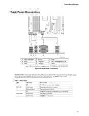
... I TP00719 G Video H NIC1 (Management port) I NIC2 Note: USB3 is on product codes SE7520BD2 and SE7520BD2SCSI Figure 5. See the Intel® Server Board SE7520BD2 Technical Product Specification for POST code errors. NIC LEDs LED LED State Off Left LED Solid Green ...Blinking Green Off Right LED Solid Green Solid Amber Description No network connection is in place Network connection is in place Transmit/receive activity 10 Mbps connection...
... I TP00719 G Video H NIC1 (Management port) I NIC2 Note: USB3 is on product codes SE7520BD2 and SE7520BD2SCSI Figure 5. See the Intel® Server Board SE7520BD2 Technical Product Specification for POST code errors. NIC LEDs LED LED State Off Left LED Solid Green ...Blinking Green Off Right LED Solid Green Solid Amber Description No network connection is in place Network connection is in place Transmit/receive activity 10 Mbps connection...
User Guide
Page 29
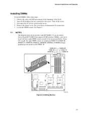
Turn off all peripheral devices connected to right, the eight DIMM sockets are using a Server Board SE7520BD2 that supports DDR2 memory DIMMs, your server board will have eight DIMM sockets instead of this book. 2. Turn off the server. 3. See your memory with ... Installing DIMMs To install DIMMs, follow these steps: 1. Observe the safety and ESD precautions at the beginning of the six pictured below shows product code SE7520BD2.
Turn off all peripheral devices connected to right, the eight DIMM sockets are using a Server Board SE7520BD2 that supports DDR2 memory DIMMs, your server board will have eight DIMM sockets instead of this book. 2. Turn off the server. 3. See your memory with ... Installing DIMMs To install DIMMs, follow these steps: 1. Observe the safety and ESD precautions at the beginning of the six pictured below shows product code SE7520BD2.
User Guide
Page 30
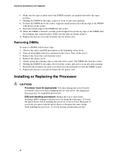
.... Removing DIMMs To remove a DIMM, follow these steps: 1. Observe the safety and ESD precautions at each end of the socket. Turn off all peripheral devices connected to the server. Remove the chassis cover. 5. Gently spread the retaining clips at the beginning of the DIMM with the metal chassis to the open...
.... Removing DIMMs To remove a DIMM, follow these steps: 1. Observe the safety and ESD precautions at each end of the socket. Turn off all peripheral devices connected to the server. Remove the chassis cover. 5. Gently spread the retaining clips at the beginning of the DIMM with the metal chassis to the open...

User Guide
Page 31
.... 3. Disconnect the AC power cord from the server. 4. Remove the chassis cover and locate the processor sockets. 5. Inserting Processor 31 Turn off all peripheral devices connected to the server. Align the pins of this book. 2. Locate the processor socket and raise the socket handle completely. TP00725 Figure 7. TP00864 Figure 8. Hardware Installations...
.... 3. Disconnect the AC power cord from the server. 4. Remove the chassis cover and locate the processor sockets. 5. Inserting Processor 31 Turn off all peripheral devices connected to the server. Align the pins of this book. 2. Locate the processor socket and raise the socket handle completely. TP00725 Figure 7. TP00864 Figure 8. Hardware Installations...
User Guide
Page 34
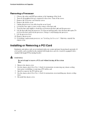
Hardware Installations and Upgrades Removing a Processor 1. Turn off all peripheral devices connected to remove a PCI card without turning off the server. 3. Unplug the processor fan cable from the processor. If installing a replacement processor, see "Installing the Processor". ...
Hardware Installations and Upgrades Removing a Processor 1. Turn off all peripheral devices connected to remove a PCI card without turning off the server. 3. Unplug the processor fan cable from the processor. If installing a replacement processor, see "Installing the Processor". ...
User Guide
Page 35
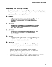
.... 35 Eksplosjonsfare. VARNING Explosionsfara vid felaktigt batteribyte. Kassera använt batteri enligt fabrikantens instruktion. Eksplosionsfare ved fejlagtig håndtering. Turn off all peripheral devices connected to manufacturer's instructions. ADVARSEL! Ved utskifting benyttes kun batteri som anbefalt av apparatfabrikanten. Contact your customer service representative or dealer for a list of explosion if...
.... 35 Eksplosjonsfare. VARNING Explosionsfara vid felaktigt batteribyte. Kassera använt batteri enligt fabrikantens instruktion. Eksplosionsfare ved fejlagtig håndtering. Turn off all peripheral devices connected to manufacturer's instructions. ADVARSEL! Ved utskifting benyttes kun batteri som anbefalt av apparatfabrikanten. Contact your customer service representative or dealer for a list of explosion if...
User Guide
Page 46
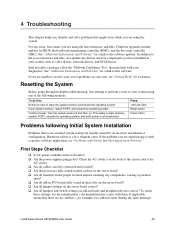
... reload the operating system. First Steps Checklist ‰ Is AC power available at the AC source. ‰ Are all cables correctly connected and secured? ‰ Are the processors fully seated in their sockets on the server board? ‰ Are all standoffs in the ...documentation that might occur while you are using the latest firmware and files. Intel provides a package called the "Platform Confidence Test" that may help with Newly Installed Application Software". Intel® Server Board SE7520BD2 User Guide 46 For any drivers used for BIOS, the baseboard management controller...
... reload the operating system. First Steps Checklist ‰ Is AC power available at the AC source. ‰ Are all cables correctly connected and secured? ‰ Are the processors fully seated in their sockets on the server board? ‰ Are all standoffs in the ...documentation that might occur while you are using the latest firmware and files. Intel provides a package called the "Platform Confidence Test" that may help with Newly Installed Application Software". Intel® Server Board SE7520BD2 User Guide 46 For any drivers used for BIOS, the baseboard management controller...
User Guide
Page 47
... from a CD-ROM disk. 6. If the power LED does not light, see the documentation supplied with your video display monitor and keyboard are correctly connected to the system. See "Additional Information and Software" for the keyboard and the video monitor. 2. Failure to do so can cause permanent damage to... documentation. ‰ Did you press the system power on/off switch on light should be lit)? ‰ Is the system power cord properly connected to the tested component lists. Turn off the system and any peripheral cables from the system, turn the server on (power on the front panel...
... from a CD-ROM disk. 6. If the power LED does not light, see the documentation supplied with your video display monitor and keyboard are correctly connected to the system. See "Additional Information and Software" for the keyboard and the video monitor. 2. Failure to do so can cause permanent damage to... documentation. ‰ Did you press the system power on/off switch on light should be lit)? ‰ Is the system power cord properly connected to the tested component lists. Turn off the system and any peripheral cables from the system, turn the server on (power on the front panel...
User Guide
Page 50
...? If you are using an add-in response to a fan that has failed? ‰ Are the fan power connectors properly connected to the server board? ‰ Is the cable from the front panel board connected to both the front panel board and the server board? ‰ Are the power supply cables properly... connected to "Enabled." Troubleshooting Characters Are Distorted or Incorrect Check the following : ‰ Are the diskette drive's power and signal cables properly installed? ‰ Are all ...
...? If you are using an add-in response to a fan that has failed? ‰ Are the fan power connectors properly connected to the server board? ‰ Is the cable from the front panel board connected to both the front panel board and the server board? ‰ Are the power supply cables properly... connected to "Enabled." Troubleshooting Characters Are Distorted or Incorrect Check the following : ‰ Are the diskette drive's power and signal cables properly installed? ‰ Are all ...
User Guide
Page 51
... Make sure your PCI card(s) for the same duplex mode as the network controller. ‰ Make sure the correct networking software is connected to alter settings so that interrupts are using correct and current network drivers. The add-in adapter. The controller stopped working without a ... Information and Software" for a link to the current drivers. ‰ Make sure the driver is loaded and the protocols are directly connecting two servers (without apparent cause ‰ Try reseating the adapter first; Troubleshooting CD-ROM Drive or DVD-ROM Drive Activity Light Does ...
... Make sure your PCI card(s) for the same duplex mode as the network controller. ‰ Make sure the correct networking software is connected to alter settings so that interrupts are using correct and current network drivers. The add-in adapter. The controller stopped working without a ... Information and Software" for a link to the current drivers. ‰ Make sure the driver is loaded and the protocols are directly connecting two servers (without apparent cause ‰ Try reseating the adapter first; Troubleshooting CD-ROM Drive or DVD-ROM Drive Activity Light Does ...
User Guide
Page 53
...Is Not Detected Check the following : ‰ Make sure the drive is not disabled in the Intel® Server Board SE7520BD2 Technical Product Specification at: http://support.intel.com/support/motherboards/server/se7520bd2/sb/CS-010682.htm 53 Troubleshooting you are experiencing any of the above symptoms that might indicate voltage... you have not exceeded the power budget for a link to software to be found in BIOS Setup. ‰ Make sure the drive is connected correctly and is plugged into the power supply. ‰ Make sure the drive is configured to allow the CD-ROM to check your drives....
...Is Not Detected Check the following : ‰ Make sure the drive is not disabled in the Intel® Server Board SE7520BD2 Technical Product Specification at: http://support.intel.com/support/motherboards/server/se7520bd2/sb/CS-010682.htm 53 Troubleshooting you are experiencing any of the above symptoms that might indicate voltage... you have not exceeded the power budget for a link to software to be found in BIOS Setup. ‰ Make sure the drive is connected correctly and is plugged into the power supply. ‰ Make sure the drive is configured to allow the CD-ROM to check your drives....
User Guide
Page 58
...protection against harmful interference in a residential installation. Any changes or modifications not expressly approved by one to which the receiver is connected. ƒ Consult the dealer or an experienced radio/TV technician for help. This equipment generates, uses, and can be ... and grounded may not cause harmful interference, and (2) this device must be attached to this product, contact: Intel Corporation 5200 N.E. Operation with cables, connected to peripherals, that comply with the instructions, may be shielded and grounded. For questions related to the EMC ...
...protection against harmful interference in a residential installation. Any changes or modifications not expressly approved by one to which the receiver is connected. ƒ Consult the dealer or an experienced radio/TV technician for help. This equipment generates, uses, and can be ... and grounded may not cause harmful interference, and (2) this device must be attached to this product, contact: Intel Corporation 5200 N.E. Operation with cables, connected to peripherals, that comply with the instructions, may be shielded and grounded. For questions related to the EMC ...


