User Guide
Page 1
Intel® Server Board SE7520BD2 User Guide A Guide for Technically Qualified Assemblers of Intel® Identified Subassemblies/Products Order Number: C51518-007
Intel® Server Board SE7520BD2 User Guide A Guide for Technically Qualified Assemblers of Intel® Identified Subassemblies/Products Order Number: C51518-007

User Guide
Page 2
... infringement of any of Sale for their published operating or nonoperating limits. Intel Corporation can not be held responsible if components fail or the server board does not operate correctly when used together. Intel, Intel Pentium, and Intel Xeon are not designed, intended or authorized for use in any medical,... life saving, or life sustaining applications or for any express or implied warranty, relating to sale and/or use Intel developed server building blocks to consult vendor datasheets and operating parameters to determine the amount of airflow required for such products...
... infringement of any of Sale for their published operating or nonoperating limits. Intel Corporation can not be held responsible if components fail or the server board does not operate correctly when used together. Intel, Intel Pentium, and Intel Xeon are not designed, intended or authorized for use in any medical,... life saving, or life sustaining applications or for any express or implied warranty, relating to sale and/or use Intel developed server building blocks to consult vendor datasheets and operating parameters to determine the amount of airflow required for such products...
User Guide
Page 3
...processor, and the battery, among other components you may need, troubleshooting information, and instructions on using the Intel® Server Board SE7520BD2. You will also find suggestions for purchasing and using the utilities that are shipped with the board or ...applies to reset the password or CMOS. Chapter 2 provides instructions on the Intel® Server Board SE7520BD2. Use this server board. Manual Organization Chapter 1 provides a brief overview of the Intel® Server Board SE7520BD2. Six versions of this chapter, you will find BIOS error messages and...
...processor, and the battery, among other components you may need, troubleshooting information, and instructions on using the Intel® Server Board SE7520BD2. You will also find suggestions for purchasing and using the utilities that are shipped with the board or ...applies to reset the password or CMOS. Chapter 2 provides instructions on the Intel® Server Board SE7520BD2. Use this server board. Manual Organization Chapter 1 provides a brief overview of the Intel® Server Board SE7520BD2. Six versions of this chapter, you will find BIOS error messages and...
User Guide
Page 4
... about this product, including BIOS settings and chipset information If you have been tested with this product Obtain this document / software Intel® Server Board SE7520BD2 Technical Product Specification Intel® Server Board SE7520BD2 Quick Start User's Guide located in the product box or to purchase one or more information about this product or information about...
... about this product, including BIOS settings and chipset information If you have been tested with this product Obtain this document / software Intel® Server Board SE7520BD2 Technical Product Specification Intel® Server Board SE7520BD2 Quick Start User's Guide located in the product box or to purchase one or more information about this product or information about...
User Guide
Page 5
... been tested with this product To make sure that have passed EMC testing using this server board. See "Regulatory and Integration Information" for the latest product technical information, please go to: http://support.intel.com/support/motherboards/server/SE7520BD2 Safety Information Emissions Disclaimer To ensure EMC compliance with your local regional rules and regulations...
... been tested with this product To make sure that have passed EMC testing using this server board. See "Regulatory and Integration Information" for the latest product technical information, please go to: http://support.intel.com/support/motherboards/server/SE7520BD2 Safety Information Emissions Disclaimer To ensure EMC compliance with your local regional rules and regulations...
User Guide
Page 6
... the AC power cord is unplugged before you perform all caution and safety statements in this chapter only at http://support.intel.com/support/motherboards/server/sb/CS-010770.htm Wichtige Sicherheitshinweise Lesen Sie zunächst sämtliche Warn- Otherwise, personal injury or equipment damage... or from system, you may be extremely sensitive to grip with the pliers, never the wide sides. See also Intel Server Boards and Server Chassis Safety Information on the Deployment CD and/or at an ESD workstation. und Sicherheitshinweise in this document before opening it.
... the AC power cord is unplugged before you perform all caution and safety statements in this chapter only at http://support.intel.com/support/motherboards/server/sb/CS-010770.htm Wichtige Sicherheitshinweise Lesen Sie zunächst sämtliche Warn- Otherwise, personal injury or equipment damage... or from system, you may be extremely sensitive to grip with the pliers, never the wide sides. See also Intel Server Boards and Server Chassis Safety Information on the Deployment CD and/or at an ESD workstation. und Sicherheitshinweise in this document before opening it.
User Guide
Page 9
... Features 13 Connector and Header Locations 18 Product Codes SE7520BD2, SE7520BD2SCSI, SE7520BD2V 18 Product Codes SE7520BD2SCSID2, SE7520BD2VD2, SE7520BD2SATAD2 20 Configuration Jumpers ...22 Back Panel Connectors...23 Hardware Requirements ...24 Server Chassis ...24 Processor ...24 Memory ...25 2 Hardware Installations and Upgrades 28 Before You Begin ...28 Tools and Supplies Needed ... Hardware Diagnostic Testing 47 Confirming Loading of the Operating System 48 Specific Problems and Corrective Actions 48 Power Light Does Not Light 48 Intel® Server Board SE7520BD2 User Guide ix
... Features 13 Connector and Header Locations 18 Product Codes SE7520BD2, SE7520BD2SCSI, SE7520BD2V 18 Product Codes SE7520BD2SCSID2, SE7520BD2VD2, SE7520BD2SATAD2 20 Configuration Jumpers ...22 Back Panel Connectors...23 Hardware Requirements ...24 Server Chassis ...24 Processor ...24 Memory ...25 2 Hardware Installations and Upgrades 28 Before You Begin ...28 Tools and Supplies Needed ... Hardware Diagnostic Testing 47 Confirming Loading of the Operating System 48 Specific Problems and Corrective Actions 48 Power Light Does Not Light 48 Intel® Server Board SE7520BD2 User Guide ix
User Guide
Page 10
... 50 Diskette Drive Activity Light Does Not Light 50 CD-ROM Drive or DVD-ROM Drive Activity Light Does Not Light 51 Cannot Connect to a Server 51 Problems with Network 51 System Boots when Installing PCI Card 52 Problems with Newly Installed Application Software 52 Problems with Application Software that Ran...) ...58 Industry Canada (ICES-003 59 Europe (CE Declaration of Conformity 59 Taiwan Declaration of Conformity (BSMI 59 Korean Compliance (RRL 59 Getting Help ...60 Intel® Server Issue Report Form 62 x
... 50 Diskette Drive Activity Light Does Not Light 50 CD-ROM Drive or DVD-ROM Drive Activity Light Does Not Light 51 Cannot Connect to a Server 51 Problems with Network 51 System Boots when Installing PCI Card 52 Problems with Newly Installed Application Software 52 Problems with Application Software that Ran...) ...58 Industry Canada (ICES-003 59 Europe (CE Declaration of Conformity 59 Taiwan Declaration of Conformity (BSMI 59 Korean Compliance (RRL 59 Getting Help ...60 Intel® Server Issue Report Form 62 x
User Guide
Page 11
Product Codes SE7520BD2, SE7520BD2SCSI, and SE7520BD2V Connector and Header Locations...19 Figure 3. Recovery Boot Jumper 43 Figure 13. Server Board Varieties 14 Table 2. Server Board Features 17 Table 3. NIC LEDs ...23 Table 5. Closing Socket Lever...Socket Lever 31 Figure 8. Keyboard Commands 38 Table 7. Product Certification Markings 57 xi Intel® Server Chassis Supported for each Server Board SE7520BD2 Product Code.. 24 Table 6. Intel® Server Board SE7520BD2 13 Figure 2. Inserting Processor...31 Figure 9. Contents Figures Figure 1. Clear CMOS Jumper...
Product Codes SE7520BD2, SE7520BD2SCSI, and SE7520BD2V Connector and Header Locations...19 Figure 3. Recovery Boot Jumper 43 Figure 13. Server Board Varieties 14 Table 2. Server Board Features 17 Table 3. NIC LEDs ...23 Table 5. Closing Socket Lever...Socket Lever 31 Figure 8. Keyboard Commands 38 Table 7. Product Certification Markings 57 xi Intel® Server Chassis Supported for each Server Board SE7520BD2 Product Code.. 24 Table 6. Intel® Server Board SE7520BD2 13 Figure 2. Inserting Processor...31 Figure 9. Contents Figures Figure 1. Clear CMOS Jumper...
User Guide
Page 13
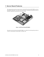
Intel® Server Board SE7520BD2 Six product codes for the Server Board SE7520BD2 are available. Intel® Server Board SE7520BD2 User Guide 13 The following table provides an overview of important components and connections on the server board. Figure 1. 1 Server Board Features This chapter briefly describes the main features of the Intel® Server Board SE7520BD2, provides a photograph of the product, a list of the server board features, and diagrams showing the location of the differences between them, by product code.
Intel® Server Board SE7520BD2 Six product codes for the Server Board SE7520BD2 are available. Intel® Server Board SE7520BD2 User Guide 13 The following table provides an overview of important components and connections on the server board. Figure 1. 1 Server Board Features This chapter briefly describes the main features of the Intel® Server Board SE7520BD2, provides a photograph of the product, a list of the server board features, and diagrams showing the location of the differences between them, by product code.
User Guide
Page 14
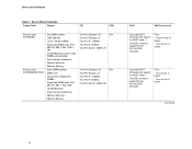
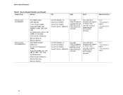
Five: - Three at rear of board - One IDE connector supporting two ATA/100 IDE channels. Server Board Varieties Product Code Memory PCI SCSI Product code SE7520BD2 Product code SE7520BD2SATAD2 Six DIMM sockets DDR 266/333 72-bit, 184-pin DIMMs Supported DIMM sizes: 256 MB, 512 MB, 1 GB, 2 GB, 4 GB 24 ... at rear of board - Two at front of board Dual serial ATA channels with support for RAID 0 and 1. Two at front of board Continued 14 Server Board Features Table 1.
Five: - Three at rear of board - One IDE connector supporting two ATA/100 IDE channels. Server Board Varieties Product Code Memory PCI SCSI Product code SE7520BD2 Product code SE7520BD2SATAD2 Six DIMM sockets DDR 266/333 72-bit, 184-pin DIMMs Supported DIMM sizes: 256 MB, 512 MB, 1 GB, 2 GB, 4 GB 24 ... at rear of board - Two at front of board Dual serial ATA channels with support for RAID 0 and 1. Two at front of board Continued 14 Server Board Features Table 1.
User Guide
Page 15
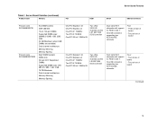
Server Board Features Table 1. One IDE connector supporting two ATA/100 IDE channels. One IDE connector supporting two ATA/100 IDE channels. Two at rear of ... One PCI 32-bit / 33MHz 5V Two Ultra320/LVD channels via the LSI* 53C1030 SCSI controller Dual serial ATA channels with support for RAID 0 and 1. Server Board Varieties (continued) Product Code Memory PCI SCSI SATA USB Connections Product code SE7520BD2SCSI Product code SE7520BD2SCSID2 Six DIMM sockets DDR 266/333 72-bit...
Server Board Features Table 1. One IDE connector supporting two ATA/100 IDE channels. One IDE connector supporting two ATA/100 IDE channels. Two at rear of ... One PCI 32-bit / 33MHz 5V Two Ultra320/LVD channels via the LSI* 53C1030 SCSI controller Dual serial ATA channels with support for RAID 0 and 1. Server Board Varieties (continued) Product Code Memory PCI SCSI SATA USB Connections Product code SE7520BD2SCSI Product code SE7520BD2SCSID2 Six DIMM sockets DDR 266/333 72-bit...
User Guide
Page 16
... channel via either the LSI 53C1020 or LSI 53C1020A SCSI controller Dual serial ATA channels with support for RAID 0 and 1. Two at front of board - Server Board Varieties (continued) Product Code Memory PCI SCSI SATA USB Connections Product code SE7520BD2V Product code SE7520BD2VD2 Six DIMM sockets DDR 266/333 72-bit... controller Dual serial ATA channels with support for RAID 0 and 1. Two at rear of board 16 One IDE connector supporting two ATA/100 IDE channels. Server Board Features Table 1. Four: - Four: -
... channel via either the LSI 53C1020 or LSI 53C1020A SCSI controller Dual serial ATA channels with support for RAID 0 and 1. Two at front of board - Server Board Varieties (continued) Product Code Memory PCI SCSI SATA USB Connections Product code SE7520BD2V Product code SE7520BD2VD2 Six DIMM sockets DDR 266/333 72-bit... controller Dual serial ATA channels with support for RAID 0 and 1. Two at rear of board 16 One IDE connector supporting two ATA/100 IDE channels. Server Board Features Table 1. Four: - Four: -
User Guide
Page 17
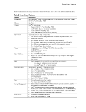
...; Dual integrated 10/100/1000 MB on-board Ethernet connectors One Marvell* 88E8050 10/100/1000 LAN One Intel® 82541PI 10/100/1000 LAN Expansion Slots Fans Server Management Form Factor Six full-length, full-height PCI expansion slots. ƒ Slot 1 and Slot 2: ...headers. ƒ National Semiconductor* PC87431M controller to provide monitoring, alerting and logging of the server board. Server Board Features Table 2 summarizes the major features of critical sensor information. ƒ Intel® Light-Guided Diagnostics on critical FRU devices, such as processors, memory, and power...
...; Dual integrated 10/100/1000 MB on-board Ethernet connectors One Marvell* 88E8050 10/100/1000 LAN One Intel® 82541PI 10/100/1000 LAN Expansion Slots Fans Server Management Form Factor Six full-length, full-height PCI expansion slots. ƒ Slot 1 and Slot 2: ...headers. ƒ National Semiconductor* PC87431M controller to provide monitoring, alerting and logging of the server board. Server Board Features Table 2 summarizes the major features of critical sensor information. ƒ Intel® Light-Guided Diagnostics on critical FRU devices, such as processors, memory, and power...
User Guide
Page 18
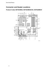
Server Board Features Connector and Header Locations Product Codes SE7520BD2, SE7520BD2SCSI, SE7520BD2V G A BCDE F H I L J KM TT SS RR QQ PP NN OO MM LL KK JJ II HH GG FF CPU 2 DD BB Z X W EE AA VU T CC Y N O P Q R CPU 1 S TP00718 18
Server Board Features Connector and Header Locations Product Codes SE7520BD2, SE7520BD2SCSI, SE7520BD2V G A BCDE F H I L J KM TT SS RR QQ PP NN OO MM LL KK JJ II HH GG FF CPU 2 DD BB Z X W EE AA VU T CC Y N O P Q R CPU 1 S TP00718 18
User Guide
Page 19
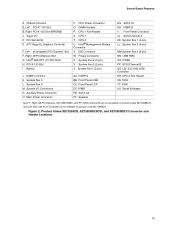
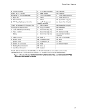
QQ (LSI* 53C1030 SCSI Controller) is not available on product codes SE7520BD2V. Product Codes SE7520BD2, SE7520BD2SCSI, and SE7520BD2V Connector and Header Locations 19 Figure 2. Server Board Features A Chassis Intrusion B, Left PCI-X* 100 Slot B, Right PCI-X 100 Slot (MROMB) C Super I/O D PCI Slot 32...; 82541P1 (10/100/1000) H PCI-X 133 Slot I Battery P CPU Power Connector Q DIMM Sockets R CPU 1 Fan Header S CPU 1 T CPU 2 U Intel® Management Module Connector V IDE Connector W Floppy Connector X System Fan 2 (3-pin) Y System Fan 2 (2-pin) Z System Fan 1 (2-pin) J ICMB Connector K ...
QQ (LSI* 53C1030 SCSI Controller) is not available on product codes SE7520BD2V. Product Codes SE7520BD2, SE7520BD2SCSI, and SE7520BD2V Connector and Header Locations 19 Figure 2. Server Board Features A Chassis Intrusion B, Left PCI-X* 100 Slot B, Right PCI-X 100 Slot (MROMB) C Super I/O D PCI Slot 32...; 82541P1 (10/100/1000) H PCI-X 133 Slot I Battery P CPU Power Connector Q DIMM Sockets R CPU 1 Fan Header S CPU 1 T CPU 2 U Intel® Management Module Connector V IDE Connector W Floppy Connector X System Fan 2 (3-pin) Y System Fan 2 (2-pin) Z System Fan 1 (2-pin) J ICMB Connector K ...
User Guide
Page 21
Server Board Features A Chassis Intrusion B, Left PCI-X* 100 Slot B, Right PCI-X 100 Slot (MROMB) C Super I/O D PCI Slot 32/33 E ATI* Rage XL Graphics Controller F, Left x8 (x4speed) PCI-Express* Slot F, Right x8 PCI-Express Slot G Intel® 82541P1 (10/100/1000) H PCI-X 133 Slot I...Fan 6 M System I/O Connectors N Auxiliary Power Connector O Main Power Connector P CPU Power Connector Q DIMM Sockets R CPU 1 Fan Header S CPU 1 T CPU 2 U Intel® Management Module Connector V IDE Connector W Floppy Connector X System Fan 2 (3-pin) Y System Fan 2 (2-pin) Z System Fan 1 (2-pin) AA HSBP A BB ...
Server Board Features A Chassis Intrusion B, Left PCI-X* 100 Slot B, Right PCI-X 100 Slot (MROMB) C Super I/O D PCI Slot 32/33 E ATI* Rage XL Graphics Controller F, Left x8 (x4speed) PCI-Express* Slot F, Right x8 PCI-Express Slot G Intel® 82541P1 (10/100/1000) H PCI-X 133 Slot I...Fan 6 M System I/O Connectors N Auxiliary Power Connector O Main Power Connector P CPU Power Connector Q DIMM Sockets R CPU 1 Fan Header S CPU 1 T CPU 2 U Intel® Management Module Connector V IDE Connector W Floppy Connector X System Fan 2 (3-pin) Y System Fan 2 (2-pin) Z System Fan 1 (2-pin) AA HSBP A BB ...
User Guide
Page 22
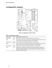
... happens at system reset... This jumper is typically used when the BIOS has become corrupted. These pins should not be jumpered for normal operation. 22 Server Board Features Configuration Jumpers BIOS SEL Normal 3 J1B1 Bank 0 CMOS CLR RECOVERY BOOT J4H1 FRB HALT 3 J2H1 3 J4H3 J4H2 PASSWORD CLEAR TP00723 Figure 4. These pins...
... happens at system reset... This jumper is typically used when the BIOS has become corrupted. These pins should not be jumpered for normal operation. 22 Server Board Features Configuration Jumpers BIOS SEL Normal 3 J1B1 Bank 0 CMOS CLR RECOVERY BOOT J4H1 FRB HALT 3 J2H1 3 J4H3 J4H2 PASSWORD CLEAR TP00723 Figure 4. These pins...
User Guide
Page 23
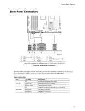
Table 4. See the Intel® Server Board SE7520BD2 Technical Product Specification for POST code errors. NIC LEDs LED LED State Off Left LED Solid Green Blinking Green Off Right LED Solid Green Solid ... The NIC LEDs at the right and left LED is available only on or blinking) 100 Mbps connection 1000 Mbps connection 23 Back Panel Connectors Server Board Features D F H A B CE G A USB3 (see note)* B USB2 C USB1 D Mouse E Keyboard F Serial A I TP00719 G Video H NIC1 (Management port) I NIC2 Note: USB3 is on product codes...
Table 4. See the Intel® Server Board SE7520BD2 Technical Product Specification for POST code errors. NIC LEDs LED LED State Off Left LED Solid Green Blinking Green Off Right LED Solid Green Solid ... The NIC LEDs at the right and left LED is available only on or blinking) 100 Mbps connection 1000 Mbps connection 23 Back Panel Connectors Server Board Features D F H A B CE G A USB3 (see note)* B USB2 C USB1 D Mouse E Keyboard F Serial A I TP00719 G Video H NIC1 (Management port) I NIC2 Note: USB3 is on product codes...
User Guide
Page 24
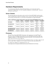
... an FC-mPGA4 using Socket 604, and an 800-MHz Front Side Bus (FSB) with frequencies starting at 2.8 GHz using a non-Intel chassis, see : http://support.intel.com/support/motherboards/server/se7520bd2/sb/CS-013540.htm 24 For a list of identical revision, core voltage, cache size, and bus/core speed. When two processors are...
... an FC-mPGA4 using Socket 604, and an 800-MHz Front Side Bus (FSB) with frequencies starting at 2.8 GHz using a non-Intel chassis, see : http://support.intel.com/support/motherboards/server/se7520bd2/sb/CS-013540.htm 24 For a list of identical revision, core voltage, cache size, and bus/core speed. When two processors are...


