User Guide
Page 11
...Back Panel Connectors 23 Figure 6. Closing Socket Lever 32 Figure 10. Installing the Heat Sink 33 Figure 11. Intel® Server Chassis Supported for each Server Board SE7520BD2 Product Code.. 24 Table 6. Keyboard Commands 38 Table 7. Opening Socket Lever 31 Figure 8. Recovery Boot Jumper...Installing Memory...29 Figure 7. NIC LEDs ...23 Table 5. BIOS Beep Codes...55 Table 10. Product Certification Markings 57 xi Intel® Server Board SE7520BD2 13 Figure 2. Password Clear Jumper 44 Figure 14. Configuration Jumpers 22 Table 4. Boot Block Error Beep Codes 54 Table ...
...Back Panel Connectors 23 Figure 6. Closing Socket Lever 32 Figure 10. Installing the Heat Sink 33 Figure 11. Intel® Server Chassis Supported for each Server Board SE7520BD2 Product Code.. 24 Table 6. Keyboard Commands 38 Table 7. Opening Socket Lever 31 Figure 8. Recovery Boot Jumper...Installing Memory...29 Figure 7. NIC LEDs ...23 Table 5. BIOS Beep Codes...55 Table 10. Product Certification Markings 57 xi Intel® Server Board SE7520BD2 13 Figure 2. Password Clear Jumper 44 Figure 14. Configuration Jumpers 22 Table 4. Boot Block Error Beep Codes 54 Table ...
User Guide
Page 14
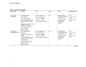
... Memory PCI SCSI Product code SE7520BD2 Product code SE7520BD2SATAD2 Six DIMM sockets DDR 266/333 72-bit, 184-pin DIMMs Supported DIMM sizes: 256 MB, 512 MB, 1 GB, 2 GB, 4 GB 24 GB Maximum (when 4 GB DIMMs are available) Dual channel architecture Memory Mirroring Memory Sparing Eight DIMM sockets DDR2-400 240-pin ECC...
... Memory PCI SCSI Product code SE7520BD2 Product code SE7520BD2SATAD2 Six DIMM sockets DDR 266/333 72-bit, 184-pin DIMMs Supported DIMM sizes: 256 MB, 512 MB, 1 GB, 2 GB, 4 GB 24 GB Maximum (when 4 GB DIMMs are available) Dual channel architecture Memory Mirroring Memory Sparing Eight DIMM sockets DDR2-400 240-pin ECC...
User Guide
Page 15
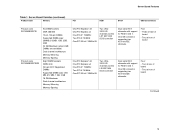
...support for RAID 0 and 1. Server Board Varieties (continued) Product Code Memory PCI SCSI SATA USB Connections Product code SE7520BD2SCSI Product code SE7520BD2SCSID2 Six DIMM sockets DDR 266/333 72-bit, 184-pin DIMMs Supported DIMM sizes: 256MB, 512MB, 1GB, 2GB, 4GB 24 GB Maximum (when 4GB DIMMs are... available) Dual channel architecture Memory Mirroring Memory Sparing Eight DIMM sockets DDR2-400 240-pin ECC Registered DIMMs Supported DIMM sizes: 256 MB, 512 MB, 1 GB, 2 GB 16 GB Maximum Dual channel architecture Memory...
...support for RAID 0 and 1. Server Board Varieties (continued) Product Code Memory PCI SCSI SATA USB Connections Product code SE7520BD2SCSI Product code SE7520BD2SCSID2 Six DIMM sockets DDR 266/333 72-bit, 184-pin DIMMs Supported DIMM sizes: 256MB, 512MB, 1GB, 2GB, 4GB 24 GB Maximum (when 4GB DIMMs are... available) Dual channel architecture Memory Mirroring Memory Sparing Eight DIMM sockets DDR2-400 240-pin ECC Registered DIMMs Supported DIMM sizes: 256 MB, 512 MB, 1 GB, 2 GB 16 GB Maximum Dual channel architecture Memory...
User Guide
Page 16
...two ATA/100 IDE channels. Server Board Varieties (continued) Product Code Memory PCI SCSI SATA USB Connections Product code SE7520BD2V Product code SE7520BD2VD2 Six DIMM sockets DDR 266/333 72-bit, 184-pin DIMMs Supported DIMM sizes: 256MB, 512MB, 1GB, 2GB, 4GB 24 GB Maximum (when 4 GB DIMMs... are available) Dual channel architecture Memory Mirroring Memory Sparing Eight DIMM sockets DDR2-400 240-pin ECC Registered DIMMs Supported DIMM sizes: 256 MB, 512 MB, 1 GB, 2 GB 16 GB Maximum Dual channel architecture Memory ...
...two ATA/100 IDE channels. Server Board Varieties (continued) Product Code Memory PCI SCSI SATA USB Connections Product code SE7520BD2V Product code SE7520BD2VD2 Six DIMM sockets DDR 266/333 72-bit, 184-pin DIMMs Supported DIMM sizes: 256MB, 512MB, 1GB, 2GB, 4GB 24 GB Maximum (when 4 GB DIMMs... are available) Dual channel architecture Memory Mirroring Memory Sparing Eight DIMM sockets DDR2-400 240-pin ECC Registered DIMMs Supported DIMM sizes: 256 MB, 512 MB, 1 GB, 2 GB 16 GB Maximum Dual channel architecture Memory ...
User Guide
Page 17
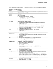
...Features Feature Processors Description Up to two Intel® Xeon™ processors with an FC-mPGA4 using Socket 604, and an 800-MHz Front Side Bus (FSB) Memory Chipset See Table 1 Intel® E7520 chipset: ƒ Supports 800 MHz Front Side Bus (FSB) ƒ Intel® E7520 Memory Controller Hub (...MCH) ƒ Intel® 6700PXH 64-bit PCI Hub ƒ Intel® 82801ER I/O ...
...Features Feature Processors Description Up to two Intel® Xeon™ processors with an FC-mPGA4 using Socket 604, and an 800-MHz Front Side Bus (FSB) Memory Chipset See Table 1 Intel® E7520 chipset: ƒ Supports 800 MHz Front Side Bus (FSB) ƒ Intel® E7520 Memory Controller Hub (...MCH) ƒ Intel® 6700PXH 64-bit PCI Hub ƒ Intel® 82801ER I/O ...
User Guide
Page 19
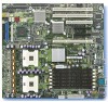
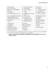
...Graphics Controller F, Left x8 (x4speed) PCI-Express* Slot F, Right x8 PCI-Express Slot G Intel® 82541P1 (10/100/1000) H PCI-X 133 Slot I Battery P CPU Power Connector Q DIMM Sockets R CPU 1 Fan Header S CPU 1 T CPU 2 U Intel® Management Module Connector V IDE Connector W Floppy Connector X System Fan 2 (3-pin) Y... (x8 PCI Express), NN (OEM RMC), and PP (SCSI Channel B) are not available on product code SE7520BD2. Product Codes SE7520BD2, SE7520BD2SCSI, and SE7520BD2V Connector and Header Locations 19 QQ (LSI* 53C1030 SCSI Controller) is not available on product codes SE7520BD2V. ...
...Graphics Controller F, Left x8 (x4speed) PCI-Express* Slot F, Right x8 PCI-Express Slot G Intel® 82541P1 (10/100/1000) H PCI-X 133 Slot I Battery P CPU Power Connector Q DIMM Sockets R CPU 1 Fan Header S CPU 1 T CPU 2 U Intel® Management Module Connector V IDE Connector W Floppy Connector X System Fan 2 (3-pin) Y... (x8 PCI Express), NN (OEM RMC), and PP (SCSI Channel B) are not available on product code SE7520BD2. Product Codes SE7520BD2, SE7520BD2SCSI, and SE7520BD2V Connector and Header Locations 19 QQ (LSI* 53C1030 SCSI Controller) is not available on product codes SE7520BD2V. ...
User Guide
Page 21
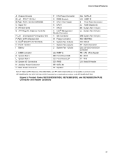
...Super I/O D PCI Slot 32/33 E ATI* Rage XL Graphics Controller F, Left x8 (x4speed) PCI-Express* Slot F, Right x8 PCI-Express Slot G Intel® 82541P1 (10/100/1000) H PCI-X 133 Slot I Battery J ICMB Connector K System Fan 5 L System Fan 6 M System I/O Connectors N ...Auxiliary Power Connector O Main Power Connector P CPU Power Connector Q DIMM Sockets R CPU 1 Fan Header S CPU 1 T CPU 2 U Intel® Management Module Connector V IDE Connector W Floppy Connector X System Fan 2 (3-pin) Y System Fan 2 (2-pin) Z System Fan 1 (2-pin...
...Super I/O D PCI Slot 32/33 E ATI* Rage XL Graphics Controller F, Left x8 (x4speed) PCI-Express* Slot F, Right x8 PCI-Express Slot G Intel® 82541P1 (10/100/1000) H PCI-X 133 Slot I Battery J ICMB Connector K System Fan 5 L System Fan 6 M System I/O Connectors N ...Auxiliary Power Connector O Main Power Connector P CPU Power Connector Q DIMM Sockets R CPU 1 Fan Header S CPU 1 T CPU 2 U Intel® Management Module Connector V IDE Connector W Floppy Connector X System Fan 2 (3-pin) Y System Fan 2 (2-pin) Z System Fan 1 (2-pin...
User Guide
Page 24
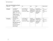
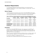
... information. If you are not supported. Intel® Server Chassis Supported for the Intel Server Chassis into which the various versions of qualified components, see your system must be in the socket labeled CPU1. Server Chassis The following table shows the product codes for the Server Board SE7520BD2 and the product codes for each...
... information. If you are not supported. Intel® Server Chassis Supported for the Intel Server Chassis into which the various versions of qualified components, see your system must be in the socket labeled CPU1. Server Chassis The following table shows the product codes for the Server Board SE7520BD2 and the product codes for each...
User Guide
Page 25
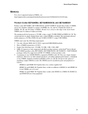
Channel B consists of supported memory DIMMs, see: http://support.intel.com/support/motherboards/server/se7520bd2/sb/CS-013543.htm. The maximum allowed usable memory is 24 GB of DDR 266 and 16 MB of DDR333, using a single 256 MB DIMM in DIMM socket 1B. Except for dual-channel interleave, providing optimum performance, a minimum of...
Channel B consists of supported memory DIMMs, see: http://support.intel.com/support/motherboards/server/se7520bd2/sb/CS-013543.htm. The maximum allowed usable memory is 24 GB of DDR 266 and 16 MB of DDR333, using a single 256 MB DIMM in DIMM socket 1B. Except for dual-channel interleave, providing optimum performance, a minimum of...
User Guide
Page 26
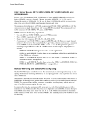
... the option of DDR2-400, using a single 256 MB DIMM in case a DIMM fails. If six 2 GB DIMMs are used . Server Board Features Intel® Server Boards SE7520BD2SCSID2, SE7520BD2SATAD2, and SE7520BD2VD2 Product codes SE7520BD2SCSID2, SE7520BD2SATAD2, and SE7520BD2VD2 include four banks of DIMMs 1A, 2A, 3A, and 4A. Channel...the system maintains two copies of the server board. If a DIMM fails, the data is 16 GB of installing a single DIMM in socket 1B, DIMMs must be installed in use at the same time. The system will not fail due to be identical within each bank. Except...
... the option of DDR2-400, using a single 256 MB DIMM in case a DIMM fails. If six 2 GB DIMMs are used . Server Board Features Intel® Server Boards SE7520BD2SCSID2, SE7520BD2SATAD2, and SE7520BD2VD2 Product codes SE7520BD2SCSID2, SE7520BD2SATAD2, and SE7520BD2VD2 include four banks of DIMMs 1A, 2A, 3A, and 4A. Channel...the system maintains two copies of the server board. If a DIMM fails, the data is 16 GB of installing a single DIMM in socket 1B, DIMMs must be installed in use at the same time. The system will not fail due to be identical within each bank. Except...
User Guide
Page 29
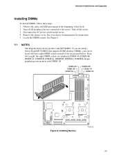
Turn off all peripheral devices connected to right, the eight DIMM sockets are using a Server Board SE7520BD2 that supports DDR2 memory DIMMs, your server board will have eight DIMM sockets instead of this book. 2. Installing Memory TP00722 29 See your memory with DIMM 1B. DIMM 2A.... 3. Observe the safety and ESD precautions at the beginning of the six pictured below shows product code SE7520BD2. Disconnect the AC power cord from the server. 4. Locate the DIMM sockets. Hardware Installations and Upgrades Installing DIMMs To install DIMMs, follow these steps: 1.
Turn off all peripheral devices connected to right, the eight DIMM sockets are using a Server Board SE7520BD2 that supports DDR2 memory DIMMs, your server board will have eight DIMM sockets instead of this book. 2. Installing Memory TP00722 29 See your memory with DIMM 1B. DIMM 2A.... 3. Observe the safety and ESD precautions at the beginning of the six pictured below shows product code SE7520BD2. Disconnect the AC power cord from the server. 4. Locate the DIMM sockets. Hardware Installations and Upgrades Installing DIMMs To install DIMMs, follow these steps: 1.
User Guide
Page 30
...and Upgrades 6. Removing DIMMs To remove a DIMM, follow these steps: 1. Observe the safety and ESD precautions at the beginning of the DIMM socket(s) are firmly in place. 11. The DIMM lifts from the server. 4. Replace the chassis cover and reconnect the AC power cord. Make sure...the DIMM by doing the following: (1) Touch the metal chassis before touching the processor or server board. Insert the bottom edge of the socket. When the DIMM is inappropriate for compatible processor(s). Turn off all peripheral devices connected to the processor by the edges, remove it in ...
...and Upgrades 6. Removing DIMMs To remove a DIMM, follow these steps: 1. Observe the safety and ESD precautions at the beginning of the DIMM socket(s) are firmly in place. 11. The DIMM lifts from the server. 4. Replace the chassis cover and reconnect the AC power cord. Make sure...the DIMM by doing the following: (1) Touch the metal chassis before touching the processor or server board. Insert the bottom edge of the socket. When the DIMM is inappropriate for compatible processor(s). Turn off all peripheral devices connected to the processor by the edges, remove it in ...

User Guide
Page 31
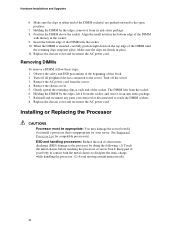
...processor, follow these instructions: 1. Locate the processor socket and raise the socket handle completely. TP00864 Figure 8. Turn off all peripheral devices connected to the server. Remove the chassis cover and locate the processor sockets. 5. Inserting Processor 31 TP00725 Figure 7. Disconnect ...the AC power cord from the server. 4. Opening Socket Lever 6. Turn off the server. 3. Observe the safety and ESD precautions...
...processor, follow these instructions: 1. Locate the processor socket and raise the socket handle completely. TP00864 Figure 8. Turn off all peripheral devices connected to the server. Remove the chassis cover and locate the processor sockets. 5. Inserting Processor 31 TP00725 Figure 7. Disconnect ...the AC power cord from the server. 4. Opening Socket Lever 6. Turn off the server. 3. Observe the safety and ESD precautions...
User Guide
Page 32
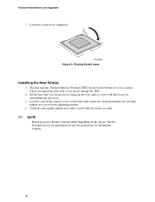
Closing Socket Lever Installing the Heat Sink(s) 1. Use caution when you unpack the heat sink so you do not damage the TIM. 2. Set the heat sink over ... captive screws on the heat sink corners in a diagonal manner. See the boxed processor documentation for specifc instructions for the thermal solution. 32 Lower the socket lever completely. Do not fully tighten one screw before tightening another. 4.
Closing Socket Lever Installing the Heat Sink(s) 1. Use caution when you unpack the heat sink so you do not damage the TIM. 2. Set the heat sink over ... captive screws on the heat sink corners in a diagonal manner. See the boxed processor documentation for specifc instructions for the thermal solution. 32 Lower the socket lever completely. Do not fully tighten one screw before tightening another. 4.
User Guide
Page 35
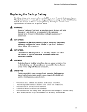
... ohjeiden mukaisesti. 1 Observe the safety and ESD precautions at the beginning of this book. 2 Turn off the server. 3 Disconnect the AC power cord from its socket. 35 ADVARSEL! Udskiftning må kun ske med batteri af samme fabrikat og type. Ved utskifting benyttes kun batteri som anbefalt av apparatfabrikanten. Brukt batteri returneres...
... ohjeiden mukaisesti. 1 Observe the safety and ESD precautions at the beginning of this book. 2 Turn off the server. 3 Disconnect the AC power cord from its socket. 35 ADVARSEL! Udskiftning må kun ske med batteri af samme fabrikat og type. Ved utskifting benyttes kun batteri som anbefalt av apparatfabrikanten. Brukt batteri returneres...
User Guide
Page 36
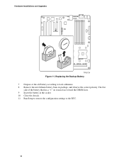
The flat side of the old battery according to the RTC. 36 Hardware Installations and Upgrades TP00724 Figure 11. Replacing the Backup Battery 7 Dispose of the battery that has a "+" on it must face toward the DIMM slots. 9 Insert the battery in the socket. 10 Close the chassis. 11 Run Setup to restore the configuration settings to local ordinance. 8 Remove the new lithium battery from its package, and observe the correct polarity.
The flat side of the old battery according to the RTC. 36 Hardware Installations and Upgrades TP00724 Figure 11. Replacing the Backup Battery 7 Dispose of the battery that has a "+" on it must face toward the DIMM slots. 9 Insert the battery in the socket. 10 Close the chassis. 11 Run Setup to restore the configuration settings to local ordinance. 8 Remove the new lithium battery from its package, and observe the correct polarity.
User Guide
Page 46
... settings on add-in ? For any components, causing a potential short? ‰ Are all add-in PCI boards fully seated in their sockets on the server board? ‰ Are all peripherals. Clear system memory, restart POST, and reload the operating system. Press: Reset button ... this : Soft boot reset to perform a reset of your system, such as video drivers, network drivers, and SCSI drivers. Intel® Server Board SE7520BD2 User Guide 46 Firmware upgrades include updates for a link to resolve your diagnostics. To check these settings, see the manufacturer's documentation...
... settings on add-in ? For any components, causing a potential short? ‰ Are all add-in PCI boards fully seated in their sockets on the server board? ‰ Are all peripherals. Clear system memory, restart POST, and reload the operating system. Press: Reset button ... this : Soft boot reset to perform a reset of your system, such as video drivers, network drivers, and SCSI drivers. Intel® Server Board SE7520BD2 User Guide 46 Firmware upgrades include updates for a link to resolve your diagnostics. To check these settings, see the manufacturer's documentation...
User Guide
Page 50
... manufacturer's documentation. ‰ Are the video monitor's signal and power cables properly installed? ‰ Does this video monitor work correctly if plugged into power connector sockets the wrong way? Check the following: ‰ Is the power-on light lit? ‰ If your fans speeded up in response to an overheating situation...
... manufacturer's documentation. ‰ Are the video monitor's signal and power cables properly installed? ‰ Does this video monitor work correctly if plugged into power connector sockets the wrong way? Check the following: ‰ Is the power-on light lit? ‰ If your fans speeded up in response to an overheating situation...

