
Manual
Page 5
...Drive (X.H.D 86 4-9 Teaming 87 Chapter 5 Appendix...89 5-1 Configuring SATA Hard Drive(s 89 5-1-1 Configuring Intel ICH10R SATA Controllers 89 5-1-2 Configuring JMicron JMB362/GIGABYTE SATA2 SATA Controller 97 5-1-3 Configuring Marvell 9128 SATA Controller 103 5-1-4 Making a SATA RAID/AHCI Driver Diskette 108 5-1-5 Installing the SATA RAID/AHCI Driver ... Configuring Microphone Recording 128 5-2-5 Using the Sound Recorder 130 5-3 Troubleshooting 131 5-3-1 Frequently Asked Questions 131 5-3-2 Troubleshooting Procedure 132 5-4 POST Error Code 134 5-5 Regulatory Statements 138 - 5 -
...Drive (X.H.D 86 4-9 Teaming 87 Chapter 5 Appendix...89 5-1 Configuring SATA Hard Drive(s 89 5-1-1 Configuring Intel ICH10R SATA Controllers 89 5-1-2 Configuring JMicron JMB362/GIGABYTE SATA2 SATA Controller 97 5-1-3 Configuring Marvell 9128 SATA Controller 103 5-1-4 Making a SATA RAID/AHCI Driver Diskette 108 5-1-5 Installing the SATA RAID/AHCI Driver ... Configuring Microphone Recording 128 5-2-5 Using the Sound Recorder 130 5-3 Troubleshooting 131 5-3-1 Frequently Asked Questions 131 5-3-2 Troubleshooting Procedure 132 5-4 POST Error Code 134 5-5 Regulatory Statements 138 - 5 -

Manual
Page 7
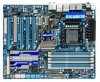
... 2) For error code information, please refer to a hardware limitation, the PCIEX1_1 slot can only accommodate a shorter PCI Express x1 expansion card. LED PHASE LED KB_MS R_SPDIF ATX_12V_2X CMOS_SW USB_1394_ESATA_2 USB_1394_ESATA_1 CPU_FAN CPU Voltage L1/2/3 CPU TEMP L1/2 LGA1366 RST_SW PW_SW GA-X58A-UD7 PWR_FAN USB_LAN ... Intel® ICH10R Marvell 9128 SATA2_1 SATA2_0 SATA2_3 SATA2_2 SATA2_5 SATA2_4 GSATA3_7 GSATA3_6 SYS_FAN3 TSB43AB23 GIGABYTE SATA2 Debug LED (Note 2) GSATA2_9 GSATA2_8 SYS_FAN2 F_USB2 IDE F_PANEL FDD F_1394 F_USB1 (Note 1) Due to Chapter 5. - 7 -
... 2) For error code information, please refer to a hardware limitation, the PCIEX1_1 slot can only accommodate a shorter PCI Express x1 expansion card. LED PHASE LED KB_MS R_SPDIF ATX_12V_2X CMOS_SW USB_1394_ESATA_2 USB_1394_ESATA_1 CPU_FAN CPU Voltage L1/2/3 CPU TEMP L1/2 LGA1366 RST_SW PW_SW GA-X58A-UD7 PWR_FAN USB_LAN ... Intel® ICH10R Marvell 9128 SATA2_1 SATA2_0 SATA2_3 SATA2_2 SATA2_5 SATA2_4 GSATA3_7 GSATA3_6 SYS_FAN3 TSB43AB23 GIGABYTE SATA2 Debug LED (Note 2) GSATA2_9 GSATA2_8 SYS_FAN2 F_USB2 IDE F_PANEL FDD F_1394 F_USB1 (Note 1) Due to Chapter 5. - 7 -

Manual
Page 131
... The following Award BIOS beep code descriptions may help you identify possible computer problems. (For reference only.) 1 short: System boots successfully 1 long, 3 short: Keyboard error 2 short: CMOS setting error 1 long, 9 short: BIOS ROM error 1 long, 1 short: Memory or motherboard error Continuous long beeps: Graphics card ...driver." Appendix Then install the onboard HD audio driver from the motherboard driver disk or download the audio driver from GIGABYTE's website to show the advanced options. Press to the maximum volume? If your board doesn't have a clearing CMOS...
... The following Award BIOS beep code descriptions may help you identify possible computer problems. (For reference only.) 1 short: System boots successfully 1 long, 3 short: Keyboard error 2 short: CMOS setting error 1 long, 9 short: BIOS ROM error 1 long, 1 short: Memory or motherboard error Continuous long beeps: Graphics card ...driver." Appendix Then install the onboard HD audio driver from the motherboard driver disk or download the audio driver from GIGABYTE's website to show the advanced options. Press to the maximum volume? If your board doesn't have a clearing CMOS...
Manual
Page 134
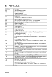
...including brand, SMI type and CPU level Initial interrupts vector table. a value of RTC value: e.g. 5-4 POST Error Code POST (hex) CFh C0h C1h C3h C5h 01h 02h 03h 05h 07h 08h 0Ah 0Eh 10h 12h 14h 16h... 18h 1Bh 1Dh 23h Description Test CMOS R/W functionality Early chipset initialization: -Disable shadow RAM - Clear CMOS error flag 1. Clear 8042 interface 2. Enable keyboard interface 1. Blank out screen 2. Also set real-time clock power status,...
...including brand, SMI type and CPU level Initial interrupts vector table. a value of RTC value: e.g. 5-4 POST Error Code POST (hex) CFh C0h C1h C3h C5h 01h 02h 03h 05h 07h 08h 0Ah 0Eh 10h 12h 14h 16h... 18h 1Bh 1Dh 23h Description Test CMOS R/W functionality Early chipset initialization: -Disable shadow RAM - Clear CMOS error flag 1. Clear 8042 interface 2. Enable keyboard interface 1. Blank out screen 2. Also set real-time clock power status,...

Manual
Page 136
... SYSID structure 1. Auto assign ports to onboard COM ports if the corresponding item in stack back to continue: 2. If errors occur, report errors & wait for full screen logo) 3. Call chipset power management hook 2. Set up ACPI table at top of IRQs ...6Fh 75h 77h 7Ah 7Ch 7Fh 82h 83h 84h 85h 87h 89h 8Bh 8Dh 8Fh 93h Description Initialize the combined Trend Anti-Virus code 1. Initialize floppy controller 2. APM initialization Clear noise of the memory 1. If password is supported - Invoke all PCI ROMs (except...
... SYSID structure 1. Auto assign ports to onboard COM ports if the corresponding item in stack back to continue: 2. If errors occur, report errors & wait for full screen logo) 3. Call chipset power management hook 2. Set up ACPI table at top of IRQs ...6Fh 75h 77h 7Ah 7Ch 7Fh 82h 83h 84h 85h 87h 89h 8Bh 8Dh 8Fh 93h Description Initialize the combined Trend Anti-Virus code 1. Initialize floppy controller 2. APM initialization Clear noise of the memory 1. If password is supported - Invoke all PCI ROMs (except...


