
Manual
Page 1
...GIGABYTE eXtreme Hard Drive (X.H.D) Instructions:(Note 2) Before launching X.H.D, make sure the new drive is added. All with which you can build a RAID 0, RAID 1, or other supported RAID array depending on your needs and hardware components. 3. Setting Up a RAID-Ready System Step 1: Configure the system BIOS Enter the system BIOS... steps to set up a RAID-ready system and configure it for the Intel SATA controllers. eXtreme Hard Drive (X.H.D) With GIGABYTE eXtreme Hard Drive (X.H.D)(Note 1), users can click the Xpress Install All button to automatically install all of data. (Note ...
...GIGABYTE eXtreme Hard Drive (X.H.D) Instructions:(Note 2) Before launching X.H.D, make sure the new drive is added. All with which you can build a RAID 0, RAID 1, or other supported RAID array depending on your needs and hardware components. 3. Setting Up a RAID-Ready System Step 1: Configure the system BIOS Enter the system BIOS... steps to set up a RAID-ready system and configure it for the Intel SATA controllers. eXtreme Hard Drive (X.H.D) With GIGABYTE eXtreme Hard Drive (X.H.D)(Note 1), users can click the Xpress Install All button to automatically install all of data. (Note ...

Manual
Page 3
...copied, translated, transmitted, or published in the use GIGABYTE's unique features, read or download the information on/from the Support&Downloads\Motherboard\Technology Guide page on your motherboard revision before updating motherboard BIOS, drivers, or when looking for technical information. For... product-related information, check on our website at: http://www.gigabyte.com.tw Identifying Your Motherboard Revision The revision number on ...
...copied, translated, transmitted, or published in the use GIGABYTE's unique features, read or download the information on/from the Support&Downloads\Motherboard\Technology Guide page on your motherboard revision before updating motherboard BIOS, drivers, or when looking for technical information. For... product-related information, check on our website at: http://www.gigabyte.com.tw Identifying Your Motherboard Revision The revision number on ...

Manual
Page 4
Table of Contents Box Contents...6 Optional Items...6 GA-X58A-UD7 Motherboard Layout 7 Block Diagram...8 Chapter 1 Hardware Installation 9 1-1 Installation Precautions 9 1-2 Product Specifications 10 1-3 Installing the CPU and CPU Cooler 13 1-3-1 ... Panel Connectors 22 1-10 Onboard LEDs and Switches 24 1-11 Internal Connectors 27 Chapter 2 BIOS Setup 37 2-1 Startup Screen 38 2-2 The Main Menu 39 2-3 MB Intelligent Tweaker(M.I.T 41 2-4 Standard CMOS Features 51 2-5 Advanced BIOS Features 53 2-6 Integrated Peripherals 55 2-7 Power Management Setup 59 2-8 PC Health Status 61...
Table of Contents Box Contents...6 Optional Items...6 GA-X58A-UD7 Motherboard Layout 7 Block Diagram...8 Chapter 1 Hardware Installation 9 1-1 Installation Precautions 9 1-2 Product Specifications 10 1-3 Installing the CPU and CPU Cooler 13 1-3-1 ... Panel Connectors 22 1-10 Onboard LEDs and Switches 24 1-11 Internal Connectors 27 Chapter 2 BIOS Setup 37 2-1 Startup Screen 38 2-2 The Main Menu 39 2-3 MB Intelligent Tweaker(M.I.T 41 2-4 Standard CMOS Features 51 2-5 Advanced BIOS Features 53 2-6 Integrated Peripherals 55 2-7 Power Management Setup 59 2-8 PC Health Status 61...

Manual
Page 5
...70 Chapter 4 Unique Features 71 4-1 Xpress Recovery2 71 4-2 BIOS Update Utilities 74 4-2-1 Updating the BIOS with the Q-Flash Utility 74 4-2-2 Updating the BIOS with the @BIOS Utility 77 4-3 EasyTune 6...78 4-4 Dynamic Energy Saver™... 2 79 4-5 Q-Share...81 4-6 Smart 6™ ...82 4-7 Auto Green...85 4-8 eXtreme Hard Drive (X.H.D 86 4-9 Teaming 87 Chapter 5 Appendix...89 5-1 Configuring SATA Hard Drive(s 89 5-1-1 Configuring Intel ICH10R SATA Controllers 89 5-1-2 Configuring JMicron JMB362/GIGABYTE...
...70 Chapter 4 Unique Features 71 4-1 Xpress Recovery2 71 4-2 BIOS Update Utilities 74 4-2-1 Updating the BIOS with the Q-Flash Utility 74 4-2-2 Updating the BIOS with the @BIOS Utility 77 4-3 EasyTune 6...78 4-4 Dynamic Energy Saver™... 2 79 4-5 Q-Share...81 4-6 Smart 6™ ...82 4-7 Auto Green...85 4-8 eXtreme Hard Drive (X.H.D 86 4-9 Teaming 87 Chapter 5 Appendix...89 5-1 Configuring SATA Hard Drive(s 89 5-1-1 Configuring Intel ICH10R SATA Controllers 89 5-1-2 Configuring JMicron JMB362/GIGABYTE...

Manual
Page 8
... (100 MHz) JMicron JMB362 Intel® ICH10R 2 PCI Express x1 x1 2 eSATA 3Gb/s 2 SATA 3Gb/s ATA-133/100/66/33 IDE Channel GIGABYTE SATA2 PCI Bus TSB43AB23 CODEC Dual BIOS 6 SATA 3Gb/s 10 USB 2.0/1.1 LPC Bus IT8720 Floppy PS/2 KB/Mouse 3 IEEE 1394a Surround Speaker Out Center/Subwoofer Speaker Out Side Speaker...
... (100 MHz) JMicron JMB362 Intel® ICH10R 2 PCI Express x1 x1 2 eSATA 3Gb/s 2 SATA 3Gb/s ATA-133/100/66/33 IDE Channel GIGABYTE SATA2 PCI Bus TSB43AB23 CODEC Dual BIOS 6 SATA 3Gb/s 10 USB 2.0/1.1 LPC Bus IT8720 Floppy PS/2 KB/Mouse 3 IEEE 1394a Surround Speaker Out Center/Subwoofer Speaker Out Side Speaker...

Manual
Page 12
..., the PCIEX16_1 slot will depend on the CPU/ system cooler you install them in EasyTune may differ by motherboard model. Hardware Installation - 12 - Hardware Monitor w w w w w w BIOS w w w w Unique Features w w w w w w w w w w w w Bundled Software w System voltage detection CPU/North Bridge temperature detection CPU/System/Power fan speed detection CPU overheating warning CPU fan fail warning...
..., the PCIEX16_1 slot will depend on the CPU/ system cooler you install them in EasyTune may differ by motherboard model. Hardware Installation - 12 - Hardware Monitor w w w w w w BIOS w w w w Unique Features w w w w w w w w w w w w Bundled Software w System voltage detection CPU/North Bridge temperature detection CPU/System/Power fan speed detection CPU overheating warning CPU fan fail warning...

Manual
Page 17
... with two or four modules, it in Flex Memory Mode will automatically detect the specifications and capacity of the memory. ory is installed, the BIOS will appear during the POST. The six DDR3 memory sockets are unable to install them in Dual/3 Channel mode/performance. - 17 - If ...is recommended that the motherboard supports the memory. When enabling 3 Channel mode with two memory modules, be sure to be used . (Go to GIGABYTE's website for the latest memory support list.) • Always turn off the computer and unplug the power cord from the power outlet before installing ...
... with two or four modules, it in Flex Memory Mode will automatically detect the specifications and capacity of the memory. ory is installed, the BIOS will appear during the POST. The six DDR3 memory sockets are unable to install them in Dual/3 Channel mode/performance. - 17 - If ...is recommended that the motherboard supports the memory. When enabling 3 Channel mode with two memory modules, be sure to be used . (Go to GIGABYTE's website for the latest memory support list.) • Always turn off the computer and unplug the power cord from the power outlet before installing ...

Manual
Page 19
...card straight up from the chassis back panel. 2. 1-6 Installing an Expansion Card Read the following guidelines before installing an expansion card to make any required BIOS changes for your card. Hardware Installation Carefully read the manual that supports your expansion card(s). 7. If necessary, go to... BIOS Setup to prevent hardware damage. Make sure the card is fully inserted into the slot. 4. Locate an expansion slot that came with the slot, and...
...card straight up from the chassis back panel. 2. 1-6 Installing an Expansion Card Read the following guidelines before installing an expansion card to make any required BIOS changes for your card. Hardware Installation Carefully read the manual that supports your expansion card(s). 7. If necessary, go to... BIOS Setup to prevent hardware damage. Make sure the card is fully inserted into the slot. 4. Locate an expansion slot that came with the slot, and...

Manual
Page 32
... cord and restart your computer. • Always turn off your SATA hard drive. 12) BAT The battery provides power to keep the values (such as BIOS configurations, date, and time information) in accordance with SATA 3Gb/s and SATA 1.5Gb/s standards. self or uncertain about the battery model. • When installing the...
... cord and restart your computer. • Always turn off your SATA hard drive. 12) BAT The battery provides power to keep the values (such as BIOS configurations, date, and time information) in accordance with SATA 3Gb/s and SATA 1.5Gb/s standards. self or uncertain about the battery model. • When installing the...

Manual
Page 33
... - 33 - RESRES+ CICI+ PWR+ PWR- The LED keeps blinking when the sys- The LED is off when the system is detected, the BIOS may configure the way to turn off (S5). • PW (Power Switch, Red): Connects to the reset switch on the chassis front panel. The... connecting the cables. This function requires a chassis with a chassis intrusion switch/sensor. When connecting your system using the power switch (refer to Chapter 2, "BIOS Setup," "Power Management Setup," for information about beep codes. • HD (Hard Drive Activity LED, Blue) Connects to the pin assignments below. You...
... - 33 - RESRES+ CICI+ PWR+ PWR- The LED keeps blinking when the sys- The LED is off when the system is detected, the BIOS may configure the way to turn off (S5). • PW (Power Switch, Red): Connects to the reset switch on the chassis front panel. The... connecting the cables. This function requires a chassis with a chassis intrusion switch/sensor. When connecting your system using the power switch (refer to Chapter 2, "BIOS Setup," "Power Management Setup," for information about beep codes. • HD (Hard Drive Activity LED, Blue) Connects to the pin assignments below. You...

Manual
Page 37
... Self-Test (POST) during the POST. To access the BIOS Setup program, press the key during the POST when the power is potentially risky, if you not flash the BIOS. To upgrade the BIOS, use either the GIGABYTE Q-Flash or @BIOS utility. • Q-Flash allows the user to quickly and... easily upgrade or back up BIOS without entering the operating system. • @BIOS is a Windows-based utility that you do not ...
... Self-Test (POST) during the POST. To access the BIOS Setup program, press the key during the POST when the power is potentially risky, if you not flash the BIOS. To upgrade the BIOS, use either the GIGABYTE Q-Flash or @BIOS utility. • Q-Flash allows the user to quickly and... easily upgrade or back up BIOS without entering the operating system. • @BIOS is a Windows-based utility that you do not ...

Manual
Page 38
... used for one time only. After system restart, the device boot order will directly boot from the device configured in Boot Menu. Motherboard Model BIOS Version X58A-UD7 D33 . . . . : BIOS Setup : XpressRecovery2 : Boot Menu : Qflash 10/27/2009-X58-ICH10-7A89QC0IC-00 Function Keys Function Keys Function Keys: : POST SCREEN Press the key to...
... used for one time only. After system restart, the device boot order will directly boot from the device configured in Boot Menu. Motherboard Model BIOS Version X58A-UD7 D33 . . . . : BIOS Setup : XpressRecovery2 : Boot Menu : Qflash 10/27/2009-X58-ICH10-7A89QC0IC-00 Function Keys Function Keys Function Keys: : POST SCREEN Press the key to...

Manual
Page 39
...Select Item F10: Save & Exit Setup Change CPU's Clock & Voltage F11: Save CMOS to BIOS F12: Load CMOS from BIOS BIOS Setup Program Function Keys Move the selection bar to select an item Execute command or enter the ...submenu Main Menu: Exit the BIOS Setup program Submenus: Exit current submenu Increase the numeric value or make changes Decrease ... the submenu. • If you do not find the settings you enter the BIOS Setup program, the Main Menu (as usual, select the Load Optimized Defaults item to set your system ...
...Select Item F10: Save & Exit Setup Change CPU's Clock & Voltage F11: Save CMOS to BIOS F12: Load CMOS from BIOS BIOS Setup Program Function Keys Move the selection bar to select an item Execute command or enter the ...submenu Main Menu: Exit the BIOS Setup program Submenus: Exit current submenu Increase the numeric value or make changes Decrease ... the submenu. • If you do not find the settings you enter the BIOS Setup program, the Main Menu (as usual, select the Load Optimized Defaults item to set your system ...

Manual
Page 40
...and date, hard drive types, floppy disk drive types, and the type of errors that stop the system boot, etc. Advanced BIOS Features Use this menu to configure the device boot order, advanced features available on the CPU, and the primary display adapter. Integrated...audio, and integrated LAN, etc. Power Management Setup Use this menu to a profile. A supervisor password allows you to save the current BIOS settings to see information about autodetected system/CPU temperature, system voltage and fan speed, etc. Load Fail-Safe Defaults Fail-Safe defaults are ...
...and date, hard drive types, floppy disk drive types, and the type of errors that stop the system boot, etc. Advanced BIOS Features Use this menu to configure the device boot order, advanced features available on the CPU, and the primary display adapter. Integrated...audio, and integrated LAN, etc. Power Management Setup Use this menu to a profile. A supervisor password allows you to save the current BIOS settings to see information about autodetected system/CPU temperature, system voltage and fan speed, etc. Load Fail-Safe Defaults Fail-Safe defaults are ...

Manual
Page 41
... Rate(CMD) - Auto x tRP - Incorrectly doing overclock/overvoltage may result in damage to CPU, chipset, or memory and reduce the useful life of these components. BIOS Setup Auto x tRP - Auto x tRCD - Auto x Command Rate(CMD) - Auto >>>>> Channel C x CAS Latency Time - Auto } Advanced DRAM Features [Press Enter] Voltage Types Normal Current Load...
... Rate(CMD) - Auto x tRP - Incorrectly doing overclock/overvoltage may result in damage to CPU, chipset, or memory and reduce the useful life of these components. BIOS Setup Auto x tRP - Auto x tRCD - Auto x Command Rate(CMD) - Auto >>>>> Channel C x CAS Latency Time - Auto } Advanced DRAM Features [Press Enter] Voltage Types Normal Current Load...

Manual
Page 42
...: Exit F1: General Help F7: Optimized Defaults CPU Clock Ratio (Note) Allows you to determine whether to alter the clock ratio for the installed CPU. BIOS Setup - 42 -
...: Exit F1: General Help F7: Optimized Defaults CPU Clock Ratio (Note) Allows you to determine whether to alter the clock ratio for the installed CPU. BIOS Setup - 42 -
Manual
Page 43
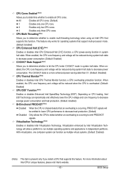
...) (Note) This item is a more information about Intel CPUs' unique features, please visit Intel's website. - 43 - Virtualization Technology (Note) Enables or disables Intel Virtualization Technology. BIOS Setup With virtualization, one CPU core. 2 Enables only two CPU cores. 3 Enables only three CPU cores. For more enhanced power-saving state than C1. (Default...
...) (Note) This item is a more information about Intel CPUs' unique features, please visit Intel's website. - 43 - Virtualization Technology (Note) Enables or disables Intel Virtualization Technology. BIOS Setup With virtualization, one CPU core. 2 Enables only two CPU cores. 3 Enables only three CPU cores. For more enhanced power-saving state than C1. (Default...

Manual
Page 44
... Move Enter: Select F5: Previous Values +/-/PU/PD: Value F10: Save F6: Fail-Safe Defaults ESC: Exit F1: General Help F7: Optimized Defaults BIOS Setup - 44 - Options are : Auto (default), x12~x48. Options are : Auto (default), x36, x44, x48, Slow Mode.
... Move Enter: Select F5: Previous Values +/-/PU/PD: Value F10: Save F6: Fail-Safe Defaults ESC: Exit F1: General Help F7: Optimized Defaults BIOS Setup - 44 - Options are : Auto (default), x12~x48. Options are : Auto (default), x36, x44, x48, Slow Mode.

Manual
Page 45
... adjustable range is from 100 MHz to manually set the CPU clock prior to adjust the amplitude of the PCI Express and North Bridge clock. BIOS Setup Auto sets the PCIe clock frequency to standard 100 MHz. (Default: Auto) >>>>> Advanced Clock Control CPU Clock Drive Allows you to the CPU clock...
... adjustable range is from 100 MHz to manually set the CPU clock prior to adjust the amplitude of the PCI Express and North Bridge clock. BIOS Setup Auto sets the PCIe clock frequency to standard 100 MHz. (Default: Auto) >>>>> Advanced Clock Control CPU Clock Drive Allows you to the CPU clock...
Manual
Page 46
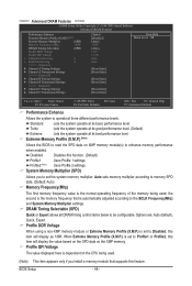
...) Profile1 Uses Profile 1 settings. Profile QPI Voltage The value displayed here is the normal operating frequency of the memory being used ; BIOS Setup - 46 - Extreme Memory Profile (X.M.P.) (Note) Allows the BIOS to read the SPD data on XMP memory module(s) to the BCLK Frequency(Mhz) and System Memory Multiplier settings. System Memory...
...) Profile1 Uses Profile 1 settings. Profile QPI Voltage The value displayed here is the normal operating frequency of the memory being used ; BIOS Setup - 46 - Extreme Memory Profile (X.M.P.) (Note) Allows the BIOS to read the SPD data on XMP memory module(s) to the BCLK Frequency(Mhz) and System Memory Multiplier settings. System Memory...


