
Manual
Page 1
... driver disk. Setting Up a RAID-Ready System Step 1: Configure the system BIOS Enter the system BIOS Setup program, set up a RAID-ready system and configure it for complex and time-consuming configurations. eXtreme Hard Drive (X.H.D) With GIGABYTE eXtreme Hard Drive (X.H.D)(Note 1), users can quickly configure a RAIDready system for the Intel SATA controllers. For a RAID 0 array that before you run the X.H.D utility, back up all motherboard drivers, including the X.H.D utility. A. Step 2: Install the RAID driver and operating system The X.H.D utility supports Windows...
... driver disk. Setting Up a RAID-Ready System Step 1: Configure the system BIOS Enter the system BIOS Setup program, set up a RAID-ready system and configure it for complex and time-consuming configurations. eXtreme Hard Drive (X.H.D) With GIGABYTE eXtreme Hard Drive (X.H.D)(Note 1), users can quickly configure a RAIDready system for the Intel SATA controllers. For a RAID 0 array that before you run the X.H.D utility, back up all motherboard drivers, including the X.H.D utility. A. Step 2: Install the RAID driver and operating system The X.H.D utility supports Windows...

Manual
Page 3
... prior notice. Check your motherboard looks like this product, GIGABYTE provides the following types of documentations: For quick set-up of GIGABYTE. Example: Changes to use of this manual may be made by copyright laws and is 1.0. For detailed product information, carefully read or download the information on/from the Support&Downloads\Motherboard\Technology Guide page on your motherboard revision before updating motherboard BIOS, drivers, or when looking for...
... prior notice. Check your motherboard looks like this product, GIGABYTE provides the following types of documentations: For quick set-up of GIGABYTE. Example: Changes to use of this manual may be made by copyright laws and is 1.0. For detailed product information, carefully read or download the information on/from the Support&Downloads\Motherboard\Technology Guide page on your motherboard revision before updating motherboard BIOS, drivers, or when looking for...

Manual
Page 4
... 1-5-2 Installing a Memory 18 1-6 Installing an Expansion Card 19 1-7 Setup of ATI CrossFireX™/SLI Configuration 20 1-8 Installing the SATA Bracket 21 1-9 Back Panel Connectors 22 1-10 Onboard LEDs and Switches 24 1-11 Internal Connectors 27 Chapter 2 BIOS Setup 37 2-1 Startup Screen 38 2-2 The Main Menu 39 2-3 MB Intelligent Tweaker(M.I.T 41 2-4 Standard CMOS Features 51 2-5 Advanced BIOS Features 53 2-6 Integrated Peripherals 55 2-7 Power Management Setup 59 2-8 PC Health Status 61 2-9 Load Fail-Safe Defaults 63 2-10 Load Optimized Defaults 63 2-11 Set...
... 1-5-2 Installing a Memory 18 1-6 Installing an Expansion Card 19 1-7 Setup of ATI CrossFireX™/SLI Configuration 20 1-8 Installing the SATA Bracket 21 1-9 Back Panel Connectors 22 1-10 Onboard LEDs and Switches 24 1-11 Internal Connectors 27 Chapter 2 BIOS Setup 37 2-1 Startup Screen 38 2-2 The Main Menu 39 2-3 MB Intelligent Tweaker(M.I.T 41 2-4 Standard CMOS Features 51 2-5 Advanced BIOS Features 53 2-6 Integrated Peripherals 55 2-7 Power Management Setup 59 2-8 PC Health Status 61 2-9 Load Fail-Safe Defaults 63 2-10 Load Optimized Defaults 63 2-11 Set...
Manual
Page 10
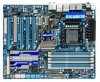
... 2 SATA 6Gb/s devices Support for SATA RAID 0, and RAID 1 GIGABYTE SATA2 chip: - 1 x IDE connector supporting ATA-133/100/66/33 and up to 2 IDE devices - 2 x SATA 3Gb/s connectors (GSATA2_8, GSATA2_9) supporting up to 2 SATA 3Gb/s devices - 1-2 Product Specifications CPU Support for an Intel® Core™ i7 series processor in the LGA1366 package (Go to GIGABYTE's website for the latest CPU support list.) L3 cache varies with CPU QPI 4.8GT/s, 6.4GT/s Chipset North Bridge: Intel® X58 Express Chipset...
... 2 SATA 6Gb/s devices Support for SATA RAID 0, and RAID 1 GIGABYTE SATA2 chip: - 1 x IDE connector supporting ATA-133/100/66/33 and up to 2 IDE devices - 2 x SATA 3Gb/s connectors (GSATA2_8, GSATA2_9) supporting up to 2 SATA 3Gb/s devices - 1-2 Product Specifications CPU Support for an Intel® Core™ i7 series processor in the LGA1366 package (Go to GIGABYTE's website for the latest CPU support list.) L3 cache varies with CPU QPI 4.8GT/s, 6.4GT/s Chipset North Bridge: Intel® X58 Express Chipset...

Manual
Page 20
.../SLI-supported motherboard with your graphics cards for the power requirement) B. Current NVIDIA GPUs that support 3-Way CrossFireX technology include the Radeon HD 3800 series, Radeon HD 4800 and Radeon HD 58XX series. A power supply with sufficient power is enabled. (Note) The bridge connectors may differ by graphics cards. Connecting the Graphics Cards Step 1: Observe the steps in "1-5 Installing an Expansion Card" and install two/three CrossFireX/SLI graphics cards on the PCI Express x16 slots. (To set up a 2-Way configuration...
.../SLI-supported motherboard with your graphics cards for the power requirement) B. Current NVIDIA GPUs that support 3-Way CrossFireX technology include the Radeon HD 3800 series, Radeon HD 4800 and Radeon HD 58XX series. A power supply with sufficient power is enabled. (Note) The bridge connectors may differ by graphics cards. Connecting the Graphics Cards Step 1: Observe the steps in "1-5 Installing an Expansion Card" and install two/three CrossFireX/SLI graphics cards on the PCI Express x16 slots. (To set up a 2-Way configuration...

Manual
Page 29
...fans are not configuration jumper blocks. The black connector wire is recommended that a system fan be installed inside the chassis. 1 CPU_FAN CPU_FAN: Pin No. Pin No. Definition 1 1 GND 2 +12V 3 NC • Be sure to connect fan cables to the fan headers to this header. The motherboard supports CPU fan speed control, which requires the use of a CPU fan with color-coded power connector wires. The fan header has a foolproof insertion design. Hardware Installation 3/4/5) CPU_FAN/SYS_FAN1/SYS_FAN2/SYS_FAN3/PWR_FAN (Fan Headers) The motherboard has a 4-pin CPU fan header...
...fans are not configuration jumper blocks. The black connector wire is recommended that a system fan be installed inside the chassis. 1 CPU_FAN CPU_FAN: Pin No. Pin No. Definition 1 1 GND 2 +12V 3 NC • Be sure to connect fan cables to the fan headers to this header. The motherboard supports CPU fan speed control, which requires the use of a CPU fan with color-coded power connector wires. The fan header has a foolproof insertion design. Hardware Installation 3/4/5) CPU_FAN/SYS_FAN1/SYS_FAN2/SYS_FAN3/PWR_FAN (Fan Headers) The motherboard has a 4-pin CPU fan header...

Manual
Page 38
.... : BIOS SETUP\Q-FLASH Press the key to enter BIOS Setup or to access the Q-Flash utility in BIOS Setup. : XPRESS RECOVERY2 If you to enter BIOS Setup first. BIOS Setup - 38 - 2-1 Startup Screen The following screens may appear when the computer boots. A. To exit Boot Menu, press . Motherboard Model BIOS Version X58A-UD7 D33 . . . . : BIOS Setup : XpressRecovery2 : Boot Menu : Qflash 10/27/2009-X58-ICH10-7A89QC0IC-00 Function Keys Function Keys Function Keys: : POST SCREEN Press the key to the instructions on the Full Screen LOGO Show item on BIOS Setup settings. Note...
.... : BIOS SETUP\Q-FLASH Press the key to enter BIOS Setup or to access the Q-Flash utility in BIOS Setup. : XPRESS RECOVERY2 If you to enter BIOS Setup first. BIOS Setup - 38 - 2-1 Startup Screen The following screens may appear when the computer boots. A. To exit Boot Menu, press . Motherboard Model BIOS Version X58A-UD7 D33 . . . . : BIOS Setup : XpressRecovery2 : Boot Menu : Qflash 10/27/2009-X58-ICH10-7A89QC0IC-00 Function Keys Function Keys Function Keys: : POST SCREEN Press the key to the instructions on the Full Screen LOGO Show item on BIOS Setup settings. Note...

Manual
Page 40
... menu to configure the device boot order, advanced features available on the CPU, and the primary display adapter. Integrated Peripherals Use this menu to configure all peripheral devices, such as IDE, SATA, USB, integrated audio, and integrated LAN, etc. Power Management Setup Use this menu to configure all the power-saving functions. PC Health Status Use this menu to see information about autodetected system/CPU temperature, system voltage and fan speed, etc. Load Fail-Safe Defaults Fail-Safe defaults...
... menu to configure the device boot order, advanced features available on the CPU, and the primary display adapter. Integrated Peripherals Use this menu to configure all peripheral devices, such as IDE, SATA, USB, integrated audio, and integrated LAN, etc. Power Management Setup Use this menu to configure all the power-saving functions. PC Health Status Use this menu to see information about autodetected system/CPU temperature, system voltage and fan speed, etc. Load Fail-Safe Defaults Fail-Safe defaults...
Manual
Page 53
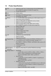
Options are: Floppy, LS120, Hard Disk, CDROM, ZIP, USB-FDD, USB-ZIP, USB-CDROM, USB-HDD, Legacy LAN, Disabled. HDD S.M.A.R.T. This feature allows your hard drive. The settings here synchronize with the settings of the SMART QuickBoot of Smart 6™. (Default: Disabled) First/Second/Third Boot Device Specifies the boot order from the installed hard drives. Password Check Specifies whether a password is present only if you enter BIOS Setup. After configuring this menu when finished. Capability Limit CPUID Max. Use the up or down arrow key to select...
Options are: Floppy, LS120, Hard Disk, CDROM, ZIP, USB-FDD, USB-ZIP, USB-CDROM, USB-HDD, Legacy LAN, Disabled. HDD S.M.A.R.T. This feature allows your hard drive. The settings here synchronize with the settings of the SMART QuickBoot of Smart 6™. (Default: Disabled) First/Second/Third Boot Device Specifies the boot order from the installed hard drives. Password Check Specifies whether a password is present only if you enter BIOS Setup. After configuring this menu when finished. Capability Limit CPUID Max. Use the up or down arrow key to select...

Manual
Page 55
... Setup Utility-Copyright (C) 1984-2009 Award Software Integrated Peripherals eXtreme Hard Drive (XHD) ICH SATA Control Mode SATA Port0-3 Native Mode USB 1.0 Controller USB 2.0 Controller USB Keyboard Function USB Mouse Function USB Storage Function Azalia Codec Onboard H/W 1394 Onboard H/W LAN1 Onboard H/W LAN2 Green LAN } SMART LAN1 } SMART LAN2 Onboard LAN1 Boot ROM Onboard LAN2 Boot ROM Onboard USB 3.0 Controller eSATA Controller [Disabled] [IDE] [Disabled] [Enabled] [Enabled] [Disabled] [Disabled] [Enabled] [Auto] [Enabled] [Enabled...
... Setup Utility-Copyright (C) 1984-2009 Award Software Integrated Peripherals eXtreme Hard Drive (XHD) ICH SATA Control Mode SATA Port0-3 Native Mode USB 1.0 Controller USB 2.0 Controller USB Keyboard Function USB Mouse Function USB Storage Function Azalia Codec Onboard H/W 1394 Onboard H/W LAN1 Onboard H/W LAN2 Green LAN } SMART LAN1 } SMART LAN2 Onboard LAN1 Boot ROM Onboard LAN2 Boot ROM Onboard USB 3.0 Controller eSATA Controller [Disabled] [IDE] [Disabled] [Enabled] [Enabled] [Disabled] [Disabled] [Enabled] [Auto] [Enabled] [Enabled...

Manual
Page 58
... hot plug. GSATA RAID Configuration (Marvell 9128 Chip, GSATA3_6/7 Connectors) Allows you to decide whether to Chapter 5, "Configuring SATA Hard Drive(s)," for the SATA controller; eSATA Ctrl Mode (JMicron JMB362 Chip, eSATA Connectors) Enables or disables RAID for the Marvell 9128 SATA controller. RAID/IDE Enables RAID for instructions on configuring a RAID array. Refer to configure the SATA controller integrated in IDE mode. IDE Disables RAID for the SATA controller and configures the SATA controller to IDE mode. (Default) AHCI Configures the SATA...
... hot plug. GSATA RAID Configuration (Marvell 9128 Chip, GSATA3_6/7 Connectors) Allows you to decide whether to Chapter 5, "Configuring SATA Hard Drive(s)," for the SATA controller; eSATA Ctrl Mode (JMicron JMB362 Chip, eSATA Connectors) Enables or disables RAID for the Marvell 9128 SATA controller. RAID/IDE Enables RAID for instructions on configuring a RAID array. Refer to configure the SATA controller integrated in IDE mode. IDE Disables RAID for the SATA controller and configures the SATA controller to IDE mode. (Default) AHCI Configures the SATA...

Manual
Page 61
...3V/+5V/+12V Displays the current system voltages. Enabled allows the CPU fan to run at full speed. (Default: Enabled) - 61 - 2-8 PC Health Status CMOS Setup Utility-Copyright (C) 1984-2009 Award Software PC Health Status Reset Case Open Status Case Opened Vcore DDR15V +3.3V +5V +12V Current CPU Temperature Current MCH Temperature Current CPU FAN Speed Current SYSTEM FAN2 Speed Current POWER FAN Speed Current SYSTEM FAN1 Speed CPU Warning Temperature CPU FAN Fail Warning CPU Smart FAN Control CPU Smart FAN Mode [Disabled] No 1.220V...
...3V/+5V/+12V Displays the current system voltages. Enabled allows the CPU fan to run at full speed. (Default: Enabled) - 61 - 2-8 PC Health Status CMOS Setup Utility-Copyright (C) 1984-2009 Award Software PC Health Status Reset Case Open Status Case Opened Vcore DDR15V +3.3V +5V +12V Current CPU Temperature Current MCH Temperature Current CPU FAN Speed Current SYSTEM FAN2 Speed Current POWER FAN Speed Current SYSTEM FAN1 Speed CPU Warning Temperature CPU FAN Fail Warning CPU Smart FAN Control CPU Smart FAN Mode [Disabled] No 1.220V...

Manual
Page 86
... X.H.D utility only supports the SATA controllers integrated in the array. ) 1. Before installing the operating system, you can go to the Application Software screen to expand its capacity. 4-8 eXtreme Hard Drive (X.H.D) With GIGABYTE eXtreme Hard Drive (X.H.D)(Note 1), users can quickly configure a RAIDready system for the Intel SATA controllers. Using GIGABYTE eXtreme Hard Drive (X.H.D) Instructions:(Note 2) Before launching X.H.D, make sure the newly added harddrive has equal or greater capacity than or equal to enable RAID...
... X.H.D utility only supports the SATA controllers integrated in the array. ) 1. Before installing the operating system, you can go to the Application Software screen to expand its capacity. 4-8 eXtreme Hard Drive (X.H.D) With GIGABYTE eXtreme Hard Drive (X.H.D)(Note 1), users can quickly configure a RAIDready system for the Intel SATA controllers. Using GIGABYTE eXtreme Hard Drive (X.H.D) Instructions:(Note 2) Before launching X.H.D, make sure the newly added harddrive has equal or greater capacity than or equal to enable RAID...

Manual
Page 97
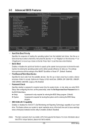
... end to the hard drive. Then connect the power connector from the exact settings for RAID. In BIOS Setup, go to RAID/IDE CMOS Setup Utility-Copyright (C) 1984-2009 Award Software Integrated Peripherals eSATA Controller eSATA Ctrl Mode GSATA 6_7/IDE Controller GSATA 6_7/IDE Ctrl Mode GSATA RAID Configuration GSATA 8_9/IDE Controller GSATA 8_9/IDE Ctrl Mode [Enabled] [RAID] [Enabled] [IDE] [Press Enter] [Enabled] [RAID/IDE] Item Help Menu Level Move Enter: Select F5: Previous Values +/-/PU/PD: Value F10: Save F6: Fail-Safe Defaults Figure 1 ESC...
... end to the hard drive. Then connect the power connector from the exact settings for RAID. In BIOS Setup, go to RAID/IDE CMOS Setup Utility-Copyright (C) 1984-2009 Award Software Integrated Peripherals eSATA Controller eSATA Ctrl Mode GSATA 6_7/IDE Controller GSATA 6_7/IDE Ctrl Mode GSATA RAID Configuration GSATA 8_9/IDE Controller GSATA 8_9/IDE Ctrl Mode [Enabled] [RAID] [Enabled] [IDE] [Press Enter] [Enabled] [RAID/IDE] Item Help Menu Level Move Enter: Select F5: Previous Values +/-/PU/PD: Value F10: Save F6: Fail-Safe Defaults Figure 1 ESC...

Manual
Page 103
... the hard drive. Make sure GSATA 6_7/IDE Cntroller under the Integrated Peripherals menu is required during the POST (Power-On Self-Test). Then set GSATA 6_7/IDE Ctrl Mode to IDE or AHCI, depending on your power supply to available SATA port on the motherboard. The actual BIOS Setup menu options you will see shall depend on the GSATA RAID Configuration item (Figure 1) to create RAID. Then connect the power connector from the exact settings for...
... the hard drive. Make sure GSATA 6_7/IDE Cntroller under the Integrated Peripherals menu is required during the POST (Power-On Self-Test). Then set GSATA 6_7/IDE Ctrl Mode to IDE or AHCI, depending on your power supply to available SATA port on the motherboard. The actual BIOS Setup menu options you will see shall depend on the GSATA RAID Configuration item (Figure 1) to create RAID. Then connect the power connector from the exact settings for...

Manual
Page 108
... motherboard driver disk to \win64 for copying the Windows 64-bit driver. For installing Windows Vista, you need to install the SATA controller driver during the Windows setup process. See the instructions below about how to a floppy disk. In MS-DOS mode: Prepare a startup disk that has CD-ROM support and a blank formatted floppy disk. sume that the drive letter for your optical drive is /are configured to RAID/AHCI mode, you also can copy the SATA controller driver from \win32 to a USB flash drive...
... motherboard driver disk to \win64 for copying the Windows 64-bit driver. For installing Windows Vista, you need to install the SATA controller driver during the Windows setup process. See the instructions below about how to a floppy disk. In MS-DOS mode: Prepare a startup disk that has CD-ROM support and a blank formatted floppy disk. sume that the drive letter for your optical drive is /are configured to RAID/AHCI mode, you also can copy the SATA controller driver from \win32 to a USB flash drive...
Manual
Page 110
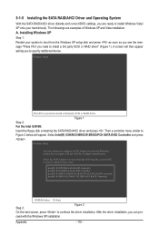
... boot from the following list, or press ESC to return to install a third party SCSI or RAID driver. Installing Windows XP Step 1: Restart your hard drive(s). Intel(R) ICH7R/DH SATA RAID Controller Intel(R) ICH7MDH SATA RAID Controller Intel(R) ICH8R/ICH9R/ICH10R/DO/PCH SATA RAID Controller Intel(R) ICH8M-E/ICH9M-E/PCHM SATA RAID Controller ENTER=Select F3=Exit Step 3: Figure 2 On the next screen, press to configure a SCSI Adapter for use with the Windows XP installation. ceed with Windows, using a device support disk...
... boot from the following list, or press ESC to return to install a third party SCSI or RAID driver. Installing Windows XP Step 1: Restart your hard drive(s). Intel(R) ICH7R/DH SATA RAID Controller Intel(R) ICH7MDH SATA RAID Controller Intel(R) ICH8R/ICH9R/ICH10R/DO/PCH SATA RAID Controller Intel(R) ICH8M-E/ICH9M-E/PCHM SATA RAID Controller ENTER=Select F3=Exit Step 3: Figure 2 On the next screen, press to configure a SCSI Adapter for use with the Windows XP installation. ceed with Windows, using a device support disk...

Manual
Page 111
... previous screen. Windows Setup You have chosen to configure a SCSI Adapter for use with Windows, using a device support disk provided by an adapter manufacturer. Select the SCSI Adapter you want from the following list, or press ESC to return to be installed (Figure 4). Appendix For the JMicron JMB362/GIGABYTE SATA2: Insert the floppy disk containing the SATA RAID/AHCI driver and press . Then a controller menu similar to Figure 3 below will display two drivers...
... previous screen. Windows Setup You have chosen to configure a SCSI Adapter for use with Windows, using a device support disk provided by an adapter manufacturer. Select the SCSI Adapter you want from the following list, or press ESC to return to be installed (Figure 4). Appendix For the JMicron JMB362/GIGABYTE SATA2: Insert the floppy disk containing the SATA RAID/AHCI driver and press . Then a controller menu similar to Figure 3 below will display two drivers...

Manual
Page 131
...the motherboard battery in Chapter 1 to short the jumper to the instructions on the computer name and select Scan for "onboard HD audio driver." For more FAQs for High Definition Audio has been installed successfully (check in the BIOS Setup program. A: The following Award BIOS beep code descriptions may help you identify possible computer problems. (For reference only.) 1 short: System boots successfully 1 long, 3 short: Keyboard error 2 short: CMOS setting error 1 long, 9 short: BIOS ROM error 1 long, 1 short: Memory or motherboard error Continuous long beeps: Graphics card not...
...the motherboard battery in Chapter 1 to short the jumper to the instructions on the computer name and select Scan for "onboard HD audio driver." For more FAQs for High Definition Audio has been installed successfully (check in the BIOS Setup program. A: The following Award BIOS beep code descriptions may help you identify possible computer problems. (For reference only.) 1 short: System boots successfully 1 long, 3 short: Keyboard error 2 short: CMOS setting error 1 long, 9 short: BIOS ROM error 1 long, 1 short: Memory or motherboard error Continuous long beeps: Graphics card not...

Manual
Page 136
... all PCI ROMs (except VGA) 1. i.e. Switch back to items described in Setup is pressed to text mode NET PC: Build SYSID structure 1. Call chipset power management hook 2. not until this POST stage can users enter the CMOS setup utility Reset keyboard is Early_Reset_KB is not defined Initialize PS/2 Mouse Prepare memory size information for Trend Anti-Virus code Appendix - 136 - Set up ACPI table at top of IRQs Read HDD boot sector information...
... all PCI ROMs (except VGA) 1. i.e. Switch back to items described in Setup is pressed to text mode NET PC: Build SYSID structure 1. Call chipset power management hook 2. not until this POST stage can users enter the CMOS setup utility Reset keyboard is Early_Reset_KB is not defined Initialize PS/2 Mouse Prepare memory size information for Trend Anti-Virus code Appendix - 136 - Set up ACPI table at top of IRQs Read HDD boot sector information...


