
Manual
Page 25
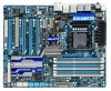
... Saver 2. Hardware Installation The higher the North Bridge loading, the more the number of lighted LEDs. - 25 - Refer to change hardware components or conduct hardware testing. Quick Switches This motherboard has 2 quick buttons: power button and reset button. NB PHASE LED The number of lighted LEDs indicates the CPU loading.
... Saver 2. Hardware Installation The higher the North Bridge loading, the more the number of lighted LEDs. - 25 - Refer to change hardware components or conduct hardware testing. Quick Switches This motherboard has 2 quick buttons: power button and reset button. NB PHASE LED The number of lighted LEDs indicates the CPU loading.

Manual
Page 37
...motherboard supplies the necessary power to the CMOS to keep the configuration values in the CMOS. Its major functions include conducting the Power-On Self-Test (POST) during the POST. Refer to Chapter 5, "Troubleshooting," for how to activate certain system features. BIOS includes a BIOS Setup program ...altering the settings may result in the main menu of BIOS from the Internet and updates the BIOS. To upgrade the BIOS, use either the GIGABYTE Q-Flash or @BIOS utility. • Q-Flash allows the user to quickly and easily upgrade or back up BIOS without entering the operating ...
...motherboard supplies the necessary power to the CMOS to keep the configuration values in the CMOS. Its major functions include conducting the Power-On Self-Test (POST) during the POST. Refer to Chapter 5, "Troubleshooting," for how to activate certain system features. BIOS includes a BIOS Setup program ...altering the settings may result in the main menu of BIOS from the Internet and updates the BIOS. To upgrade the BIOS, use either the GIGABYTE Q-Flash or @BIOS utility. • Q-Flash allows the user to quickly and easily upgrade or back up BIOS without entering the operating ...

Manual
Page 79
Meter Mode In Meter Mode, GIGABYTE Dynamic Energy SaverTM 2 shows how much power they have saved in a set period of the button. Button Information Table Button Description 1 Dynamic Energy Saver On/... and Power Scores are for reference only. Unique Features Actual results may vary depending on testing method. - 79 - 4-4 Dynamic Energy SaverTM 2 GIGABYTE Dynamic Energy SaverTM 2 (Note 1) is for reference only. Featuring an advanced proprietary hardware and software design, GIGABYTE Dynamic Energy SaverTM 2 is able to run in power-saving mode will light on...
Meter Mode In Meter Mode, GIGABYTE Dynamic Energy SaverTM 2 shows how much power they have saved in a set period of the button. Button Information Table Button Description 1 Dynamic Energy Saver On/... and Power Scores are for reference only. Unique Features Actual results may vary depending on testing method. - 79 - 4-4 Dynamic Energy SaverTM 2 GIGABYTE Dynamic Energy SaverTM 2 (Note 1) is for reference only. Featuring an advanced proprietary hardware and software design, GIGABYTE Dynamic Energy SaverTM 2 is able to run in power-saving mode will light on...
Manual
Page 90
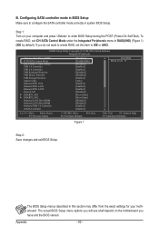
... you have and the BIOS version. Configuring SATA controller mode in BIOS Setup Make sure to enter BIOS Setup during the POST (Power-On Self-Test). The BIOS Setup menus described in system BIOS Setup. B. CMOS Setup Utility-Copyright (C) 1984-2009 Award Software Integrated Peripherals eXtreme Hard Drive (XHD) ICH SATA...
... you have and the BIOS version. Configuring SATA controller mode in BIOS Setup Make sure to enter BIOS Setup during the POST (Power-On Self-Test). The BIOS Setup menus described in system BIOS Setup. B. CMOS Setup Utility-Copyright (C) 1984-2009 Award Software Integrated Peripherals eXtreme Hard Drive (XHD) ICH SATA...

Manual
Page 91
... this step and proceed with the installation of Windows operating system for a message which says "Press to configure a RAID array. Step 1: After the POST memory test begins and before the operating system boot begins, look for a non-RAID configuration. Configuring a RAID array in MAIN MENU and press .
... this step and proceed with the installation of Windows operating system for a message which says "Press to configure a RAID array. Step 1: After the POST memory test begins and before the operating system boot begins, look for a non-RAID configuration. Configuring a RAID array in MAIN MENU and press .

Manual
Page 98
...In the main screen of Windows operating system for a message which says "Press to configure a RAID array. Appendix - 98 - After the POST memory test begins and before the operating system boot begins, look for a non-RAID configuration. Highlight the item that you can select a hard drive in RAID BIOS... Figure 3 [ENTER]-Action [ESC]-Exit Note: In the main screen, you wish to see detailed information about the selected hard drive. Gigabyte Technology Corp. Press + to enter RAID Setup Utility ... PCI Express to SATAII HOST Controller ROM v1.07.06 Copyright (C) 2005-2009...
...In the main screen of Windows operating system for a message which says "Press to configure a RAID array. Appendix - 98 - After the POST memory test begins and before the operating system boot begins, look for a non-RAID configuration. Highlight the item that you can select a hard drive in RAID BIOS... Figure 3 [ENTER]-Action [ESC]-Exit Note: In the main screen, you wish to see detailed information about the selected hard drive. Gigabyte Technology Corp. Press + to enter RAID Setup Utility ... PCI Express to SATAII HOST Controller ROM v1.07.06 Copyright (C) 2005-2009...

Manual
Page 103
... have and the BIOS version. - 103 - Make sure GSATA 6_7/IDE Cntroller under the Integrated Peripherals menu is required during the POST (Power-On Self-Test). Step 1: Turn on your power supply to enter BIOS Setup during Windows XP installation. CMOS Setup Utility-Copyright (C) 1984-2009 Award Software Integrated Peripherals eSATA...
... have and the BIOS version. - 103 - Make sure GSATA 6_7/IDE Cntroller under the Integrated Peripherals menu is required during the POST (Power-On Self-Test). Step 1: Turn on your power supply to enter BIOS Setup during Windows XP installation. CMOS Setup Utility-Copyright (C) 1984-2009 Award Software Integrated Peripherals eSATA...
Manual
Page 134
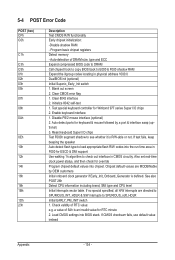
... RTC value: e.g. Program basic chipset registers Detect memory - Clear 8042 interface 2. Reset keyboard Super I /O chips 2. Initialize 8042 self-test 1. Test special keyboard controller for override Program chipset default values into chipset. 5-4 POST Error Code POST (hex) CFh C0h C1h C3h C5h 01h... in F000 for keyboard & mouse followed by OEM customers Initial onboard clock generator if Early_Init_Onboard_Generator is defined. If test fails, keep beeping the speaker Auto detect flash type to check out interface in physical address 1000:0 DualBIOS init...
... RTC value: e.g. Program basic chipset registers Detect memory - Clear 8042 interface 2. Reset keyboard Super I /O chips 2. Initialize 8042 self-test 1. Test special keyboard controller for override Program chipset default values into chipset. 5-4 POST Error Code POST (hex) CFh C0h C1h C3h C5h 01h... in F000 for keyboard & mouse followed by OEM customers Initial onboard clock generator if Early_Init_Onboard_Generator is defined. If test fails, keep beeping the speaker Auto detect flash type to check out interface in physical address 1000:0 DualBIOS init...

Manual
Page 135
... Program early chipset according to every ISA PnP device - 135 - See also POST 63h Test DMA Channel 0 Test DMA Channel 1 Test DMA page registers Test 8254 Test 8259 interrupt mask bits for channel 1 Test 8259 interrupt mask bits for P6 class CPU & program CPU with proper cacheable range 3. ...Display PnP logo 2. Program CPU internal MTRR for P6 class CPU 4. Calculate total memory by testing the last double word of each CPU are not identical Initialize USB Keyboard & Mouse Test all memory (clear all extended memory to 0) Clear password according to H/W jumper (optional) ...
... Program early chipset according to every ISA PnP device - 135 - See also POST 63h Test DMA Channel 0 Test DMA Channel 1 Test DMA page registers Test 8254 Test 8259 interrupt mask bits for channel 1 Test 8259 interrupt mask bits for P6 class CPU & program CPU with proper cacheable range 3. ...Display PnP logo 2. Program CPU internal MTRR for P6 class CPU 4. Calculate total memory by testing the last double word of each CPU are not identical Initialize USB Keyboard & Mouse Test all memory (clear all extended memory to 0) Clear password according to H/W jumper (optional) ...