
Manual
Page 33
...normal restart. • CI (Chassis Intrusion Header, Gray): Connects to the reset switch on the chassis that can detect if the chassis cover has been removed. When connecting your system using the power switch (refer to Chapter 2, "BIOS Setup," "Power Management Setup," for information about beep codes. • HD ...problem. If a problem is in different patterns to the power switch on the chassis front panel. S1 Blinking tem is detected, the BIOS may issue beeps in S1 sleep state. The LED is off your chassis front panel module to this header according to the power ...
...normal restart. • CI (Chassis Intrusion Header, Gray): Connects to the reset switch on the chassis that can detect if the chassis cover has been removed. When connecting your system using the power switch (refer to Chapter 2, "BIOS Setup," "Power Management Setup," for information about beep codes. • HD ...problem. If a problem is in different patterns to the power switch on the chassis front panel. S1 Blinking tem is detected, the BIOS may issue beeps in S1 sleep state. The LED is off your chassis front panel module to this header according to the power ...

Manual
Page 37
...failure to boot. To upgrade the BIOS, use either the GIGABYTE Q-Flash or @BIOS utility. • Q-Flash allows the user to quickly and easily upgrade or back up BIOS without entering the operating system. • @BIOS is a Windows-based utility that ...reset the board to default values. (Refer to the "Load Optimized Defaults" section in this chapter or introductions of the battery/ clearing CMOS jumper in the CMOS on . BIOS includes a BIOS Setup program that searches and downloads the latest version of BIOS from the Internet and updates the BIOS. Chapter 2 BIOS Setup BIOS...
...failure to boot. To upgrade the BIOS, use either the GIGABYTE Q-Flash or @BIOS utility. • Q-Flash allows the user to quickly and easily upgrade or back up BIOS without entering the operating system. • @BIOS is a Windows-based utility that ...reset the board to default values. (Refer to the "Load Optimized Defaults" section in this chapter or introductions of the battery/ clearing CMOS jumper in the CMOS on . BIOS includes a BIOS Setup program that searches and downloads the latest version of BIOS from the Internet and updates the BIOS. Chapter 2 BIOS Setup BIOS...

Manual
Page 41
...>>>>> Channel C x CAS Latency Time - Auto x Command Rate(CMD) - If this occurs, clear the CMOS values and reset the board to default values.) (Note 1) This item appears only if you install a CPU that supports this feature. (Note ... CPU, chipset, or memory and reduce the useful life of these components. Auto x tRCD - This page is dependent on your overall system configurations. BIOS Setup Auto x Command Rate(CMD) - Auto x tRAS - Auto } Advanced DRAM Features [Press Enter] Voltage Types Normal Current Load-Line Calibration ...
...>>>>> Channel C x CAS Latency Time - Auto x Command Rate(CMD) - If this occurs, clear the CMOS values and reset the board to default values.) (Note 1) This item appears only if you install a CPU that supports this feature. (Note ... CPU, chipset, or memory and reduce the useful life of these components. Auto x tRCD - This page is dependent on your overall system configurations. BIOS Setup Auto x Command Rate(CMD) - Auto x tRAS - Auto } Advanced DRAM Features [Press Enter] Voltage Types Normal Current Load-Line Calibration ...

Manual
Page 45
Enabled will allow for automated system reboot, or clear the CMOS values to reset the board to default values. (Default: Disabled) BCLK Frequency(Mhz) Allows you to adjust the amplitude of the PCI Express and North Bridge clock. >>>>> Standard ... MHz. Options are : 700mV, 800mV, 900mV (default), 1000mV. Options are : 0ps~750ps. (Default: 0ps) - 45 - The adjustable range is from 100 MHz to 150 MHz. BIOS Setup Note: If your system fails to boot after overclocking, please wait for 20 seconds to allow the BCLK Frequency(Mhz) item below to be...
Enabled will allow for automated system reboot, or clear the CMOS values to reset the board to default values. (Default: Disabled) BCLK Frequency(Mhz) Allows you to adjust the amplitude of the PCI Express and North Bridge clock. >>>>> Standard ... MHz. Options are : 700mV, 800mV, 900mV (default), 1000mV. Options are : 0ps~750ps. (Default: 0ps) - 45 - The adjustable range is from 100 MHz to 150 MHz. BIOS Setup Note: If your system fails to boot after overclocking, please wait for 20 seconds to allow the BCLK Frequency(Mhz) item below to be...

Manual
Page 61
...: Disabled) CPU Smart FAN Control Enables or disables the CPU fan speed control function. When CPU temperature exceeds the threshold, BIOS will show "No". Enabled clears the record of previous chassis intrusion status and the Case Opened field will emit warning sound....speed. (Default: Enabled) - 61 - 2-8 PC Health Status CMOS Setup Utility-Copyright (C) 1984-2009 Award Software PC Health Status Reset Case Open Status Case Opened Vcore DDR15V +3.3V +5V +12V Current CPU Temperature Current MCH Temperature Current CPU FAN Speed Current SYSTEM...
...: Disabled) CPU Smart FAN Control Enables or disables the CPU fan speed control function. When CPU temperature exceeds the threshold, BIOS will show "No". Enabled clears the record of previous chassis intrusion status and the Case Opened field will emit warning sound....speed. (Default: Enabled) - 61 - 2-8 PC Health Status CMOS Setup Utility-Copyright (C) 1984-2009 Award Software PC Health Status Reset Case Open Status Case Opened Vcore DDR15V +3.3V +5V +12V Current CPU Temperature Current MCH Temperature Current CPU FAN Speed Current SYSTEM...

Manual
Page 75
The following procedure assumes that you sure to Drive Enter : Run hi:Move ESC:Reset F10:Power Off Total size : 0 Free size : 0 3. Step 1: 1. Make sure the BIOS update file matches your motherboard model. The monitor will display the update process. • Do not turn off ...Please SparevsesBaInOySketoy Dtoricvoentinue Enter : Run hi:Move ESC:Reset F10:Power Off - 75 - Q-Flash Utility v2.09 Flash Type/Size MXIC 25L1605A 1M Keep DMI Data Enable !L! Updating the BIOS When updating the BIOS, choose the location where the BIOS file is updat- Q-Flash Utility v2.09 ...
The following procedure assumes that you sure to Drive Enter : Run hi:Move ESC:Reset F10:Power Off Total size : 0 Free size : 0 3. Step 1: 1. Make sure the BIOS update file matches your motherboard model. The monitor will display the update process. • Do not turn off ...Please SparevsesBaInOySketoy Dtoricvoentinue Enter : Run hi:Move ESC:Reset F10:Power Off - 75 - Q-Flash Utility v2.09 Flash Type/Size MXIC 25L1605A 1M Keep DMI Data Enable !L! Updating the BIOS When updating the BIOS, choose the location where the BIOS file is updat- Q-Flash Utility v2.09 ...

Manual
Page 80
...Note 1) Before using the Dynamic Energy SaverTM 2 function, make sure the CPU Enhanced Halt (C1E) and CPU EIST Function items in the BIOS Setup program are able to see how much total power savings they have accumulated in a set to work with Dynamic Energy Saver enabled) (...3-Level Power Saving Switch (Default:1) (Note 2) 10 Advanced Settings 11 Close (Application will enter Stealth Mode) 12 Minimize (Application will automatically reset when the total power saving reaches 99999999 Watts. Total Mode In Total Mode, users are set period of time since activating Dynamic Energy SaverTM ...
...Note 1) Before using the Dynamic Energy SaverTM 2 function, make sure the CPU Enhanced Halt (C1E) and CPU EIST Function items in the BIOS Setup program are able to see how much total power savings they have accumulated in a set to work with Dynamic Energy Saver enabled) (...3-Level Power Saving Switch (Default:1) (Note 2) 10 Advanced Settings 11 Close (Application will enter Stealth Mode) 12 Minimize (Application will automatically reset when the total power saving reaches 99999999 Watts. Total Mode In Total Mode, users are set period of time since activating Dynamic Energy SaverTM ...

Manual
Page 91
... the operating system boot begins, look for a non-RAID configuration. Press + to enter Configuration Utility" (Figure 2). Create RAID Volume 2. Reset Disks to configure a RAID array. Skip this step and proceed with the installation of Windows operating system for a message which says "Press ....7GB Type/Status(Vol ID) Non-RAID Disk Non-RAID Disk Press to create a RAID array, select Create RAID Volume in RAID BIOS Enter the RAID BIOS setup utility to Non-RAID 4. Figure 2 Step 2: After you want to enter Configuration Utility.. Delete RAID Volume 5. All Rights Reserved...
... the operating system boot begins, look for a non-RAID configuration. Press + to enter Configuration Utility" (Figure 2). Create RAID Volume 2. Reset Disks to configure a RAID array. Skip this step and proceed with the installation of Windows operating system for a message which says "Press ....7GB Type/Status(Vol ID) Non-RAID Disk Non-RAID Disk Press to create a RAID array, select Create RAID Volume in RAID BIOS Enter the RAID BIOS setup utility to Non-RAID 4. Figure 2 Step 2: After you want to enter Configuration Utility.. Delete RAID Volume 5. All Rights Reserved...

Manual
Page 93
...111.7GB 111.7GB Type/Status(Vol ID) Member Disk(0) Member Disk(0) [hi]-Select [ESC]-Exit Figure 7 [ENTER]-Select Menu To exit the RAID BIOS utility, press or select 5. All Rights Reserved. [ CREATE VOLUME MENU ] Name : Volume0 RAID Level : RAID0(Stripe) Disks : Select Disks Strip ...When prompted to confirm whether to create this volume? (Y/N) : Press ENTER to Non-RAID 4. Step 5: Enter the array capacity and press . Reset Disks to create the specified volume. [hi]-Change [TAB]-Next [ESC]-Previous Menu Figure 6 [ENTER]-Select When completed, you can see detailed ...
...111.7GB 111.7GB Type/Status(Vol ID) Member Disk(0) Member Disk(0) [hi]-Select [ESC]-Exit Figure 7 [ENTER]-Select Menu To exit the RAID BIOS utility, press or select 5. All Rights Reserved. [ CREATE VOLUME MENU ] Name : Volume0 RAID Level : RAID0(Stripe) Disks : Select Disks Strip ...When prompted to confirm whether to create this volume? (Y/N) : Press ENTER to Non-RAID 4. Step 5: Enter the array capacity and press . Reset Disks to create the specified volume. [hi]-Change [TAB]-Next [ESC]-Previous Menu Figure 6 [ENTER]-Select When completed, you can see detailed ...
Manual
Page 134
...16h 18h 1Bh 1Dh 23h Description Test CMOS R/W functionality Early chipset initialization: -Disable shadow RAM - Clear 8042 interface 2. Reset keyboard Super I /O chips 2. Auto-detection of RTC value: e.g. Initialize 8042 self-test 1. If test fails, keep... OEM customers Initial onboard clock generator if Early_Init_Onboard_Generator is an invalid value for override Program chipset default values into BIOS stack. Load CMOS settings into chipset. Chipset default values are directed to SPURIOUS_INT_HDLR & S/W interrupts to E000 ...
...16h 18h 1Bh 1Dh 23h Description Test CMOS R/W functionality Early chipset initialization: -Disable shadow RAM - Clear 8042 interface 2. Reset keyboard Super I /O chips 2. Auto-detection of RTC value: e.g. Initialize 8042 self-test 1. If test fails, keep... OEM customers Initial onboard clock generator if Early_Init_Onboard_Generator is an invalid value for override Program chipset default values into BIOS stack. Load CMOS settings into chipset. Chipset default values are directed to SPURIOUS_INT_HDLR & S/W interrupts to E000 ...

Manual
Page 135
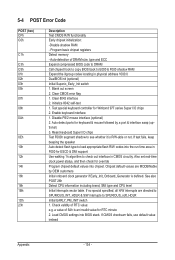
... 27h 29h 2Bh 2Dh 33h 35h 37h 39h 3Ch 3Eh 40h 43h 47h 49h 4Eh 50h 52h 53h 55h 57h Description Prepare BIOS resource map for P6 class CPU 4. Init onboard PWM 3. Early ISA PnP initialization - Assign memory & I /O chips....proper cacheable range 3. Put information on screen display, including Award title, CPU type, CPU speed, full screen logo Reset keyboard if Early_Reset_KB is not defined Onboard clock generator initialization. Calculate total memory by testing the last double word of each...
... 27h 29h 2Bh 2Dh 33h 35h 37h 39h 3Ch 3Eh 40h 43h 47h 49h 4Eh 50h 52h 53h 55h 57h Description Prepare BIOS resource map for P6 class CPU 4. Init onboard PWM 3. Early ISA PnP initialization - Assign memory & I /O chips....proper cacheable range 3. Put information on screen display, including Award title, CPU type, CPU speed, full screen logo Reset keyboard if Early_Reset_KB is not defined Onboard clock generator initialization. Calculate total memory by testing the last double word of each...


