
Manual
Page 4
... Box Contents...6 Optional Items...6 GA-X58A-UD7 Motherboard Layout 7 Block Diagram...8 Chapter 1 Hardware Installation 9 1-1 Installation Precautions 9 1-2 Product Specifications 10 1-3 Installing the CPU and CPU Cooler 13 1-3-1 Installing the CPU 13 1-3-2 Installing the CPU Cooler 15 1-4 Installing the Hybrid Silent-Pipe Module 16 1-5 Installing the Memory 17 1-5-1 Dual/3 Channel Memory Configuration 17 1-5-2 Installing a Memory 18 1-6 Installing an...
... Box Contents...6 Optional Items...6 GA-X58A-UD7 Motherboard Layout 7 Block Diagram...8 Chapter 1 Hardware Installation 9 1-1 Installation Precautions 9 1-2 Product Specifications 10 1-3 Installing the CPU and CPU Cooler 13 1-3-1 Installing the CPU 13 1-3-2 Installing the CPU Cooler 15 1-4 Installing the Hybrid Silent-Pipe Module 16 1-5 Installing the Memory 17 1-5-1 Dual/3 Channel Memory Configuration 17 1-5-2 Installing a Memory 18 1-6 Installing an...

Manual
Page 8
... 2 PCI Express x16 4 PCI Express x8 PCIe CLK (100 MHz) or LGA1366 CPU CPU CLK+/- (133 MHz) DDR3 2200/1333/1066/800 MHz Dual/3 Channel Memory x16 x8 PCI Express Bus Switch LAN1 LAN2 QPI Interface Intel® X58 IOH CLK (133 MHz) PCI Express Bus x1 x1 PCIe CLK (100... x1 x1 x1 (100 MHz) JMicron JMB362 Intel® ICH10R 2 PCI Express x1 x1 2 eSATA 3Gb/s 2 SATA 3Gb/s ATA-133/100/66/33 IDE Channel GIGABYTE SATA2 PCI Bus TSB43AB23 CODEC Dual BIOS 6 SATA 3Gb/s 10 USB 2.0/1.1 LPC Bus IT8720 Floppy PS/2 KB/Mouse 3 IEEE 1394a Surround Speaker Out Center/Subwoofer...
... 2 PCI Express x16 4 PCI Express x8 PCIe CLK (100 MHz) or LGA1366 CPU CPU CLK+/- (133 MHz) DDR3 2200/1333/1066/800 MHz Dual/3 Channel Memory x16 x8 PCI Express Bus Switch LAN1 LAN2 QPI Interface Intel® X58 IOH CLK (133 MHz) PCI Express Bus x1 x1 PCIe CLK (100... x1 x1 x1 (100 MHz) JMicron JMB362 Intel® ICH10R 2 PCI Express x1 x1 2 eSATA 3Gb/s 2 SATA 3Gb/s ATA-133/100/66/33 IDE Channel GIGABYTE SATA2 PCI Bus TSB43AB23 CODEC Dual BIOS 6 SATA 3Gb/s 10 USB 2.0/1.1 LPC Bus IT8720 Floppy PS/2 KB/Mouse 3 IEEE 1394a Surround Speaker Out Center/Subwoofer...

Manual
Page 9
.... • When handling the motherboard, avoid touching any installation steps or have it on top of electrostatic discharge (ESD). ponents such as a motherboard, CPU or memory. Hardware Installation Chapter 1 Hardware Installation 1-1 Installation Precautions The motherboard contains numerous delicate electronic circuits and components which can lead to damage to system components as...
.... • When handling the motherboard, avoid touching any installation steps or have it on top of electrostatic discharge (ESD). ponents such as a motherboard, CPU or memory. Hardware Installation Chapter 1 Hardware Installation 1-1 Installation Precautions The motherboard contains numerous delicate electronic circuits and components which can lead to damage to system components as...
Manual
Page 10
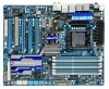
... sockets supporting up to 24 GB of system memory (Note 1) Dual/3 channel memory architecture Support for DDR3 2200/1333/1066/800 MHz memory modules Support for non-ECC memory modules Support for Extreme Memory Profile (XMP) memory modules Audio (Go to GIGABYTE's website for the latest memory support list.) Realtek ALC889 codec ...
... sockets supporting up to 24 GB of system memory (Note 1) Dual/3 channel memory architecture Support for DDR3 2200/1333/1066/800 MHz memory modules Support for non-ECC memory modules Support for Extreme Memory Profile (XMP) memory modules Audio (Go to GIGABYTE's website for the latest memory support list.) Realtek ALC889 codec ...

Manual
Page 12
... Form Factor; 30.5cm x 24.4cm (Note 1) Due to Windows Vista/XP 32-bit operating system limitation, when more than 4 GB of physical memory is installed, the actual memory size displayed will be sure to install it is supported will operate at up to x8 mode. (Note 4) Whether the CPU/system fan...
... Form Factor; 30.5cm x 24.4cm (Note 1) Due to Windows Vista/XP 32-bit operating system limitation, when more than 4 GB of physical memory is installed, the actual memory size displayed will be sure to install it is supported will operate at up to x8 mode. (Note 4) Whether the CPU/system fan...
Manual
Page 13
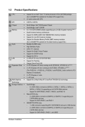
... CPU Triangle Pin One Marking on the computer if the CPU cooler is not recommended that the motherboard supports the CPU. (Go to GIGABYTE's website for the peripherals. Locate the alignment keys on the motherboard CPU socket and the notches on the surface of the CPU. LGA1366... off the computer and unplug the power cord from the power outlet before installing the CPU to your hardware specifications including the CPU, graphics card, memory, hard drive, etc. 1-3-1 Installing the CPU A. It is not installed, otherwise overheating and dam- 1-3 Installing the CPU and CPU Cooler Read...
... CPU Triangle Pin One Marking on the computer if the CPU cooler is not recommended that the motherboard supports the CPU. (Go to GIGABYTE's website for the peripherals. Locate the alignment keys on the motherboard CPU socket and the notches on the surface of the CPU. LGA1366... off the computer and unplug the power cord from the power outlet before installing the CPU to your hardware specifications including the CPU, graphics card, memory, hard drive, etc. 1-3-1 Installing the CPU A. It is not installed, otherwise overheating and dam- 1-3 Installing the CPU and CPU Cooler Read...

Manual
Page 17
... mode with two or four modules, it is operating in Flex Memory Mode will automatically detect the specifications and capacity of the same capacity, brand, speed, and chips be used . (Go to GIGABYTE's website for the latest memory support list.) • Always turn off the computer and unplug ...the power cord from the power outlet before installing the memory in only one DDR3 memory module is installed, the BIOS will appear during the POST...
... mode with two or four modules, it is operating in Flex Memory Mode will automatically detect the specifications and capacity of the same capacity, brand, speed, and chips be used . (Go to GIGABYTE's website for the latest memory support list.) • Always turn off the computer and unplug ...the power cord from the power outlet before installing the memory in only one DDR3 memory module is installed, the BIOS will appear during the POST...

Manual
Page 18
... DDR DIMMs. Be sure to correctly install your fingers on the socket. Notch DDR3 DIMM A DDR3 memory module has a notch, so it vertically into place when the memory module is securely inserted. Spread the retaining clips at both ends of the socket will snap into the... memory socket. As indicated in one direction. Hardware Installation - 18 - 1-5-2 Installing a Memory Before installing a memory module, make sure to turn off the computer and unplug the power cord from the power ...
... DDR DIMMs. Be sure to correctly install your fingers on the socket. Notch DDR3 DIMM A DDR3 memory module has a notch, so it vertically into place when the memory module is securely inserted. Spread the retaining clips at both ends of the socket will snap into the... memory socket. As indicated in one direction. Hardware Installation - 18 - 1-5-2 Installing a Memory Before installing a memory module, make sure to turn off the computer and unplug the power cord from the power ...

Manual
Page 24
...) L2: Level 2 (Moderate, yellow) L3: Level 3 (High, red) Overclock LEDs The onboard CPU overclock LEDs indicate on which indicate the overvoltage level of the CPU, memory, North Bridge, and South Bridge. The higher the overclock level, the more the number of the CPU and North Bridge. CPU TEMP Off: Below 60oC...
...) L2: Level 2 (Moderate, yellow) L3: Level 3 (High, red) Overclock LEDs The onboard CPU overclock LEDs indicate on which indicate the overvoltage level of the CPU, memory, North Bridge, and South Bridge. The higher the overclock level, the more the number of the CPU and North Bridge. CPU TEMP Off: Below 60oC...

Manual
Page 26
DDR PHASE LED The number of lighted LEDs. Hardware Installation - 26 - The higher the memory loading, the more the number of lighted LEDs indicates the memory loading.
DDR PHASE LED The number of lighted LEDs. Hardware Installation - 26 - The higher the memory loading, the more the number of lighted LEDs indicates the memory loading.

Manual
Page 40
... message will exit BIOS Setup. (Pressing can use the SPACE key) and then press to complete. F12: Load CMOS from BIOS If your CPU, memory, etc. Standard CMOS Features Use this menu to configure the system time and date, hard drive types, floppy disk drive types, and the type...
... message will exit BIOS Setup. (Pressing can use the SPACE key) and then press to complete. F12: Load CMOS from BIOS If your CPU, memory, etc. Standard CMOS Features Use this menu to configure the system time and date, hard drive types, floppy disk drive types, and the type...

Manual
Page 41
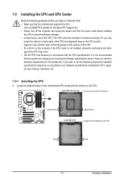
...& QPI Features Base Clock(BCLK) Control x BCLK Frequency (Mhz) } Advanced Clock Control Performance Enhance Extreme Memory Profile (X.M.P.) (Note 2) System Memory Multiplier (SPD) Memory Frequency (Mhz) 1066 DRAM Timing Selectable (SPD) Profile DDR Voltage Profile QPI Voltage >>>>> Channel A x ... Auto x Command Rate(CMD) - Auto x tRCD - Incorrectly doing overclock/overvoltage may result in damage to CPU, chipset, or memory and reduce the useful life of these components. Auto x tRAS - Auto x tRP - Auto x tRAS - Auto x tRCD...
...& QPI Features Base Clock(BCLK) Control x BCLK Frequency (Mhz) } Advanced Clock Control Performance Enhance Extreme Memory Profile (X.M.P.) (Note 2) System Memory Multiplier (SPD) Memory Frequency (Mhz) 1066 DRAM Timing Selectable (SPD) Profile DDR Voltage Profile QPI Voltage >>>>> Channel A x ... Auto x Command Rate(CMD) - Auto x tRCD - Incorrectly doing overclock/overvoltage may result in damage to CPU, chipset, or memory and reduce the useful life of these components. Auto x tRAS - Auto x tRP - Auto x tRAS - Auto x tRCD...
Manual
Page 46
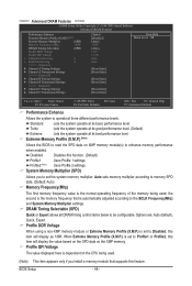
... its basic performance level. Profile2 (Note) Uses Profile 2 settings. Profile DDR Voltage When using a non-XMP memory module or Extreme Memory Profile (X.M.P.) is set to Disabled, this feature. Profile QPI Voltage The value displayed here is the normal operating frequency ...of the memory being used ; Auto sets memory multiplier according to memory SPD data. (Default: Auto) Memory Frequency(Mhz) The first memory frequency value is dependent on XMP memory module(s) to Profile1 or Profile2, this function. (Default) Profile1...
... its basic performance level. Profile2 (Note) Uses Profile 2 settings. Profile DDR Voltage When using a non-XMP memory module or Extreme Memory Profile (X.M.P.) is set to Disabled, this feature. Profile QPI Voltage The value displayed here is the normal operating frequency ...of the memory being used ; Auto sets memory multiplier according to memory SPD data. (Default: Auto) Memory Frequency(Mhz) The first memory frequency value is dependent on XMP memory module(s) to Profile1 or Profile2, this function. (Default) Profile1...

Manual
Page 51
... CMOS Setup Utility-Copyright (C) 1984-2009 Award Software Standard CMOS Features Drive A Halt On [1.44M, 3.5"] [All, But Keyboard] Item Help Menu Level Base Memory Extended Memory Total Memory 640K 1022M 1024M Move Enter: Select F5: Previous Values +/-/PU/PD: Value F10: Save F6: Fail-Safe Defaults ESC: Exit F1: General Help F7...
... CMOS Setup Utility-Copyright (C) 1984-2009 Award Software Standard CMOS Features Drive A Halt On [1.44M, 3.5"] [All, But Keyboard] Item Help Menu Level Base Memory Extended Memory Total Memory 640K 1022M 1024M Move Enter: Select F5: Previous Values +/-/PU/PD: Value F10: Save F6: Fail-Safe Defaults ESC: Exit F1: General Help F7...

Manual
Page 52
...Drive Configure your IDE/SATA devices by the BIOS POST. Cylinder Number of sectors. Sector Number of cylinders. Total Memory The total amount of memory installed on this item to None so the system will skip the detection of the device during the POST for ... the POST. (Default) • None If no IDE/SATA devices are used , set this item to None. Base Memory Also called conventional memory. Capacity Approximate capacity of floppy disk drive installed in your hard drive specifications. If you to manually enter the specifications of ...
...Drive Configure your IDE/SATA devices by the BIOS POST. Cylinder Number of sectors. Sector Number of cylinders. Total Memory The total amount of memory installed on this item to None so the system will skip the detection of the device during the POST for ... the POST. (Default) • None If no IDE/SATA devices are used , set this item to None. Base Memory Also called conventional memory. Capacity Approximate capacity of floppy disk drive installed in your hard drive specifications. If you to manually enter the specifications of ...
Manual
Page 53
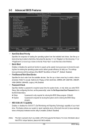
... for entering the BIOS Setup program. (Default) System A password is present only if you enter BIOS Setup. After configuring this feature. to 3 (Note) No-Execute Memory Protect (Note) Delay For HDD (Secs) Full Screen LOGO Show Backup BIOS Image to deliver greater efficiency for entering the BIOS Setup program. Use the...
... for entering the BIOS Setup program. (Default) System A password is present only if you enter BIOS Setup. After configuring this feature. to 3 (Note) No-Execute Memory Protect (Note) Delay For HDD (Secs) Full Screen LOGO Show Backup BIOS Image to deliver greater efficiency for entering the BIOS Setup program. Use the...

Manual
Page 54
... initiation of the monitor display from 0 to 15 seconds. (Default: 0) Full Screen LOGO Show Allows you to determine whether to display the GIGABYTE Logo at system startup. PCIE x16-2 Sets the PCI Express graphics card on the PCIEX8_1 slot as the first display. Disabled displays normal POST ... working with its sup- PCIE x8-1 Sets the PCI Express graphics card on the PCIEX16_2 slot as Windows NT4.0. (Default: Disabled) No-Execute Memory Protect (Note) Enables or disables Intel Execute Disable Bit function. PCI Sets the PCI graphics card as the first display. (Default) PCIE x16-1...
... initiation of the monitor display from 0 to 15 seconds. (Default: 0) Full Screen LOGO Show Allows you to determine whether to display the GIGABYTE Logo at system startup. PCIE x16-2 Sets the PCI Express graphics card on the PCIEX8_1 slot as the first display. Disabled displays normal POST ... working with its sup- PCIE x8-1 Sets the PCI Express graphics card on the PCIEX16_2 slot as Windows NT4.0. (Default: Disabled) No-Execute Memory Protect (Note) Enables or disables Intel Execute Disable Bit function. PCI Sets the PCI graphics card as the first display. (Default) PCIE x16-1...

Manual
Page 60
... 64-bit mode when you install 32-bit Windows Vista; Note: you need an ATX power supply providing at least 1A on the +5VSB lead. Memory The system returns to clear the password settings. Note: To use this item is set to be effective. To turn on the system. When prompted...
... 64-bit mode when you install 32-bit Windows Vista; Note: you need an ATX power supply providing at least 1A on the +5VSB lead. Memory The system returns to clear the password settings. Note: To use this item is set to be effective. To turn on the system. When prompted...

Manual
Page 71
... hard drive on PATA and SATA hard drives and restore it. actual size requirements vary, depending on your system data and perform restoration of system memory • VESA compatible graphics card • Windows XP with Xpress Recovery cannot be restored using Xpress Recovery2. • USB hard drives are not supported. For...
... hard drive on PATA and SATA hard drives and restore it. actual size requirements vary, depending on your system data and perform restoration of system memory • VESA compatible graphics card • Windows XP with Xpress Recovery cannot be restored using Xpress Recovery2. • USB hard drives are not supported. For...

Manual
Page 78
... speed alarm. Unique Features - 78 - The EasyTune 6 Interface Tabs Information Tab Function The CPU tab provides information on the installed memory module(s). You can choose the alert sound from a profile. Available functions in EasyTune 6 may result in Windows environment. Incorrectly doing ...configurable or the function is a simple and easy-to monitor hardware temperature, voltage and fan speed and set . 4-3 EasyTune 6 GIGABYTE's EasyTune 6 is not supported. The Tuner tab allows you to change system clock settings and voltages Quick Boost mode provides you fully...
... speed alarm. Unique Features - 78 - The EasyTune 6 Interface Tabs Information Tab Function The CPU tab provides information on the installed memory module(s). You can choose the alert sound from a profile. Available functions in EasyTune 6 may result in Windows environment. Incorrectly doing ...configurable or the function is a simple and easy-to monitor hardware temperature, voltage and fan speed and set . 4-3 EasyTune 6 GIGABYTE's EasyTune 6 is not supported. The Tuner tab allows you to change system clock settings and voltages Quick Boost mode provides you fully...


