
Manual
Page 4
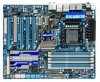
Table of Contents Box Contents...6 Optional Items...6 GA-X58A-UD7 Motherboard Layout 7 Block Diagram...8 Chapter 1 Hardware Installation 9 1-1 Installation Precautions 9 1-2 Product Specifications 10 1-3 Installing the CPU and CPU Cooler 13 1-3-1 Installing the CPU 13 1-3-2 Installing the CPU Cooler 15 1-4 Installing the Hybrid Silent-Pipe Module 16 1-5 Installing the Memory 17 1-5-1 Dual/3 Channel Memory Configuration 17 1-5-2 Installing a Memory 18 1-6 Installing an Expansion...
Table of Contents Box Contents...6 Optional Items...6 GA-X58A-UD7 Motherboard Layout 7 Block Diagram...8 Chapter 1 Hardware Installation 9 1-1 Installation Precautions 9 1-2 Product Specifications 10 1-3 Installing the CPU and CPU Cooler 13 1-3-1 Installing the CPU 13 1-3-2 Installing the CPU Cooler 15 1-4 Installing the Hybrid Silent-Pipe Module 16 1-5 Installing the Memory 17 1-5-1 Dual/3 Channel Memory Configuration 17 1-5-2 Installing a Memory 18 1-6 Installing an Expansion...

Manual
Page 12
...w Unique Features w w w w w w w w w w w w Bundled Software w System voltage detection CPU/North Bridge temperature detection CPU/System/Power fan speed detection CPU overheating warning CPU fan fail warning CPU/System fan speed control (Note 4) 2 x 16 Mbit flash Use of licensed AWARD BIOS Support for DualBIOS™ ... operate at up to x8 mode. (Note 4) Whether the CPU/system fan speed control function is supported will depend on the CPU/ system cooler you install. (Note 5) Available functions in EasyTune may differ by ...
...w Unique Features w w w w w w w w w w w w Bundled Software w System voltage detection CPU/North Bridge temperature detection CPU/System/Power fan speed detection CPU overheating warning CPU fan fail warning CPU/System fan speed control (Note 4) 2 x 16 Mbit flash Use of licensed AWARD BIOS Support for DualBIOS™ ... operate at up to x8 mode. (Note 4) Whether the CPU/system fan speed control function is supported will depend on the CPU/ system cooler you install. (Note 5) Available functions in EasyTune may differ by ...
Manual
Page 13
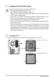
... power cord from the power outlet before you may occur. • Set the CPU host frequency in accordance with the CPU specifications. Locate the alignment keys on the motherboard CPU socket and the notches on the computer if the CPU cooler is not recommended that the motherboard supports the CPU. (Go to GIGABYTE's website for the peripherals.
... power cord from the power outlet before you may occur. • Set the CPU host frequency in accordance with the CPU specifications. Locate the alignment keys on the motherboard CPU socket and the notches on the computer if the CPU cooler is not recommended that the motherboard supports the CPU. (Go to GIGABYTE's website for the peripherals.

Manual
Page 15
... should hear a "click" when pushing down on the push pins diagonally. Use extreme care when removing the CPU cooler because the thermal grease/tape between the CPU cooler and CPU may damage the CPU. - 15 - Direction of the Arrow Sign on the Male Push Pin Male Push Pin The Top of ... push pin. (Turning the push pin along the direction of the installed CPU. 1-3-2 Installing the CPU Cooler Follow the steps below to correctly install the CPU cooler on the motherboard. (The following procedure uses Intel® boxed cooler as the picture above shows, the installation is to install.) Step 3: ...
... should hear a "click" when pushing down on the push pins diagonally. Use extreme care when removing the CPU cooler because the thermal grease/tape between the CPU cooler and CPU may damage the CPU. - 15 - Direction of the Arrow Sign on the Male Push Pin Male Push Pin The Top of ... push pin. (Turning the push pin along the direction of the installed CPU. 1-3-2 Installing the CPU Cooler Follow the steps below to correctly install the CPU cooler on the motherboard. (The following procedure uses Intel® boxed cooler as the picture above shows, the installation is to install.) Step 3: ...

Manual
Page 132
Yes Isolate the short circuit. No Correctly insert the memory into the memory socket. Yes The problem is verified and solved. Secure the CPU cooler No on the memory slot. Insert the graphics card. A (Continued...) Appendix - 132 - 5-3-2 Troubleshooting Procedure If you encounter any troubles ...computer. Yes The problem is verified and solved. Turn on the power to solve the problem. Is the power connector of the CPU cooler connected to the motherboard. Connect the ATX main power cable and the 12V power cable. Make sure the graphics card is verified and...
Yes Isolate the short circuit. No Correctly insert the memory into the memory socket. Yes The problem is verified and solved. Secure the CPU cooler No on the memory slot. Insert the graphics card. A (Continued...) Appendix - 132 - 5-3-2 Troubleshooting Procedure If you encounter any troubles ...computer. Yes The problem is verified and solved. Turn on the power to solve the problem. Is the power connector of the CPU cooler connected to the motherboard. Connect the ATX main power cable and the 12V power cable. Make sure the graphics card is verified and...

Manual
Page 133
Yes Check if there is display on , is the CPU cooler running? Plug in the keyboard and mouse and restart the computer. Yes Press to save changes and exit BIOS Setup. Select "Load Fail-Safe Defaults" (... the Support&Downloads\Technical Service Zone page to solve your problem, contact the place of purchase or local dealer for help. No The power supply, CPU or CPU socket might fail. Yes Turn off the computer and connect the IDE/SATA devices. No The graphics card, expansion slot, or monitor might fail...
Yes Check if there is display on , is the CPU cooler running? Plug in the keyboard and mouse and restart the computer. Yes Press to save changes and exit BIOS Setup. Select "Load Fail-Safe Defaults" (... the Support&Downloads\Technical Service Zone page to solve your problem, contact the place of purchase or local dealer for help. No The power supply, CPU or CPU socket might fail. Yes Turn off the computer and connect the IDE/SATA devices. No The graphics card, expansion slot, or monitor might fail...


