
Manual
Page 1
... SATA controllers. Setting Up a RAID-Ready System Step 1: Configure the system BIOS Enter the system BIOS Setup program, set up all motherboard drivers, including the X.H.D utility. Exits the X.H.D utility: Click Cancel to exit the X.H.D utility. (Note 1) The X.H.D utility only... supports the SATA controllers integrated in the array. ) 1. eXtreme Hard Drive (X.H.D) With GIGABYTE eXtreme Hard Drive (X.H.D)(Note 1), users can quickly configure a RAIDready system for RAID 0 when a new SATA drive is greater than the RAID-ready...
... SATA controllers. Setting Up a RAID-Ready System Step 1: Configure the system BIOS Enter the system BIOS Setup program, set up all motherboard drivers, including the X.H.D utility. Exits the X.H.D utility: Click Cancel to exit the X.H.D utility. (Note 1) The X.H.D utility only... supports the SATA controllers integrated in the array. ) 1. eXtreme Hard Drive (X.H.D) With GIGABYTE eXtreme Hard Drive (X.H.D)(Note 1), users can quickly configure a RAIDready system for RAID 0 when a new SATA drive is greater than the RAID-ready...

Manual
Page 1
GA-X58A-UD7 LGA1366 socket motherboard for Intel® Core™ i7 processor family User's Manual Rev. 1002 12ME-X58AUD7-1002R
GA-X58A-UD7 LGA1366 socket motherboard for Intel® Core™ i7 processor family User's Manual Rev. 1002 12ME-X58AUD7-1002R
Manual
Page 2
Motherboard GA-X58A-UD7 Nov. 13, 2009 Motherboard GA-X58A-UD7 Nov. 13, 2009
Motherboard GA-X58A-UD7 Nov. 13, 2009 Motherboard GA-X58A-UD7 Nov. 13, 2009

Manual
Page 3
...-related information, check on our website at: http://www.gigabyte.com.tw Identifying Your Motherboard Revision The revision number on our website. Documentation Classifications In order to assist in this product, GIGABYTE provides the following types of documentations: For quick set-up... how to the specifications and features in the use GIGABYTE's unique features, read or download the information on/from the Support&Downloads\Motherboard\Technology Guide page on your motherboard revision before updating motherboard BIOS, drivers, or when looking for technical information....
...-related information, check on our website at: http://www.gigabyte.com.tw Identifying Your Motherboard Revision The revision number on our website. Documentation Classifications In order to assist in this product, GIGABYTE provides the following types of documentations: For quick set-up... how to the specifications and features in the use GIGABYTE's unique features, read or download the information on/from the Support&Downloads\Motherboard\Technology Guide page on your motherboard revision before updating motherboard BIOS, drivers, or when looking for technical information....

Manual
Page 4
Table of Contents Box Contents...6 Optional Items...6 GA-X58A-UD7 Motherboard Layout 7 Block Diagram...8 Chapter 1 Hardware Installation 9 1-1 Installation Precautions 9 1-2 Product Specifications 10 1-3 Installing the CPU and CPU Cooler 13 1-3-1 Installing the CPU 13 1-3-2 Installing the CPU ...
Table of Contents Box Contents...6 Optional Items...6 GA-X58A-UD7 Motherboard Layout 7 Block Diagram...8 Chapter 1 Hardware Installation 9 1-1 Installation Precautions 9 1-2 Product Specifications 10 1-3 Installing the CPU and CPU Cooler 13 1-3-1 Installing the CPU 13 1-3-2 Installing the CPU ...

Manual
Page 6
...1394a bracket (Part No. 12CF1-1IE008-0*R) 2-port SATA power cable (Part No. 12CF1-2SERPW-0*R) S/PDIF In cable (Part No. 12CR1-1SPDIN-0*R) - 6 - Box Contents GA-X58A-UD7 motherboard Motherboard driver disk User's Manual Quick Installation Guide One IDE cable Four SATA 3Gb/s cables One SATA bracket I/O Shield One Hybrid Silent-Pipe module kit 2-Way... SLI bridge connector 3-Way SLI bridge connector • The box contents above are subject to change without notice. • The motherboard image is for reference only and the actual items shall depend on the product package you obtain.
...1394a bracket (Part No. 12CF1-1IE008-0*R) 2-port SATA power cable (Part No. 12CF1-2SERPW-0*R) S/PDIF In cable (Part No. 12CR1-1SPDIN-0*R) - 6 - Box Contents GA-X58A-UD7 motherboard Motherboard driver disk User's Manual Quick Installation Guide One IDE cable Four SATA 3Gb/s cables One SATA bracket I/O Shield One Hybrid Silent-Pipe module kit 2-Way... SLI bridge connector 3-Way SLI bridge connector • The box contents above are subject to change without notice. • The motherboard image is for reference only and the actual items shall depend on the product package you obtain.

Manual
Page 7
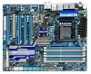
... CMOS_SW USB_1394_ESATA_2 USB_1394_ESATA_1 CPU_FAN CPU Voltage L1/2/3 CPU TEMP L1/2 LGA1366 RST_SW PW_SW GA-X58A-UD7 PWR_FAN USB_LAN ATX USB30_LAN JMicron JMB362 DDR Voltage LED DDR PHASE LED F_AUDIO NB ...GIGABYTE SATA2 Debug LED (Note 2) GSATA2_9 GSATA2_8 SYS_FAN2 F_USB2 IDE F_PANEL FDD F_1394 F_USB1 (Note 1) Due to Chapter 5. - 7 - For a longer expansion card, use other expansion slots. (Note 2) For error code information, please refer to a hardware limitation, the PCIEX1_1 slot can only accommodate a shorter PCI Express x1 expansion card. GA-X58A-UD7 Motherboard...
... CMOS_SW USB_1394_ESATA_2 USB_1394_ESATA_1 CPU_FAN CPU Voltage L1/2/3 CPU TEMP L1/2 LGA1366 RST_SW PW_SW GA-X58A-UD7 PWR_FAN USB_LAN ATX USB30_LAN JMicron JMB362 DDR Voltage LED DDR PHASE LED F_AUDIO NB ...GIGABYTE SATA2 Debug LED (Note 2) GSATA2_9 GSATA2_8 SYS_FAN2 F_USB2 IDE F_PANEL FDD F_1394 F_USB1 (Note 1) Due to Chapter 5. - 7 - For a longer expansion card, use other expansion slots. (Note 2) For error code information, please refer to a hardware limitation, the PCIEX1_1 slot can only accommodate a shorter PCI Express x1 expansion card. GA-X58A-UD7 Motherboard...

Manual
Page 9
...ESD wrist strap, keep your hands dry and first touch a metal object to eliminate static electricity. • Prior to installing the motherboard, please have it on top of an antistatic pad or within the computer casing. • Do not place the computer system on...using the product, please verify that all cables and power connectors of electrostatic discharge (ESD). Chapter 1 Hardware Installation 1-1 Installation Precautions The motherboard contains numerous delicate electronic circuits and components which can lead to damage to system components as well as physical harm to the user. &#...
...ESD wrist strap, keep your hands dry and first touch a metal object to eliminate static electricity. • Prior to installing the motherboard, please have it on top of an antistatic pad or within the computer casing. • Do not place the computer system on...using the product, please verify that all cables and power connectors of electrostatic discharge (ESD). Chapter 1 Hardware Installation 1-1 Installation Precautions The motherboard contains numerous delicate electronic circuits and components which can lead to damage to system components as well as physical harm to the user. &#...

Manual
Page 12
... card, the PCIEX16_1 slot will depend on the CPU/ system cooler you are installing two PCI Express graphics cards, it in EasyTune may differ by motherboard model. when PCIEX8_2 is recommended that you install them in the PCIEX16_1 and PCIEX16_2 slots. (Note 3) The PCIEX8_1 and PCIEX8_2 slots share bandwidth with the...
... card, the PCIEX16_1 slot will depend on the CPU/ system cooler you are installing two PCI Express graphics cards, it in EasyTune may differ by motherboard model. when PCIEX8_2 is recommended that you install them in the PCIEX16_1 and PCIEX16_2 slots. (Note 3) The PCIEX8_1 and PCIEX8_2 slots share bandwidth with the...
Manual
Page 13
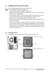
... do so according to your hardware specifications including the CPU, graphics card, memory, hard drive, etc. 1-3-1 Installing the CPU A. Locate the alignment keys on the motherboard CPU socket and the notches on the CPU Notch Notch - 13 - If you may occur. • Set the CPU host frequency in accordance with the... meet the standard requirements for the latest CPU support list.) • Always turn on the computer if the CPU cooler is not recommended that the motherboard supports the CPU. (Go to GIGABYTE's website for the peripherals. Hardware Installation
... do so according to your hardware specifications including the CPU, graphics card, memory, hard drive, etc. 1-3-1 Installing the CPU A. Locate the alignment keys on the motherboard CPU socket and the notches on the CPU Notch Notch - 13 - If you may occur. • Set the CPU host frequency in accordance with the... meet the standard requirements for the latest CPU support list.) • Always turn on the computer if the CPU cooler is not recommended that the motherboard supports the CPU. (Go to GIGABYTE's website for the peripherals. Hardware Installation
Manual
Page 14
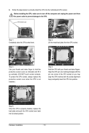
..., always replace the protective socket cover when the CPU is properly inserted, replace the load plate and push the CPU socket lever back into the motherboard CPU socket.
..., always replace the protective socket cover when the CPU is properly inserted, replace the load plate and push the CPU socket lever back into the motherboard CPU socket.

Manual
Page 15
... above shows, the installation is to install.) Step 3: Place the cooler atop the CPU, aligning the four push pins through the pin holes on the motherboard. Step 4: You should hear a "click" when pushing down on installing the cooler.) Step 5: After the installation, check the back of the CPU ...on the surface of arrow is to remove the cooler, on the contrary, is complete. Step 6: Finally, attach the power connector of the motherboard. Push down each push pin. Use extreme care when removing the CPU cooler because the thermal grease/tape between the CPU cooler and CPU may...
... above shows, the installation is to install.) Step 3: Place the cooler atop the CPU, aligning the four push pins through the pin holes on the motherboard. Step 4: You should hear a "click" when pushing down on installing the cooler.) Step 5: After the installation, check the back of the CPU ...on the surface of arrow is to remove the cooler, on the contrary, is complete. Step 6: Finally, attach the power connector of the motherboard. Push down each push pin. Use extreme care when removing the CPU cooler because the thermal grease/tape between the CPU cooler and CPU may...
Manual
Page 16
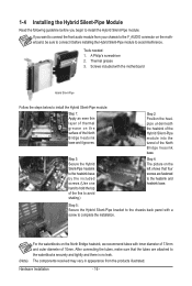
...the included screws.(Use one hand to hold the top of the fins to complete the installation. (Note) For the waterblocks on the motherboard, be sure to connect it grooves. The components received may vary in appearance from your chassis to the F_AUDIO connector on the North ... 7.5mm and outer diameter of the North Bridge heasink base. Step 5: Secure the Hybrid Silent-Pipe bracket to the chassis back panel with the motherboard Hybrid Silent-Pipe Follow the steps below to the waterblocks securely and tightly and there is no leak. A Philip's screwdriver 2. Screws included with ...
...the included screws.(Use one hand to hold the top of the fins to complete the installation. (Note) For the waterblocks on the motherboard, be sure to connect it grooves. The components received may vary in appearance from your chassis to the F_AUDIO connector on the North ... 7.5mm and outer diameter of the North Bridge heasink base. Step 5: Secure the Hybrid Silent-Pipe bracket to the chassis back panel with the motherboard Hybrid Silent-Pipe Follow the steps below to the waterblocks securely and tightly and there is no leak. A Philip's screwdriver 2. Screws included with ...

Manual
Page 17
...message which says mem- Intel?Flex Memory Technology offers greater flexibility to upgrade by allowing different memory sizes to be used. (Go to GIGABYTE's website for the latest memory support list.) • Always turn off the computer and unplug the power cord from the power outlet ...before installing the memory to insert the memory, switch the direction. 1-5-1 Dual/3 Channel Memory Configuration This motherboard provides six DDR3 memory sockets and supports Dual/3 Channel Technology. DS/SS - - - - DS/SS Four Modules DS/SS DS/SS - -...
...message which says mem- Intel?Flex Memory Technology offers greater flexibility to upgrade by allowing different memory sizes to be used. (Go to GIGABYTE's website for the latest memory support list.) • Always turn off the computer and unplug the power cord from the power outlet ...before installing the memory to insert the memory, switch the direction. 1-5-1 Dual/3 Channel Memory Configuration This motherboard provides six DDR3 memory sockets and supports Dual/3 Channel Technology. DS/SS - - - - DS/SS Four Modules DS/SS DS/SS - -...

Manual
Page 18
... damage to correctly install your fingers on the memory and insert it can only fit in the memory sockets. Place the memory module on this motherboard. As indicated in the picture on the left, place your memory modules in one direction. Step 1: Note the orientation of the memory, push down on...
... damage to correctly install your fingers on the memory and insert it can only fit in the memory sockets. Place the memory module on this motherboard. As indicated in the picture on the left, place your memory modules in one direction. Step 1: Note the orientation of the memory, push down on...

Manual
Page 19
... then pull the card straight up from the slot. - 19 - If necessary, go to BIOS Setup to install an expansion card: • Make sure the motherboard supports the expansion card. Secure the card's metal bracket to the chassis back panel with the expansion card in the slot. 3. Install the driver provided...
... then pull the card straight up from the slot. - 19 - If necessary, go to BIOS Setup to install an expansion card: • Make sure the motherboard supports the expansion card. Secure the card's metal bracket to the chassis back panel with the expansion card in the slot. 3. Install the driver provided...

Manual
Page 20
... Enable CrossFireX Function For 2-Way CrossFireX: After installing the graphics card driver in the operating system, go to the NVIDIA Control Panel. A CrossFireX/SLI-supported motherboard with your graphics cards for the power requirement) B. Click OK to the CrossFireX menu and select the Enable CrossFireX™ check box. Step 3: Plug the...
... Enable CrossFireX Function For 2-Way CrossFireX: After installing the graphics card driver in the operating system, go to the NVIDIA Control Panel. A CrossFireX/SLI-supported motherboard with your graphics cards for the power requirement) B. Click OK to the CrossFireX menu and select the Enable CrossFireX™ check box. Step 3: Plug the...
Manual
Page 21
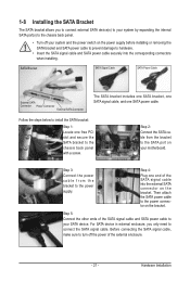
... the internal SATA port(s) to the chassis back panel. • Turn off the power of the SATA signal cable and SATA power cable to your motherboard. Before connecting the SATA signal cable, make sure to turn off your system and the power switch on your SATA device. SATA Bracket SATA Signal...
... the internal SATA port(s) to the chassis back panel. • Turn off the power of the SATA signal cable and SATA power cable to your motherboard. Before connecting the SATA signal cable, make sure to turn off your system and the power switch on your SATA device. SATA Bracket SATA Signal...
Manual
Page 22
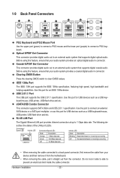
... is occurring LAN Port Off 10 Mbps data rate • When removing the cable connected to a back panel connector, first remove the cable from the motherboard. • When removing the cable, pull it side to side to an external audio system that supports digital optical audio. Use this port for USB...
... is occurring LAN Port Off 10 Mbps data rate • When removing the cable connected to a back panel connector, first remove the cable from the motherboard. • When removing the cable, pull it side to side to an external audio system that supports digital optical audio. Use this port for USB...

Manual
Page 24
... Temperature Indicator LEDs The two sets of temperature indicator LEDs indicate the temperature level of lighted LEDs. 1-10 Onboard LEDs and Switches Overvoltage LEDs This motherboard contains 4 sets of overvoltage LEDs which level the CPU is below 60oC;
... Temperature Indicator LEDs The two sets of temperature indicator LEDs indicate the temperature level of lighted LEDs. 1-10 Onboard LEDs and Switches Overvoltage LEDs This motherboard contains 4 sets of overvoltage LEDs which level the CPU is below 60oC;


