FTOS Command Reference Guide
Page 61
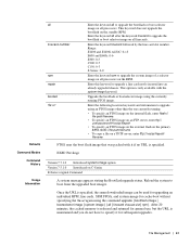
... is maintained and you do not have to upgrade the system image of a selector image on all | linecard linecard-slot | rpm}. Range: E1200 and E1200i AC/DC: 0-13 E600 and E600i: 0-6 E300: 0-5 C300: 0-7 C150: 0-3 S-Series: 0-0 Enter the keyword rpm to specify it if no URL is specified, the same downloaded image...
... is maintained and you do not have to upgrade the system image of a selector image on all | linecard linecard-slot | rpm}. Range: E1200 and E1200i AC/DC: 0-13 E600 and E600i: 0-6 E300: 0-5 C300: 0-7 C150: 0-3 S-Series: 0-0 Enter the keyword rpm to specify it if no URL is specified, the same downloaded image...

FTOS Command Reference Guide
Page 108
...output differ from the C-Series/E-Series version. Fan Status Unit TrayStatus Fan0 Fan1 Fan2 Fan3 Fan4 Fan5 0 up up up up up up up AC 0 1 absent -- Enter the keyword stack-unit followed by the unit-id to view all -- Command Modes EXEC EXEC Privilege Command History ... Monitoring Enter the keyword pem to view information on power entry modules. Enter the keyword fan to view only information on the fans. www.dell.com | support.dell.com FanNumber 0 1 2 3 4 5 FTOS# Speed 4170 4140 3870 4140 3870 3810 Status up up up up up up show environment (S-Series)...
...output differ from the C-Series/E-Series version. Fan Status Unit TrayStatus Fan0 Fan1 Fan2 Fan3 Fan4 Fan5 0 up up up up up up up AC 0 1 absent -- Enter the keyword stack-unit followed by the unit-id to view all -- Command Modes EXEC EXEC Privilege Command History ... Monitoring Enter the keyword pem to view information on power entry modules. Enter the keyword fan to view only information on the fans. www.dell.com | support.dell.com FanNumber 0 1 2 3 4 5 FTOS# Speed 4170 4140 3870 4140 3870 3810 Status up up up up up up show environment (S-Series)...

FTOS Command Reference Guide
Page 109
... and expanded to include SFP+ media in C-Series. Fan Status Unit TrayStatus Fan0 Fan1 Fan2 Fan3 Fan4 Fan5 0 up up up up up up up AC 0 1 absent FTOS#show environment fan -- Power Supplies -- Syntax show inventory (C-Series and E-Series) c e Display the chassis type, components (including media), FTOS version including hardware identification...
... and expanded to include SFP+ media in C-Series. Fan Status Unit TrayStatus Fan0 Fan1 Fan2 Fan3 Fan4 Fan5 0 up up up up up up up AC 0 1 absent FTOS#show environment fan -- Power Supplies -- Syntax show inventory (C-Series and E-Series) c e Display the chassis type, components (including media), FTOS version including hardware identification...
FTOS Command Reference Guide
Page 110
... Number Revision C300 TY000001400 7520029999 04 3 LC-CB-GE-48T FX000020075 7520036700 01 0 LC-CB-RPM 0060361 7520029300 02 0 CC-C-1200W-AC N/A N/A N/A 1 CC-C-1200W-AC N/A N/A N/A 0 CC-C300-FAN * - www.dell.com | support.dell.com Usage Information Example (C300) Version 6.2.1.0 Version 5.3.1.0 Expanded to include Software Protocol Configured field on E-Series Introduced on E-Series The show...
... Number Revision C300 TY000001400 7520029999 04 3 LC-CB-GE-48T FX000020075 7520036700 01 0 LC-CB-RPM 0060361 7520029300 02 0 CC-C-1200W-AC N/A N/A N/A 1 CC-C-1200W-AC N/A N/A N/A 0 CC-C300-FAN * - www.dell.com | support.dell.com Usage Information Example (C300) Version 6.2.1.0 Version 5.3.1.0 Expanded to include Software Protocol Configured field on E-Series Introduced on E-Series The show...

FTOS Command Reference Guide
Page 112
... values Command Modes CONFIGURATION Command History Usage Version 7.6.1.0 Introduced this version of the stack member for S-Series. www.dell.com | support.dell.com Parameters media slot (OPTIONAL) Enter the keyword media followed by the stack ID of the command for which you...E8-3-12-2 Unit Type Serial Number Part Number Rev Piece Part ID * 2 S4810-01-64F HADL123J20113 7590009602 A N/A 2 S4810-PWR-AC H6DL123J20113 7590008502 A N/A 2 S4810-FAN N/A N/A N/A N/A 2 S4810-FAN N/A N/A N/A N/A Rev Svc Tag Exprs Svc Code N/A N/A N/A N/A N/A N/A N/A N/A N/A N/A N/A N/A * -
... values Command Modes CONFIGURATION Command History Usage Version 7.6.1.0 Introduced this version of the stack member for S-Series. www.dell.com | support.dell.com Parameters media slot (OPTIONAL) Enter the keyword media followed by the stack ID of the command for which you...E8-3-12-2 Unit Type Serial Number Part Number Rev Piece Part ID * 2 S4810-01-64F HADL123J20113 7590009602 A N/A 2 S4810-PWR-AC H6DL123J20113 7590008502 A N/A 2 S4810-FAN N/A N/A N/A N/A 2 S4810-FAN N/A N/A N/A N/A Rev Svc Tag Exprs Svc Code N/A N/A N/A N/A N/A N/A N/A N/A N/A N/A N/A N/A * -

FTOS Command Reference Guide
Page 115
...; C. The [Booted] keyword next to the version states which specifies the manufacturing vendor. Displays an internal code, which version was used in the chassis: • AC = AC power supply • DC = DC Power Entry Module (PEM) Displays OK if the line voltage is operating in the line card. Table 4-1. Descriptions for the...
...; C. The [Booted] keyword next to the version states which specifies the manufacturing vendor. Displays an internal code, which version was used in the chassis: • AC = AC power supply • DC = DC Power Entry Module (PEM) Displays OK if the line voltage is operating in the line card. Table 4-1. Descriptions for the...

FTOS Command Reference Guide
Page 139
... : yes POE Capable : no FIPS Mode : disabled Burned In MAC : 00:01:e8:8b:3e:42 No Of MACs : 3 -- Unit Bay Status Type FanStatus 0 0 up AC up 0 1 absent absent -- Power Supplies -- FTOS#show system brief command. Fan Status -Unit Bay TrayStatus Fan0 Speed Fan1 Speed Control and Monitoring | 139 Unit Type...
... : yes POE Capable : no FIPS Mode : disabled Burned In MAC : 00:01:e8:8b:3e:42 No Of MACs : 3 -- Unit Bay Status Type FanStatus 0 0 up AC up 0 1 absent absent -- Power Supplies -- FTOS#show system brief command. Fan Status -Unit Bay TrayStatus Fan0 Speed Fan1 Speed Control and Monitoring | 139 Unit Type...

FTOS Command Reference Guide
Page 140
...S50-01-24G-2S 1 2 0 online S50-01-10GE-2P 2 2 1 online S50-01-24G-2S 1 -- Fan Status -- Unit Bay Status Type 1 0 up AC 1 1 absent 2 0 up 0 1 absent absent -- Unit UnitType Status ReqTyp CurTyp Version Ports 0 Member not present 1 Standby online S50V S50V 7.7.1.0 52 2 Mgmt ... 0 0 up 0 1 up up 6720 up 6960 up 6720 up FTOS# 140 | Control and Monitoring Power Supplies -- www.dell.com | support.dell.com Example (show system brief Stack MAC : 0:1:e8:d6:4:70 -- Fan Status -- Unit TrayStatus Fan0 Fan1 Fan2 Fan3 Fan4 Fan5...
...S50-01-24G-2S 1 2 0 online S50-01-10GE-2P 2 2 1 online S50-01-24G-2S 1 -- Fan Status -- Unit Bay Status Type 1 0 up AC 1 1 absent 2 0 up 0 1 absent absent -- Unit UnitType Status ReqTyp CurTyp Version Ports 0 Member not present 1 Standby online S50V S50V 7.7.1.0 52 2 Mgmt ... 0 0 up 0 1 up up 6720 up 6960 up 6720 up FTOS# 140 | Control and Monitoring Power Supplies -- www.dell.com | support.dell.com Example (show system brief Stack MAC : 0:1:e8:d6:4:70 -- Fan Status -- Unit TrayStatus Fan0 Fan1 Fan2 Fan3 Fan4 Fan5...

FTOS Command Reference Guide
Page 141
... - 2-port 10GE XFP (SB) -- Power Supplies -- Module 1 - Fan Status Unit TrayStatus Fan0 Fan1 Fan2 Fan3 Fan4 Fan5 0 up FTOS# up up up up up up AC 0 1 absent -- Status : online Module Type : S50-01-10GE-2C Num Ports : 2 Hot Pluggable : no - 2-port 10GE CX4 (SB) - Control and Monitoring | 141 Display information about...
... - 2-port 10GE XFP (SB) -- Power Supplies -- Module 1 - Fan Status Unit TrayStatus Fan0 Fan1 Fan2 Fan3 Fan4 Fan5 0 up FTOS# up up up up up up AC 0 1 absent -- Status : online Module Type : S50-01-10GE-2C Num Ports : 2 Hot Pluggable : no - 2-port 10GE CX4 (SB) - Control and Monitoring | 141 Display information about...

Getting Started Guide
Page 3
Contents 1 About this Guide 1 2 Introduction 3 Product Description 3 3 Hardware Overview 5 Fans 6 Front Panel 7 System Status 8 4 Installation 11 Unpacking the Switch 11 Package Contents 11 Unpacking Steps 11 Power Supplies 12 Install an AC or DC Power Supply 13 Rack Mounting the Switch 14 Rack Mounting Safety Considerations 14 Installing the Dell ReadyRails System 15 Installing the Switch 19 5 Technical Specifications 21 Chassis Physical Design 21 Environmental Parameters 21 Power Requirements 22 DC Input Specification 22 Contents 1
Contents 1 About this Guide 1 2 Introduction 3 Product Description 3 3 Hardware Overview 5 Fans 6 Front Panel 7 System Status 8 4 Installation 11 Unpacking the Switch 11 Package Contents 11 Unpacking Steps 11 Power Supplies 12 Install an AC or DC Power Supply 13 Rack Mounting the Switch 14 Rack Mounting Safety Considerations 14 Installing the Dell ReadyRails System 15 Installing the Switch 19 5 Technical Specifications 21 Chassis Physical Design 21 Environmental Parameters 21 Power Requirements 22 DC Input Specification 22 Contents 1

Getting Started Guide
Page 12
... (SKUs) that support the following configurations. S4820T Fan Modules Fan Module 0 Fan Module 1 Grab Handles 6 Hardware Overview Figure 1-1. The power supply units (PSUs) are to be installed at the customer site (refer to Power Supplies). • AC PSU with fan airflow from I/O to PSU • AC PSU with fan airflow from PSU to...
... (SKUs) that support the following configurations. S4820T Fan Modules Fan Module 0 Fan Module 1 Grab Handles 6 Hardware Overview Figure 1-1. The power supply units (PSUs) are to be installed at the customer site (refer to Power Supplies). • AC PSU with fan airflow from I/O to PSU • AC PSU with fan airflow from PSU to...

Getting Started Guide
Page 17
... When unpacking each switch, make sure that the following items are included: • One S4820T switch • One RJ-45 to DB-9 female cable • Two sets of rail kits (no tools required) • One PSU • One AC power cord (country/region specific) • Getting Started Guide • Safety and Regulatory...
... When unpacking each switch, make sure that the following items are included: • One S4820T switch • One RJ-45 to DB-9 female cable • Two sets of rail kits (no tools required) • One PSU • One AC power cord (country/region specific) • Getting Started Guide • Safety and Regulatory...

Getting Started Guide
Page 18
Dell Force10 recommends using power supply 1 (PSU1) as the blank plate slot. WARNING: Electrostatic discharge (ESD) damage can remove and replace one PSU while the other PSU slot. You cannot replace an AC PSU with a DC PSU and you do not ground your local electrical requirements. The PSUs are mishandled. S4820T...use a single PSU, you can occur if components are field replaceable. If you cannot replace an AC-R PSU with a DC-R PSU. Figure 1-4. The S4820T supports AC and DC power supplies with two air-flow directions (I /O). Two PSUs are required for the system....
Dell Force10 recommends using power supply 1 (PSU1) as the blank plate slot. WARNING: Electrostatic discharge (ESD) damage can remove and replace one PSU while the other PSU slot. You cannot replace an AC PSU with a DC PSU and you do not ground your local electrical requirements. The PSUs are mishandled. S4820T...use a single PSU, you can occur if components are field replaceable. If you cannot replace an AC-R PSU with a DC-R PSU. Figure 1-4. The S4820T supports AC and DC power supplies with two air-flow directions (I /O). Two PSUs are required for the system....

Getting Started Guide
Page 19
... 1 (PSU1) as the blank plate slot. Installation 13 When the PSU is correctly installed, the power connector is on the S4820T switch. Install an AC or DC Power Supply To install an AC or DC power supply, follow these steps: NOTE: The PSU slides into a slot as this may be selected. 2 Remove... cord (AC 3 prong or DC wiring) from the switch PSU to the external power source (either of the two PSU slots may damage the PSU or the S4820T chassis. NOTE: The system powers up as soon as the cables are connected between the power supply and the power source. Dell Force10 recommends using...
... 1 (PSU1) as the blank plate slot. Installation 13 When the PSU is correctly installed, the power connector is on the S4820T switch. Install an AC or DC Power Supply To install an AC or DC power supply, follow these steps: NOTE: The PSU slides into a slot as this may be selected. 2 Remove... cord (AC 3 prong or DC wiring) from the switch PSU to the external power source (either of the two PSU slots may damage the PSU or the S4820T chassis. NOTE: The system powers up as soon as the cables are connected between the power supply and the power source. Dell Force10 recommends using...

Installing the S4820T System
Page 3
... 11 Determining System Status 11 LED Displays 11 Basic Installation Requirements 14 Orderable S4820T Components 15 3 Site Location and Preparation Site Selection 18 Cabinet Placement 18 Rack...18 Fan Combinations 19 Power 19 Storing Components 19 4 Installing the S4820T Unpacking the S4820T Switch 21 Package Contents 21 Unpacking Steps 22 Installing Rack or Cabinet Hardware 23... 23 Installing the Dell ReadyRails System 24 Two-post Flush-mount Configuration 25 Two-post Center-mount Configuration 26 Four-post Threaded Configuration 27 Installing the S4820T Switch 28 1U ...
... 11 Determining System Status 11 LED Displays 11 Basic Installation Requirements 14 Orderable S4820T Components 15 3 Site Location and Preparation Site Selection 18 Cabinet Placement 18 Rack...18 Fan Combinations 19 Power 19 Storing Components 19 4 Installing the S4820T Unpacking the S4820T Switch 21 Package Contents 21 Unpacking Steps 22 Installing Rack or Cabinet Hardware 23... 23 Installing the Dell ReadyRails System 24 Two-post Flush-mount Configuration 25 Two-post Center-mount Configuration 26 Four-post Threaded Configuration 27 Installing the S4820T Switch 28 1U ...

Installing the S4820T System
Page 4
...dell.com | support.dell.com 4| Removing QSFP+ Optics 31 Splitting QSFP+ Ports to SFP+ or RJ-45 Ports 31 Important Points to Know 31 Powering Up the S4820T Switch 32 Power Up Sequence 32 Connecting the Stacking Ports (Optional 33 Important Port-Stacking Points to Know 33 Connect Two S4820T Systems 34 Connect Three S4820T... Systems 35 Hot-Swapping Units in a Stack 36 5 Power Supplies Components 39 Installing an AC or DC Power Supply 40 Replacing an AC or DC Power Supply 40 Connecting a DC Power...
...dell.com | support.dell.com 4| Removing QSFP+ Optics 31 Splitting QSFP+ Ports to SFP+ or RJ-45 Ports 31 Important Points to Know 31 Powering Up the S4820T Switch 32 Power Up Sequence 32 Connecting the Stacking Ports (Optional 33 Important Port-Stacking Points to Know 33 Connect Two S4820T Systems 34 Connect Three S4820T... Systems 35 Hot-Swapping Units in a Stack 36 5 Power Supplies Components 39 Installing an AC or DC Power Supply 40 Replacing an AC or DC Power Supply 40 Connecting a DC Power...

Installing the S4820T System
Page 14
...dell.com | support.dell.com Basic Installation Requirements Detailed installation instructions for the S4820T are provided in Chapter 3, Site Location and Preparation and Chapter 4, Installing the S4820T, however, the following, is an initial list of components required for a successful installation of the S4820T: • S4820T chassis (or multiple chassis, if stacking) • If you ordered AC... units, cables to connect the AC power source to each of the chassis' AC power supplies (...
...dell.com | support.dell.com Basic Installation Requirements Detailed installation instructions for the S4820T are provided in Chapter 3, Site Location and Preparation and Chapter 4, Installing the S4820T, however, the following, is an initial list of components required for a successful installation of the S4820T: • S4820T chassis (or multiple chassis, if stacking) • If you ordered AC... units, cables to connect the AC power source to each of the chassis' AC power supplies (...

Installing the S4820T System
Page 15
... supply and 2 fan subsystems (airflow from I/O side to power supply side) S4820T AC Reverse Airflow: 48 port 10G RJ-45 ports with 4 QSFP+ 40G ports, 1 AC power supply and 2 fan subsystems (airflow from power supply side to I/O side) S4820T AC Normal Airflow: 48 port 10G RJ-45 ports with 4 QSFP+ 40G ports, 1... DC power supply and 2 fan subsystems (airflow from I/O side to power supply side) S4820T AC Reverse Airflow: 48 port 10G RJ-45 ports with 4 QSFP+ 40G ports, 1 DC power supply and 2 fan subsystems (airflow from power supply side to I/O...
... supply and 2 fan subsystems (airflow from I/O side to power supply side) S4820T AC Reverse Airflow: 48 port 10G RJ-45 ports with 4 QSFP+ 40G ports, 1 AC power supply and 2 fan subsystems (airflow from power supply side to I/O side) S4820T AC Normal Airflow: 48 port 10G RJ-45 ports with 4 QSFP+ 40G ports, 1... DC power supply and 2 fan subsystems (airflow from I/O side to power supply side) S4820T AC Reverse Airflow: 48 port 10G RJ-45 ports with 4 QSFP+ 40G ports, 1 DC power supply and 2 fan subsystems (airflow from power supply side to I/O...

Installing the S4820T System
Page 19
Installation of the fans is done as part of the factory install based on the AC system. The S4820T never intentionally turns off the fans. The system is connected between the system and the power source. CAUTION: Use the power supply cord as the ... of clearance around the exhaust vents. Power Use the appropriate power cord with the S4820T system to connect the chassis to see the log messages. Storing Components If you do not install your S4820T and components immediately, Dell Force10 recommends properly storing the system and all optional components until you service the power supply...
Installation of the fans is done as part of the factory install based on the AC system. The S4820T never intentionally turns off the fans. The system is connected between the system and the power source. CAUTION: Use the power supply cord as the ... of clearance around the exhaust vents. Power Use the appropriate power cord with the S4820T system to connect the chassis to see the log messages. Storing Components If you do not install your S4820T and components immediately, Dell Force10 recommends properly storing the system and all optional components until you service the power supply...

Installing the S4820T System
Page 21
...the S4820T To install the S4820T system, Dell Force10 recommends completing the installation procedures in the order presented in this system. As with care. Package Contents When unpacking each S4820T switch, make sure that the following items are mishandled. Always handle the S4820T and... Four-post Threaded Configuration 3 Installing the S4820T Switch a 1U Front-rack Installation b Attaching the Ground Cable c Installing an AC or DC Power Supply 4 Installing QSFP+ Optics 5 Connecting the Stacking Ports (Optional) 6 Powering Up the S4820T Switch WARNING: Electrostatic discharge (ESD) damage...
...the S4820T To install the S4820T system, Dell Force10 recommends completing the installation procedures in the order presented in this system. As with care. Package Contents When unpacking each S4820T switch, make sure that the following items are mishandled. Always handle the S4820T and... Four-post Threaded Configuration 3 Installing the S4820T Switch a 1U Front-rack Installation b Attaching the Ground Cable c Installing an AC or DC Power Supply 4 Installing QSFP+ Optics 5 Connecting the Stacking Ports (Optional) 6 Powering Up the S4820T Switch WARNING: Electrostatic discharge (ESD) damage...


