
FTOS Command Reference Guide
Page 108
www.dell.com | support.dell.com FanNumber 0 1 2 3 4 5 FTOS# Speed 4170 4140 3870 4140 3870 3810 Status up up up up up up show environment fan command as up or down. Enter the keyword pem to view information on the fans. Introduced for example, temperature, voltage). Power Supplies --...example shows the output of just showing the fan status as it appears prior to FTOS 7.8.1.0. Range: 0 to display information on power entry modules. Example (show environment all) FTOS#show environment fan command for S-Series is chassis dependent. Fan Status Unit TrayStatus ...
www.dell.com | support.dell.com FanNumber 0 1 2 3 4 5 FTOS# Speed 4170 4140 3870 4140 3870 3810 Status up up up up up up show environment fan command as up or down. Enter the keyword pem to view information on the fans. Introduced for example, temperature, voltage). Power Supplies --...example shows the output of just showing the fan status as it appears prior to FTOS 7.8.1.0. Range: 0 to display information on power entry modules. Example (show environment all) FTOS#show environment fan command for S-Series is chassis dependent. Fan Status Unit TrayStatus ...

FTOS Command Reference Guide
Page 109
... inventory media. Vendor field removed from output of show inventory [media slot] Parameters media slot (OPTIONAL) Enter the keyword media followed by the slot number. Power Supplies -- C-Series Range: 0-7 E-Series Range: 0 to 13 on a E1200, 0 to 6 on a E600/E600i, and 0 to 5 on a E300 Defaults No default behavior or values Command Modes CONFIGURATION...
... inventory media. Vendor field removed from output of show inventory [media slot] Parameters media slot (OPTIONAL) Enter the keyword media followed by the slot number. Power Supplies -- C-Series Range: 0-7 E-Series Range: 0 to 13 on a E1200, 0 to 6 on a E600/E600i, and 0 to 5 on a E300 Defaults No default behavior or values Command Modes CONFIGURATION...

FTOS Command Reference Guide
Page 115
...° C. Displays the two possible Bootflash versions. Minor alarm status if temperature is operating in the chassis: • AC = AC power supply • DC = DC Power Entry Module (PEM) Displays OK if the line voltage is online. Displays the line card serial number. Displays an internal code, which ... linecard show chassis show rpm show linecard output Field Num Ports Up Time FTOS Version Jumbo Capable Boot Flash Ver Memory Size Temperature Power Status Voltage Serial Number Part Num Vendor ID Date Code Description Displays the number of ports in a currently empty slot of the system...
...° C. Displays the two possible Bootflash versions. Minor alarm status if temperature is operating in the chassis: • AC = AC power supply • DC = DC Power Entry Module (PEM) Displays OK if the line voltage is online. Displays the line card serial number. Displays an internal code, which ... linecard show chassis show rpm show linecard output Field Num Ports Up Time FTOS Version Jumbo Capable Boot Flash Ver Memory Size Temperature Power Status Voltage Serial Number Part Num Vendor ID Date Code Description Displays the number of ports in a currently empty slot of the system...
FTOS Command Reference Guide
Page 135
... command) • "reset by master" (peer RPM reset by master RPM) • "over temperature shutdown" • "power supply failed" E-Series possible values: • "normal power-cycle" (insufficient power, normal power cycle) • "reset by user" (automatic failover, software reload of the Control Processor. Displays the memory of both RPMs, or master RPM resetting peer) •...
... command) • "reset by master" (peer RPM reset by master RPM) • "over temperature shutdown" • "power supply failed" E-Series possible values: • "normal power-cycle" (insufficient power, normal power cycle) • "reset by user" (automatic failover, software reload of the Control Processor. Displays the memory of both RPMs, or master RPM resetting peer) •...

FTOS Command Reference Guide
Page 139
... FTOS Version : 4810-8-3-7-1667 Jumbo Capable : yes POE Capable : no FIPS Mode : disabled Burned In MAC : 00:01:e8:8b:3e:42 No Of MACs : 3 -- Power Supplies -- FTOS#show system stack-unit command. Introduced for boot code 2.8.1.1 and newer, while older boot codes are displayed as "Present" Modified output: Added Master Priority...
... FTOS Version : 4810-8-3-7-1667 Jumbo Capable : yes POE Capable : no FIPS Mode : disabled Burned In MAC : 00:01:e8:8b:3e:42 No Of MACs : 3 -- Power Supplies -- FTOS#show system stack-unit command. Introduced for boot code 2.8.1.1 and newer, while older boot codes are displayed as "Present" Modified output: Added Master Priority...

FTOS Command Reference Guide
Page 140
Power Supplies -- Power Supplies -- Fan Status -- Module Info -- Unit Bay TrayStatus Fan0 Speed Fan1 Speed 0 0 up up 6720 up 6960 0 1 up up 6720 up 6960 Speed in RPM Burned ... up up 2 up up up up up up up AC 2 1 absent -- Fan Status -- Unit Bay Status Type FanStatus 0 0 up AC up 0 1 absent absent -- www.dell.com | support.dell.com Example (show system brief) 0 0 up 0 1 up up 6720 up 6960 up 6720 up 6960 Speed in RPM FTOS # FTOS#show system brief Stack...
Power Supplies -- Power Supplies -- Fan Status -- Module Info -- Unit Bay TrayStatus Fan0 Speed Fan1 Speed 0 0 up up 6720 up 6960 0 1 up up 6720 up 6960 Speed in RPM Burned ... up up 2 up up up up up up up AC 2 1 absent -- Fan Status -- Unit Bay Status Type FanStatus 0 0 up AC up 0 1 absent absent -- www.dell.com | support.dell.com Example (show system brief) 0 0 up 0 1 up up 6720 up 6960 up 6720 up 6960 Speed in RPM FTOS # FTOS#show system brief Stack...

FTOS Command Reference Guide
Page 141
... information about the stack ports on running processes. Module 1 - Example (show system stack-unit) Related Commands FTOS#show system stack-ports Display the FTOS version. Power Supplies -- Status : online Module Type : S50-01-10GE-2C Num Ports : 2 Hot Pluggable : no - 2-port 10GE CX4 (SB) -
... information about the stack ports on running processes. Module 1 - Example (show system stack-unit) Related Commands FTOS#show system stack-ports Display the FTOS version. Power Supplies -- Status : online Module Type : S50-01-10GE-2C Num Ports : 2 Hot Pluggable : no - 2-port 10GE CX4 (SB) -

FTOS Command Reference Guide
Page 1575
... alarm: problem with power entry module %s CHM_PWRSRC_CLR ENVMON SUPPLY %CHMGR-5-PEM_OK: Major alarm cleared: power entry module %s is good CHM_MAJ_ALARM_PS ENVMON SUPPLY %CHMGR-0-MAJOR_PS: Major alarm: insufficient power %s CHM_MAJ_ALARM_PS_CLR ENVMON SUPPLY %CHMGR-5-MAJOR_PS_CLR: major alarm cleared: sufficient power CHM_MIN_ALARM_PS ENVMON SUPPLY %CHMGR-1-MINOR_PS: Minor alarm: power supply non-redundant CHM_MIN_ALARM_PS_CLR ENVMON SUPPLY %CHMGR-5-MINOR_PS_CLR: Minor alarm cleared: power supply redundant CHM_MIN_ALRM_TEMP ENVMON TEMP...
... alarm: problem with power entry module %s CHM_PWRSRC_CLR ENVMON SUPPLY %CHMGR-5-PEM_OK: Major alarm cleared: power entry module %s is good CHM_MAJ_ALARM_PS ENVMON SUPPLY %CHMGR-0-MAJOR_PS: Major alarm: insufficient power %s CHM_MAJ_ALARM_PS_CLR ENVMON SUPPLY %CHMGR-5-MAJOR_PS_CLR: major alarm cleared: sufficient power CHM_MIN_ALARM_PS ENVMON SUPPLY %CHMGR-1-MINOR_PS: Minor alarm: power supply non-redundant CHM_MIN_ALARM_PS_CLR ENVMON SUPPLY %CHMGR-5-MINOR_PS_CLR: Minor alarm cleared: power supply redundant CHM_MIN_ALRM_TEMP ENVMON TEMP...

Getting Started Guide
Page 3
Contents 1 About this Guide 1 2 Introduction 3 Product Description 3 3 Hardware Overview 5 Fans 6 Front Panel 7 System Status 8 4 Installation 11 Unpacking the Switch 11 Package Contents 11 Unpacking Steps 11 Power Supplies 12 Install an AC or DC Power Supply 13 Rack Mounting the Switch 14 Rack Mounting Safety Considerations 14 Installing the Dell ReadyRails System 15 Installing the Switch 19 5 Technical Specifications 21 Chassis Physical Design 21 Environmental Parameters 21 Power Requirements 22 DC Input Specification 22 Contents 1
Contents 1 About this Guide 1 2 Introduction 3 Product Description 3 3 Hardware Overview 5 Fans 6 Front Panel 7 System Status 8 4 Installation 11 Unpacking the Switch 11 Package Contents 11 Unpacking Steps 11 Power Supplies 12 Install an AC or DC Power Supply 13 Rack Mounting the Switch 14 Rack Mounting Safety Considerations 14 Installing the Dell ReadyRails System 15 Installing the Switch 19 5 Technical Specifications 21 Chassis Physical Design 21 Environmental Parameters 21 Power Requirements 22 DC Input Specification 22 Contents 1

Getting Started Guide
Page 11
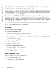
...) • Software-readable thermal monitor • Real time clock (RTC) support • Hot-plugging redundant power supply • Current monitoring for Power management • Removable fan that you can manage • Standard 1U chassis high Hardware Overview 5 The S4820T has the following features: • Supports one RS-232 interface RJ-45 YOST console port...
...) • Software-readable thermal monitor • Real time clock (RTC) support • Hot-plugging redundant power supply • Current monitoring for Power management • Removable fan that you can manage • Standard 1U chassis high Hardware Overview 5 The S4820T has the following features: • Supports one RS-232 interface RJ-45 YOST console port...

Getting Started Guide
Page 12
...) that support the following configurations. Figure 1-1. S4820T Fan Modules Fan Module 0 Fan Module 1 Grab Handles 6 Hardware Overview Installation of the fans is designed to I/O All fans and PSUs in a configuration must be in the same airflow direction. The power supply units (PSUs) are to be installed at the... customer site (refer to Power Supplies). • AC PSU with fan airflow from I/O to PSU • AC PSU with fan airflow from ...
...) that support the following configurations. Figure 1-1. S4820T Fan Modules Fan Module 0 Fan Module 1 Grab Handles 6 Hardware Overview Installation of the fans is designed to I/O All fans and PSUs in a configuration must be in the same airflow direction. The power supply units (PSUs) are to be installed at the... customer site (refer to Power Supplies). • AC PSU with fan airflow from I/O to PSU • AC PSU with fan airflow from ...

Getting Started Guide
Page 15
...side • Blinking blue -Booting • Solid red -Critical system error • Blinking red -Noncritical system error (fan fail, power supply fail) • Off: Normal temperature PSU side • Solid red -Overtemp (Refer NOTE:) • Off -Normal operating PSU... side • Solid green -System Booting or Diagnostics • Solid green -fan powered PSU side and running at the expected rpm • Solid red -fan failed • Solid blue -Switch in stacking...; Off - Hardware Overview 9 Table 1 lists the LED definitions for the S4820T system.
...side • Blinking blue -Booting • Solid red -Critical system error • Blinking red -Noncritical system error (fan fail, power supply fail) • Off: Normal temperature PSU side • Solid red -Overtemp (Refer NOTE:) • Off -Normal operating PSU... side • Solid green -System Booting or Diagnostics • Solid green -fan powered PSU side and running at the expected rpm • Solid red -fan failed • Solid blue -Switch in stacking...; Off - Hardware Overview 9 Table 1 lists the LED definitions for the S4820T system.

Getting Started Guide
Page 18
... two air-flow directions (I/O to PSU and PSU to ensure the power cables meet your equipment correctly, excessive emissions may result. Figure 1-4. Dell Force10 recommends using power supply 1 (PSU1) as the blank plate slot. If you do not ground your local electrical requirements. S4820T Power Supply PS0 PS1 12 Installation Two PSUs are field replaceable. Always wear an...
... two air-flow directions (I/O to PSU and PSU to ensure the power cables meet your equipment correctly, excessive emissions may result. Figure 1-4. Dell Force10 recommends using power supply 1 (PSU1) as the blank plate slot. If you do not ground your local electrical requirements. S4820T Power Supply PS0 PS1 12 Installation Two PSUs are field replaceable. Always wear an...

Getting Started Guide
Page 19
... a redundant PSU (2nd PSU), repeat steps 1 through 5 above using power supply 1 (PSU1) as the cables are connected between the power supply and the power source. Installation 13 Dell Force10 recommends using the 2nd PSU slot on the S4820T switch. Step Task 1 Remove the PSU slot cover from the S4820T (PSU side of switch), either of the two PSU slots...
... a redundant PSU (2nd PSU), repeat steps 1 through 5 above using power supply 1 (PSU1) as the cables are connected between the power supply and the power source. Installation 13 Dell Force10 recommends using the 2nd PSU slot on the S4820T switch. Step Task 1 Remove the PSU slot cover from the S4820T (PSU side of switch), either of the two PSU slots...

Getting Started Guide
Page 28
... input voltage range. Power Requirements Parameter Power supply Maximum current draw per system Maximum power consumption Reliability Specifications 100-240 VAC 50/60 Hz 4 A @ 398.02watts/100vac 2 A @ 398.02watts/200vac 398.02 Watts MTBF 355,178 hours NOTE: The table below represents the DC PSU's capabilities and does not represent the S4820T operation. min/max...
... input voltage range. Power Requirements Parameter Power supply Maximum current draw per system Maximum power consumption Reliability Specifications 100-240 VAC 50/60 Hz 4 A @ 398.02watts/100vac 2 A @ 398.02watts/200vac 398.02 Watts MTBF 355,178 hours NOTE: The table below represents the DC PSU's capabilities and does not represent the S4820T operation. min/max...

Installing the S4820T System
Page 3
...Selection 18 Cabinet Placement 18 Rack Mounting 18 Grounding 18 Fans and Airflow 18 Fan Combinations 19 Power 19 Storing Components 19 4 Installing the S4820T Unpacking the S4820T Switch 21 Package Contents 21 Unpacking Steps 22 Installing Rack or Cabinet Hardware 23 Rack Mounting ...Installing the Dell ReadyRails System 24 Two-post Flush-mount Configuration 25 Two-post Center-mount Configuration 26 Four-post Threaded Configuration 27 Installing the S4820T Switch 28 1U Front-rack Installation 28 Attaching the Ground Cable 28 Installing an AC or DC Power Supply 29 Installing ...
...Selection 18 Cabinet Placement 18 Rack Mounting 18 Grounding 18 Fans and Airflow 18 Fan Combinations 19 Power 19 Storing Components 19 4 Installing the S4820T Unpacking the S4820T Switch 21 Package Contents 21 Unpacking Steps 22 Installing Rack or Cabinet Hardware 23 Rack Mounting ...Installing the Dell ReadyRails System 24 Two-post Flush-mount Configuration 25 Two-post Center-mount Configuration 26 Four-post Threaded Configuration 27 Installing the S4820T Switch 28 1U Front-rack Installation 28 Attaching the Ground Cable 28 Installing an AC or DC Power Supply 29 Installing ...

Installing the S4820T System
Page 4
...-Stacking Points to Know 33 Connect Two S4820T Systems 34 Connect Three S4820T Systems 35 Hot-Swapping Units in a Stack 36 5 Power Supplies Components 39 Installing an AC or DC Power Supply 40 Replacing an AC or DC Power Supply 40 Connecting a DC Power Supply to the Power Source 41 Removing Power Connector from an S4820T DC Power Supply 42 6 Fans Components 43 Install a Fan...
...-Stacking Points to Know 33 Connect Two S4820T Systems 34 Connect Three S4820T Systems 35 Hot-Swapping Units in a Stack 36 5 Power Supplies Components 39 Installing an AC or DC Power Supply 40 Replacing an AC or DC Power Supply 40 Connecting a DC Power Supply to the Power Source 41 Removing Power Connector from an S4820T DC Power Supply 42 6 Fans Components 43 Install a Fan...

Installing the S4820T System
Page 9
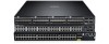
..., a Universal Serial Bus port (USB), and stacking identification LEDs. Introduction S4820T is a top-of 40Gbps with the airflow from the small vent holes above and below the ports. S4820T PSU-Side View Power Supply 0 Fan Module 0 Fan Module 1 Power Supply 1 Port Grab Handles Figure 2-2. The S4820T has 48 ports of RJ-45 10GBase-T and four ports of...
..., a Universal Serial Bus port (USB), and stacking identification LEDs. Introduction S4820T is a top-of 40Gbps with the airflow from the small vent holes above and below the ports. S4820T PSU-Side View Power Supply 0 Fan Module 0 Fan Module 1 Power Supply 1 Port Grab Handles Figure 2-2. The S4820T has 48 ports of RJ-45 10GBase-T and four ports of...
Installing the S4820T System
Page 10
... monitor • Real time clock (RTC) support • Hot-plugging redundant power supply • Current monitoring for transmitting data, storage, and server traffic. www.dell.com | support.dell.com The S4820T switch runs the Dell Force10 Operating System (FTOS), providing switching, bridging, and routing functionality for Power management • Removable fan that you can manage • Standard 1U...
... monitor • Real time clock (RTC) support • Hot-plugging redundant power supply • Current monitoring for transmitting data, storage, and server traffic. www.dell.com | support.dell.com The S4820T switch runs the Dell Force10 Operating System (FTOS), providing switching, bridging, and routing functionality for Power management • Removable fan that you can manage • Standard 1U...

Installing the S4820T System
Page 12
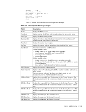
Critical system error • Blinking red - Non-critical system error (fan fail, power supply fail) TEMP LED • Off: Normal temperature • Solid red - locator function is active 12 | The S4820T Switch QSFP+ Port LEDs Feature Detailed Description Link LED • Off - fan ...Amber - Normal Operation • Blinking blue - Normal operating • Solid green - No Link • Blinking green - www.dell.com | support.dell.com Table 2-1. When one of table) DIAG LED • Off - No Link • Solid green - No Link • Blinking green ...
Critical system error • Blinking red - Non-critical system error (fan fail, power supply fail) TEMP LED • Off: Normal temperature • Solid red - locator function is active 12 | The S4820T Switch QSFP+ Port LEDs Feature Detailed Description Link LED • Off - fan ...Amber - Normal Operation • Blinking blue - Normal operating • Solid green - No Link • Blinking green - www.dell.com | support.dell.com Table 2-1. When one of table) DIAG LED • Off - No Link • Solid green - No Link • Blinking green ...


