CUV4X User Manual
Page 5
... 79 5.1 Operating Systems 79 5.1.1 Windows 98 First Time Installation 79 5.2 CUV4X Series Motherboard Support CD 80 5.3 Install ASUS PC Probe Vx.xx 81 5.4 Install PC-Cillin 98 Vx.xx 82 5.5 Install ADOBE AcroBat Reader Vx.xx 83... 86 5.9 Uninstalling Programs 86 6. SOFTWARE REFERENCE 89 6.1 ASUS PC Probe 89 6.2 YAMAHA XGStudio 94 7. CONTENTS 4.4 Advanced Menu 56 4.4.1 Chip Configuration 60 4.4.2 I/O Device Configuration 63 4.4.3 PCI Configuration 66 4.4.4 Shadow Configuration 69 4.5 Power Menu 70 4.5.1 Power Up Control 72 4.5.2 Hardware Monitor 74 4.6 Boot Menu ...
... 79 5.1 Operating Systems 79 5.1.1 Windows 98 First Time Installation 79 5.2 CUV4X Series Motherboard Support CD 80 5.3 Install ASUS PC Probe Vx.xx 81 5.4 Install PC-Cillin 98 Vx.xx 82 5.5 Install ADOBE AcroBat Reader Vx.xx 83... 86 5.9 Uninstalling Programs 86 6. SOFTWARE REFERENCE 89 6.1 ASUS PC Probe 89 6.2 YAMAHA XGStudio 94 7. CONTENTS 4.4 Advanced Menu 56 4.4.1 Chip Configuration 60 4.4.2 I/O Device Configuration 63 4.4.3 PCI Configuration 66 4.4.4 Shadow Configuration 69 4.5 Power Menu 70 4.5.1 Power Up Control 72 4.5.2 Hardware Monitor 74 4.6 Boot Menu ...
CUV4X User Manual
Page 9
Power supply is used .) • Super Multi-I/O: Provides two high... an optional remote controller. • Desktop Management Interface (DMI): Supports DMI through the onboard hardware ASUS ASIC and the bundled ASUS PC Probe. • SMBus: Features the System Management Bus interface, which allows hardware to communicate... within a standard protocol creating a higher level of compatibility. (Requires DMI-enabled components.) ASUS CUV4X User's Manual 9 FEATURES • Wake-On-Ring Connector: Supports Wake-On-Ring activity through a PCI modem card...
Power supply is used .) • Super Multi-I/O: Provides two high... an optional remote controller. • Desktop Management Interface (DMI): Supports DMI through the onboard hardware ASUS ASIC and the bundled ASUS PC Probe. • SMBus: Features the System Management Bus interface, which allows hardware to communicate... within a standard protocol creating a higher level of compatibility. (Requires DMI-enabled components.) ASUS CUV4X User's Manual 9 FEATURES • Wake-On-Ring Connector: Supports Wake-On-Ring activity through a PCI modem card...

CUV4X User Manual
Page 10
... IDE can be enabled and/or for UltraDMA/66 doubles the UltraDMA/33 burst transfer rate to 50% higher SDRAM speed at reduced power consumption of ASUS smart series motherboards meet PC'99 compliancy. With these features implemented in the OS, PCs can handle rates up to 66.6MB/s. ...The new PC'99 requirements for systems and components are based on the following high-level goals: Support for Plug and Play compatibility and power management...
... IDE can be enabled and/or for UltraDMA/66 doubles the UltraDMA/33 burst transfer rate to 50% higher SDRAM speed at reduced power consumption of ASUS smart series motherboards meet PC'99 compliancy. With these features implemented in the OS, PCs can handle rates up to 66.6MB/s. ...The new PC'99 requirements for systems and components are based on the following high-level goals: Support for Plug and Play compatibility and power management...
CUV4X User Manual
Page 11
...2.1.4 Intelligence • Auto Fan Off: The system fans will warn the user before the system resources are messages waiting in 4.5 Power Menu). With this benefit on managing their computers from their limited resources more memory and hard drive space to prevent possible application crashes.... A chassis intrusion event is monitored by the ASUS ASIC through the CPU's internal thermal diode (on remotely through the ASUS ASIC. ASUS CUV4X User's Manual 11 The system resource monitor will power off mode regardless of two states: sleep mode or soft-off...
...2.1.4 Intelligence • Auto Fan Off: The system fans will warn the user before the system resources are messages waiting in 4.5 Power Menu). With this benefit on managing their computers from their limited resources more memory and hard drive space to prevent possible application crashes.... A chassis intrusion event is monitored by the ASUS ASIC through the CPU's internal thermal diode (on remotely through the ASUS ASIC. ASUS CUV4X User's Manual 11 The system resource monitor will power off mode regardless of two states: sleep mode or soft-off...
CUV4X User Manual
Page 12
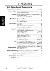
... 1 Microphone Connector (on audio model only) ... (Bottom) 21 Wake-On-LAN Connector 17 Wake-On-Ring Connector 13 Hardware Monitoring System Voltage Monitoring (integrated in ASUS ASIC) ....... 11 3 Fan Power and Speed Monitoring Connectors Power ATX Power Supply Connector 1 Special Feature Onboard LED 16 Form Factor ATX 12...
... 1 Microphone Connector (on audio model only) ... (Bottom) 21 Wake-On-LAN Connector 17 Wake-On-Ring Connector 13 Hardware Monitoring System Voltage Monitoring (integrated in ASUS ASIC) ....... 11 3 Fan Power and Speed Monitoring Connectors Power ATX Power Supply Connector 1 Special Feature Onboard LED 16 Form Factor ATX 12...

CUV4X User Manual
Page 14
...(64/72-bit, 168-pin module) DIMM Socket 3 (64/72-bit, 168-pin module) PARALLEL PORT PWR_FAN Line Out Line In Mic In ATX Power Connector VIA VT82C694Z Chipset DIP Switches DIP_SW 0 1 2 3 4 5 Row GAME_AUDIO FLOPPY IDE Secondary Primary IDE Accelerated Graphics Port (AGP PRO) MIC2 PCI... Setting PCI 5 CHA_FAN SPDIFOUT Audio Modem Riser (AMR) WOR CUV4X ISA Slot VIA VT82C686A Chipset CR2032 3V Lithium Cell CMOS Power CLRTC JEN ASUS ASIC with Hardware Monitor JTPWR USBPORT SMB IDELED CHASSIS PANEL IR COM2 Flash EEPROM (Programable BIOS) Grayed components are optional at ...
...(64/72-bit, 168-pin module) DIMM Socket 3 (64/72-bit, 168-pin module) PARALLEL PORT PWR_FAN Line Out Line In Mic In ATX Power Connector VIA VT82C694Z Chipset DIP Switches DIP_SW 0 1 2 3 4 5 Row GAME_AUDIO FLOPPY IDE Secondary Primary IDE Accelerated Graphics Port (AGP PRO) MIC2 PCI... Setting PCI 5 CHA_FAN SPDIFOUT Audio Modem Riser (AMR) WOR CUV4X ISA Slot VIA VT82C686A Chipset CR2032 3V Lithium Cell CMOS Power CLRTC JEN ASUS ASIC with Hardware Monitor JTPWR USBPORT SMB IDELED CHASSIS PANEL IR COM2 Flash EEPROM (Programable BIOS) Grayed components are optional at ...
CUV4X User Manual
Page 15
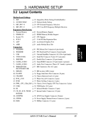
ASUS CUV4X User's Manual 15 3. H/W SETUP LayoutContents 3. HARDWARE SETUP 3.2 Layout Contents Motherboard Settings 1) JEN p. 18 JumperFree Mode Setting (Disable/Enable) 2) AUDIOCODEC p. 19 Onboard Audio Setting 3) DIP_SW 5-8 p. ... Intrusion Lead (4-1 pins) 12) WOL_CON p. 35 Wake-On-LAN Connector (3 pins) 13) WOR p. 35 Wake-On-Ring Connector (2 pins) 14) PWR_, CPU_,CHA_FAN p. 36 Chassis, Power Supply, CPU Fan Connectors (3 pins) 15) USB2 p. 36 USB Header (10-1 pins) 16) IR p. 37 Infrared Module Connector (5 pins) 17) CD_IN, AUX, VIDEO p. 37 Internal...
ASUS CUV4X User's Manual 15 3. H/W SETUP LayoutContents 3. HARDWARE SETUP 3.2 Layout Contents Motherboard Settings 1) JEN p. 18 JumperFree Mode Setting (Disable/Enable) 2) AUDIOCODEC p. 19 Onboard Audio Setting 3) DIP_SW 5-8 p. ... Intrusion Lead (4-1 pins) 12) WOL_CON p. 35 Wake-On-LAN Connector (3 pins) 13) WOR p. 35 Wake-On-Ring Connector (2 pins) 14) PWR_, CPU_,CHA_FAN p. 36 Chassis, Power Supply, CPU Fan Connectors (3 pins) 15) USB2 p. 36 USB Header (10-1 pins) 16) IR p. 37 Infrared Module Connector (5 pins) 17) CD_IN, AUX, VIDEO p. 37 Internal...
CUV4X User Manual
Page 16
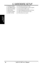
HARDWARE SETUP 21) PWR.LED (PANEL) 22) SPEAKER (PANEL) 23) MSG.LED (PANEL) 24) SMI (PANEL) 25) PWR.SW (PANEL) 26) RESET (PANEL) p. 40 System Power LED Lead (3 pins) p. 40 System Warning Speaker Connector (4 pins) p. 40 System Message LED (2 pins) p. 40 System Management Interrupt Lead (2 pins) p. 40 ATX / Soft-Off Switch Lead (2 pins) p. 40 Reset Switch Lead (2 pins) 3. 3. H/W SETUP LayoutContents 16 ASUS CUV4X User's Manual
HARDWARE SETUP 21) PWR.LED (PANEL) 22) SPEAKER (PANEL) 23) MSG.LED (PANEL) 24) SMI (PANEL) 25) PWR.SW (PANEL) 26) RESET (PANEL) p. 40 System Power LED Lead (3 pins) p. 40 System Warning Speaker Connector (4 pins) p. 40 System Message LED (2 pins) p. 40 System Management Interrupt Lead (2 pins) p. 40 ATX / Soft-Off Switch Lead (2 pins) p. 40 Reset Switch Lead (2 pins) 3. 3. H/W SETUP LayoutContents 16 ASUS CUV4X User's Manual
CUV4X User Manual
Page 17
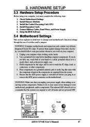
...touch both of your motherboard's function settings through the use of switches and/or jumpers. PLED CUV4X CUV4X Onboard LED ON Standby Power OFF Powered Off ASUS CUV4X User's Manual 17 Install Memory Modules 3. WARNING! Hold components by the edges and try not to a metal object, such ...as the power supply case. 3. Make sure that came with the component whenever the components are separated from static electricity, you should follow...
...touch both of your motherboard's function settings through the use of switches and/or jumpers. PLED CUV4X CUV4X Onboard LED ON Standby Power OFF Powered Off ASUS CUV4X User's Manual 17 Install Memory Modules 3. WARNING! Hold components by the edges and try not to a metal object, such ...as the power supply case. 3. Make sure that came with the component whenever the components are separated from static electricity, you should follow...

CUV4X User Manual
Page 22
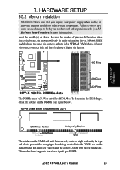
... Output) chips. • BIOS shows SDRAM memory on bootup screen. • Single-sided DIMMs come in 32, 64, 128, 256, 512MB. 22 ASUS CUV4X User's Manual HARDWARE SETUP 3.5 System Memory (DIMM) This motherboard uses only Dual Inline Memory Modules (DIMMs). H/W SETUP SystemMemory 3. double-sided come in... compatible with VCM SDRAMs. Install memory in 16, 32, 64,128, 256MB; Memory speed setup is the memory of choice for 3.3Volt (power level) unbuffered Synchronous Dynamic Random Access Memory (SDRAM) of the DIMM takes up one row on this motherboard. • For the system CPU...
... Output) chips. • BIOS shows SDRAM memory on bootup screen. • Single-sided DIMMs come in 32, 64, 128, 256, 512MB. 22 ASUS CUV4X User's Manual HARDWARE SETUP 3.5 System Memory (DIMM) This motherboard uses only Dual Inline Memory Modules (DIMMs). H/W SETUP SystemMemory 3. double-sided come in... compatible with VCM SDRAMs. Install memory in 16, 32, 64,128, 256MB; Memory speed setup is the memory of choice for 3.3Volt (power level) unbuffered Synchronous Dynamic Random Access Memory (SDRAM) of the DIMM takes up one row on this motherboard. • For the system CPU...
CUV4X User Manual
Page 23
... per DIMM. Failure to do so may cause severe damage to prevent the wrong type from being inserted into the DIMM slot on both your power supply when adding or removing memory modules or other system components. Insert the module(s) as shown. DRAM SIMM modules have a higher pin density. 88 Pins... information). You must be 3.3Volt unbuffered SDRAMs. To determine the DIMM type, check the notches on the DIMM will only fit in the orientation shown. ASUS CUV4X User's Manual 23 3.
... per DIMM. Failure to do so may cause severe damage to prevent the wrong type from being inserted into the DIMM slot on both your power supply when adding or removing memory modules or other system components. Insert the module(s) as shown. DRAM SIMM modules have a higher pin density. 88 Pins... information). You must be 3.3Volt unbuffered SDRAMs. To determine the DIMM type, check the notches on the DIMM will only fit in the orientation shown. ASUS CUV4X User's Manual 23 3.

CUV4X User Manual
Page 26
Install the necessary software drivers for your power supply when adding or removing expansion cards or other system components. Unplug your expansion card. 3. Remove your computer system's cover and the bracket plate on ... the BIOS if necessary (such as jumpers. 2. Secure the card on the slot you removed above. 5. Replace the computer system's cover. 6. H/W SETUP Expansion Cards 26 ASUS CUV4X User's Manual Failure to do so may cause severe damage to use . 3. HARDWARE SETUP 3.7 Expansion Cards WARNING! Read the documentation for your expansion card...
Install the necessary software drivers for your power supply when adding or removing expansion cards or other system components. Unplug your expansion card. 3. Remove your computer system's cover and the bracket plate on ... the BIOS if necessary (such as jumpers. 2. Secure the card on the slot you removed above. 5. Replace the computer system's cover. 6. H/W SETUP Expansion Cards 26 ASUS CUV4X User's Manual Failure to do so may cause severe damage to use . 3. HARDWARE SETUP 3.7 Expansion Cards WARNING! Read the documentation for your expansion card...
CUV4X User Manual
Page 28
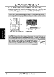
...-pin bay Rib (inside slot) CUV4X CUV4X Accelerated Graphics Port (AGP PRO) TOP VIEW 28-pin bay Rib CAUTION! Use a rigid tip, such as an ASUS AGP-V6800DDR/64M. 3. removing may cause these cards to shift, which may cause damage to dislodge and remove the tab from the bay. To avoid...
...-pin bay Rib (inside slot) CUV4X CUV4X Accelerated Graphics Port (AGP PRO) TOP VIEW 28-pin bay Rib CAUTION! Use a rigid tip, such as an ASUS AGP-V6800DDR/64M. 3. removing may cause these cards to shift, which may cause damage to dislodge and remove the tab from the bay. To avoid...

CUV4X User Manual
Page 30
Pin 1 is not detected, expansion cards can use a DIN to mini DIN adapter on the connectors. If one is for connectors or power sources. H/W SETUP Connectors 2) PS/2 Keyboard Connector (Purple 6-pin PS2KBMS) This connection is detected. This connector will cause damage to Pin 1 on ... side on floppy disk drives. These are used for a standard keyboard using an PS/2 plug (mini DIN). PS/2 Keyboard (6-pin female) 30 ASUS CUV4X User's Manual Some pins are clearly distinguished from the first connector. 1) PS/2 Mouse Connector (Green 6-pin PS2KBMS) The system will direct IRQ12...
Pin 1 is not detected, expansion cards can use a DIN to mini DIN adapter on the connectors. If one is for connectors or power sources. H/W SETUP Connectors 2) PS/2 Keyboard Connector (Purple 6-pin PS2KBMS) This connection is detected. This connector will cause damage to Pin 1 on ... side on floppy disk drives. These are used for a standard keyboard using an PS/2 plug (mini DIN). PS/2 Keyboard (6-pin female) 30 ASUS CUV4X User's Manual Some pins are clearly distinguished from the first connector. 1) PS/2 Mouse Connector (Green 6-pin PS2KBMS) The system will direct IRQ12...
CUV4X User Manual
Page 32
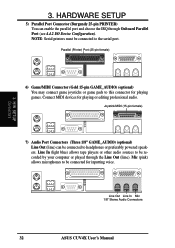
... Line Out (lime). H/W SETUP Connectors 6) Game/MIDI Connector (Gold 15-pin GAME_AUDIO) (optional) You may connect game joysticks or game pads to headphones or preferably powered speakers. Line Out Line In Mic 1/8" Stereo Audio Connectors 32...
... Line Out (lime). H/W SETUP Connectors 6) Game/MIDI Connector (Gold 15-pin GAME_AUDIO) (optional) You may connect game joysticks or game pads to headphones or preferably powered speakers. Line Out Line In Mic 1/8" Stereo Audio Connectors 32...
CUV4X User Manual
Page 33
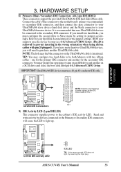
...an IDE drive and another on the UltraDMA/66 cable is recommended that non-UltraDMA/66 devices be both Masters with pin 20 plugged). ASUS CUV4X User's Manual 33 3. Read and write activity by setting its jumper accordingly. You may configure two hard disks to be connected ...disks, you will cause the LED to the secondary IDE connector. CUV4X PIN 1 CUV4X IDE Connectors 9) IDE Activity LED (2-pin IDELED) This connector supplies power to PIN 1. NOTE: The hole near the blue connector on a SCSI drive and select the boot disk through 4.4.1 Advanced CMOS Setup. NOTE: Orient...
...an IDE drive and another on the UltraDMA/66 cable is recommended that non-UltraDMA/66 devices be both Masters with pin 20 plugged). ASUS CUV4X User's Manual 33 3. Read and write activity by setting its jumper accordingly. You may configure two hard disks to be connected ...disks, you will cause the LED to the secondary IDE connector. CUV4X PIN 1 CUV4X IDE Connectors 9) IDE Activity LED (2-pin IDELED) This connector supplies power to PIN 1. NOTE: The hole near the blue connector on a SCSI drive and select the boot disk through 4.4.1 Advanced CMOS Setup. NOTE: Orient...
CUV4X User Manual
Page 35
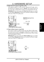
... received through the COM port. H/W SETUP Connectors CUV4X CUV4X Wake-On-Ring Connector WOR RI# Ground 2 1 ASUS CUV4X User's Manual 35 IMPORTANT: Requires an ATX power supply with a Wake-On-Ring output. Appendix). The connector powers up the system when a ringup packet or signal is detected through the internal modem card. IMPORTANT: This...
... received through the COM port. H/W SETUP Connectors CUV4X CUV4X Wake-On-Ring Connector WOR RI# Ground 2 1 ASUS CUV4X User's Manual 35 IMPORTANT: Requires an ATX power supply with a Wake-On-Ring output. Appendix). The connector powers up the system when a ringup packet or signal is detected through the internal modem card. IMPORTANT: This...
CUV4X User Manual
Page 36
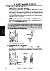
... onboard heat sink(s) instead of the expansion slots. The CPU and/or motherboard will overheat if there is to be different. HARDWARE SETUP 14) Power Supply, CPU, Chassis Fan Connectors (3-pin PWR_FAN, CPU_FAN1, CHA_FAN) These connectors support cooling fans of the connector. The Rotations per Minute (RPM)... to the motherboard and/or the CPU fan if these pins. The red wire should be positive, while the black should be monitored using ASUS PC Probe (see 6. WARNING! Depending on your chassis. SOFTWARE REFERENCE). These are not jumpers, do not place jumper caps over these pins...
... onboard heat sink(s) instead of the expansion slots. The CPU and/or motherboard will overheat if there is to be different. HARDWARE SETUP 14) Power Supply, CPU, Chassis Fan Connectors (3-pin PWR_FAN, CPU_FAN1, CHA_FAN) These connectors support cooling fans of the connector. The Rotations per Minute (RPM)... to the motherboard and/or the CPU fan if these pins. The red wire should be positive, while the black should be monitored using ASUS PC Probe (see 6. WARNING! Depending on your chassis. SOFTWARE REFERENCE). These are not jumpers, do not place jumper caps over these pins...

CUV4X User Manual
Page 37
... whether UART2 is directed for use Consumer Infrared (CIR) power up. Wake On PS2 KB/Mouse in Back View and connect a ribbon cable from such sound sources as a CD-ROM, TV tuner, or MPEG card. 3. This module mounts to Modem) MODEM ASUS CUV4X User's Manual 37 Use the five pins as a... speaker) between the onboard audio and a voice modem card. +5V (NC) IRRX GND IRTX 3. It also allows the sharing of mono_in (such as a phone) and mono_out (such as shown in 4.5.1 Power Up Control must also configure ...
... whether UART2 is directed for use Consumer Infrared (CIR) power up. Wake On PS2 KB/Mouse in Back View and connect a ribbon cable from such sound sources as a CD-ROM, TV tuner, or MPEG card. 3. This module mounts to Modem) MODEM ASUS CUV4X User's Manual 37 Use the five pins as a... speaker) between the onboard audio and a voice modem card. +5V (NC) IRRX GND IRTX 3. It also allows the sharing of mono_in (such as a phone) and mono_out (such as shown in 4.5.1 Power Up Control must also configure ...
CUV4X User Manual
Page 38
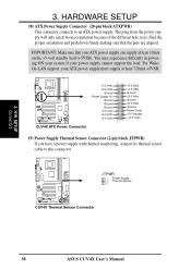
... CUV4X CUV4X Thermal Sensor Connector 38 ASUS CUV4X User's Manual H/W SETUP Connectors 3. Find the proper orientation and push down firmly making sure that your ATX power supply can supply at least 720mA +5VSB. CUV4X CUV4X ATX Power Connector +3.3 Volts -12.0 Volts Ground Power Supply On Ground Ground Ground -5.0 ...because of the different hole sizes. For WakeOn-LAN support, your power supply cannot support the load. The plug from the power supply will only insert in powering ON your system if your ATX power supply must supply at least 10mA on the +5-volt standby lead ...
... CUV4X CUV4X Thermal Sensor Connector 38 ASUS CUV4X User's Manual H/W SETUP Connectors 3. Find the proper orientation and push down firmly making sure that your ATX power supply can supply at least 720mA +5VSB. CUV4X CUV4X ATX Power Connector +3.3 Volts -12.0 Volts Ground Power Supply On Ground Ground Ground -5.0 ...because of the different hole sizes. For WakeOn-LAN support, your power supply cannot support the load. The plug from the power supply will only insert in powering ON your system if your ATX power supply must supply at least 10mA on the +5-volt standby lead ...


