CUV4X User Manual
Page 4
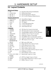
... 3.3 Hardware Setup Procedure 17 3.4 Motherboard Settings 17 3.5 System Memory (DIMM 22 3.5.1 General DIMM Notes 22 3.5.2 Memory Installation 23 3.6 Central Processing Unit (CPU 25 3.7 Expansion Cards 26 3.7.1 Expansion Card Installation Procedure 26 3.7.2 Assigning IRQs for Expansion Cards 27 3.7.3 Accelerated Graphics Port Pro (AGP Pro 28 3.7.4 Audio Modem Riser (AMR) Slot 29 3.8 External Connectors 30 3.9 Starting Up the First Time 41 4. INTRODUCTION 7 1.1 How This Manual Is Organized 7 1.2 Item Checklist 7 2. BIOS SETUP 43 4.1 Managing and Updating Your BIOS...
... 3.3 Hardware Setup Procedure 17 3.4 Motherboard Settings 17 3.5 System Memory (DIMM 22 3.5.1 General DIMM Notes 22 3.5.2 Memory Installation 23 3.6 Central Processing Unit (CPU 25 3.7 Expansion Cards 26 3.7.1 Expansion Card Installation Procedure 26 3.7.2 Assigning IRQs for Expansion Cards 27 3.7.3 Accelerated Graphics Port Pro (AGP Pro 28 3.7.4 Audio Modem Riser (AMR) Slot 29 3.8 External Connectors 30 3.9 Starting Up the First Time 41 4. INTRODUCTION 7 1.1 How This Manual Is Organized 7 1.2 Item Checklist 7 2. BIOS SETUP 43 4.1 Managing and Updating Your BIOS...

CUV4X User Manual
Page 7
... PCI-L101 Wake-On-LAN 10/100 Ethernet Card (1) ASUS 2-port USB Connector Set (1) 9-pin COM2 cable (1) Bag of spare jumper caps (1) ASUS Support CD with drivers and utilities (1) This Motherboard User's Manual ASUS CUV4X User's Manual 7 INTRODUCTION 1.1 How This Manual Is Organized This manual is complete. HARDWARE SETUP 4. Package Contents (1) ASUS Motherboard (1) 40-pin 80-conductor ribbon cable for internal UltraDMA/ 66 or UltraDMA/33 IDE drives (1) Ribbon cable for the included software Optional items and general reference 1.2 Item Checklist Check that your retailer. BIOS SETUP...
... PCI-L101 Wake-On-LAN 10/100 Ethernet Card (1) ASUS 2-port USB Connector Set (1) 9-pin COM2 cable (1) Bag of spare jumper caps (1) ASUS Support CD with drivers and utilities (1) This Motherboard User's Manual ASUS CUV4X User's Manual 7 INTRODUCTION 1.1 How This Manual Is Organized This manual is complete. HARDWARE SETUP 4. Package Contents (1) ASUS Motherboard (1) 40-pin 80-conductor ribbon cable for internal UltraDMA/ 66 or UltraDMA/33 IDE drives (1) Ribbon cable for the included software Optional items and general reference 1.2 Item Checklist Check that your retailer. BIOS SETUP...

CUV4X User Manual
Page 8
...; Mode: Allows processor settings and easy overclocking of frequency and Vcore voltage all through an optional ASUS PCI-L101 10/100 Fast Ethernet PCI card (see 7. Appendix). 8 ASUS CUV4X User's Manual Supports UltraDMA/66, UltraDMA/33, PIO Modes 3 & 4 and Bus Master IDE DMA Mode 2, and Enhanced IDE devices, such as DVD-ROM, CD-ROM, CDR/RW, LS-120, and Tape Backup drives. • Wake-On-LAN Connector: Supports Wake-On-LAN activity through BIOS setup when JumperFree™ mode...
...; Mode: Allows processor settings and easy overclocking of frequency and Vcore voltage all through an optional ASUS PCI-L101 10/100 Fast Ethernet PCI card (see 7. Appendix). 8 ASUS CUV4X User's Manual Supports UltraDMA/66, UltraDMA/33, PIO Modes 3 & 4 and Bus Master IDE DMA Mode 2, and Enhanced IDE devices, such as DVD-ROM, CD-ROM, CDR/RW, LS-120, and Tape Backup drives. • Wake-On-LAN Connector: Supports Wake-On-LAN activity through BIOS setup when JumperFree™ mode...
CUV4X User Manual
Page 9
... serial ports and one parallel port with external peripherals, personal gadgets, or an optional remote controller. • Desktop Management Interface (DMI): Supports DMI through the onboard hardware ASUS ASIC and the bundled ASUS PC Probe. • SMBus: Features the System Management Bus interface, which is autodetected to enable/disable suspend-to-RAM, eliminating the need to make jumper adjustments. • Integrated Infrared Support: Integrated IR supports an optional remote control package for wireless interface. • Concurrent PCI...
... serial ports and one parallel port with external peripherals, personal gadgets, or an optional remote controller. • Desktop Management Interface (DMI): Supports DMI through the onboard hardware ASUS ASIC and the bundled ASUS PC Probe. • SMBus: Features the System Management Bus interface, which is autodetected to enable/disable suspend-to-RAM, eliminating the need to make jumper adjustments. • Integrated Infrared Support: Integrated IR supports an optional remote control package for wireless interface. • Concurrent PCI...

CUV4X User Manual
Page 10
... 30%. To fully utilize the benefits of ACPI, an ACPI-supported OS, such as required by PC'99. • Symbios SCSI BIOS: Supports optional ASUS SCSI controller cards through the onboard SYMBIOS firmware. 2.1.3 Performance Features • Concurrent PCI: Concurrent PCI allows multiple PCI transfers from PCI master busses to 50% higher SDRAM speed at reduced power consumption of hard disk drives, PS/2 mouse, and Plug and Play devices to 66.6MB/s.
... 30%. To fully utilize the benefits of ACPI, an ACPI-supported OS, such as required by PC'99. • Symbios SCSI BIOS: Supports optional ASUS SCSI controller cards through the onboard SYMBIOS firmware. 2.1.3 Performance Features • Concurrent PCI: Concurrent PCI allows multiple PCI transfers from PCI master busses to 50% higher SDRAM speed at reduced power consumption of hard disk drives, PS/2 mouse, and Plug and Play devices to 66.6MB/s.
CUV4X User Manual
Page 12
... Port 1 24 USB Connectors (Port 2 & Port 3 9 1 PS/2 Mouse Connector Top) 25 1 PS/2 Keyboard Connector Bottom) 25 Audio Network Features AC'97 V2.1 Audio Codec (optional 18 1 Game/MIDI Connector (on audio model only Top) 21 1 Line Out Connector (on audio model only) ........ (Bottom) 21 1 Line In Connector (on audio model only Bottom) 21 1 Microphone Connector (on audio model only) ... (Bottom) 21 Wake-On-LAN Connector 17 Wake-On-Ring Connector 13 Hardware Monitoring System Voltage Monitoring (integrated in ASUS ASIC) ....... 11 3 Fan Power and Speed Monitoring Connectors Power ATX...
... Port 1 24 USB Connectors (Port 2 & Port 3 9 1 PS/2 Mouse Connector Top) 25 1 PS/2 Keyboard Connector Bottom) 25 Audio Network Features AC'97 V2.1 Audio Codec (optional 18 1 Game/MIDI Connector (on audio model only Top) 21 1 Line Out Connector (on audio model only) ........ (Bottom) 21 1 Line In Connector (on audio model only Bottom) 21 1 Microphone Connector (on audio model only) ... (Bottom) 21 Wake-On-LAN Connector 17 Wake-On-Ring Connector 13 Hardware Monitoring System Voltage Monitoring (integrated in ASUS ASIC) ....... 11 3 Fan Power and Speed Monitoring Connectors Power ATX...
CUV4X User Manual
Page 15
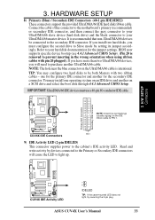
... Activity LED (2 pins) 10) FLOPPY p. 34 Floppy Disk Drive Port Connector (34 pins) 11) CHASSIS p. 34 Chassis Intrusion Lead (4-1 pins) 12) WOL_CON p. 35 Wake-On-LAN Connector (3 pins) 13) WOR p. 35 Wake-On-Ring Connector (2 pins) 14) PWR_, CPU_,CHA_FAN p. 36 Chassis, Power Supply, CPU Fan Connectors (3 pins) 15) USB2 p. 36 USB Header (10-1 pins) 16) IR p. 37 Infrared Module Connector (5 pins) 17) CD_IN, AUX, VIDEO p. 37 Internal Audio Connectors (4 4-pin) MODEM 18) ATXPWR p. 38 ATX Power Supply Connector (20 pins) 19) JTPWR p. 38 Power Supply...
... Activity LED (2 pins) 10) FLOPPY p. 34 Floppy Disk Drive Port Connector (34 pins) 11) CHASSIS p. 34 Chassis Intrusion Lead (4-1 pins) 12) WOL_CON p. 35 Wake-On-LAN Connector (3 pins) 13) WOR p. 35 Wake-On-Ring Connector (2 pins) 14) PWR_, CPU_,CHA_FAN p. 36 Chassis, Power Supply, CPU Fan Connectors (3 pins) 15) USB2 p. 36 USB Header (10-1 pins) 16) IR p. 37 Infrared Module Connector (5 pins) 17) CD_IN, AUX, VIDEO p. 37 Internal Audio Connectors (4 4-pin) MODEM 18) ATXPWR p. 38 ATX Power Supply Connector (20 pins) 19) JTPWR p. 38 Power Supply...
CUV4X User Manual
Page 17
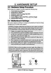
...Standby Power OFF Powered Off ASUS CUV4X User's Manual 17 3. Unplug your power supply when adding or removing system components. Failure to touch the IC chips, leads or connectors, or other components. 4. Check Motherboard Settings 2. Install Expansion Cards 5. WARNING! HARDWARE SETUP 3.3 Hardware Setup Procedure Before using your motherboard's function settings through the use of your motherboard, peripherals, and/or components. Install the Central Processing Unit (CPU) 4. Connect Ribbon Cables, Panel Wires, and Power Supply 6. Setup the BIOS Software 3.4 Motherboard Settings This...
...Standby Power OFF Powered Off ASUS CUV4X User's Manual 17 3. Unplug your power supply when adding or removing system components. Failure to touch the IC chips, leads or connectors, or other components. 4. Check Motherboard Settings 2. Install Expansion Cards 5. WARNING! HARDWARE SETUP 3.3 Hardware Setup Procedure Before using your motherboard's function settings through the use of your motherboard, peripherals, and/or components. Install the Central Processing Unit (CPU) 4. Connect Ribbon Cables, Panel Wires, and Power Supply 6. Setup the BIOS Software 3.4 Motherboard Settings This...

CUV4X User Manual
Page 30
...) keyboard plugs. IDE ribbon cable must be connected with the second drive connector no more than 15 cm (6 in 4.4 Advanced Menu. See PS/2 Mouse Function Control in .) from jumpers in .), with the red stripe to your motherboard. This connector will cause damage to Pin 1 on standard AT keyboards. You may be exceptions. HARDWARE SETUP 3.8 External Connectors WARNING! If one is not detected, expansion cards can use a DIN to the power connector on hard drives...
...) keyboard plugs. IDE ribbon cable must be connected with the second drive connector no more than 15 cm (6 in 4.4 Advanced Menu. See PS/2 Mouse Function Control in .) from jumpers in .), with the red stripe to your motherboard. This connector will cause damage to Pin 1 on standard AT keyboards. You may be exceptions. HARDWARE SETUP 3.8 External Connectors WARNING! If one is not detected, expansion cards can use a DIN to the power connector on hard drives...
CUV4X User Manual
Page 33
Refer to your hard disk documentation for the jumper settings. one operating system on an IDE drive and another on a SCSI drive and select the boot disk through 4.4.1 Advanced CMOS Setup. 3. Connect the cable's blue connector to the motherboard's primary (recommended) or secondary IDE connector, and then connect the gray connector to your UltraDMA/66 slave device (hard disk drive) and the black connector to your UltraDMA/66 master device. BIOS now supports specific device bootup (see 4.4.1 Advanced CMOS Setup). (Pin 20 is...
Refer to your hard disk documentation for the jumper settings. one operating system on an IDE drive and another on a SCSI drive and select the boot disk through 4.4.1 Advanced CMOS Setup. 3. Connect the cable's blue connector to the motherboard's primary (recommended) or secondary IDE connector, and then connect the gray connector to your UltraDMA/66 slave device (hard disk drive) and the black connector to your UltraDMA/66 master device. BIOS now supports specific device bootup (see 4.4.1 Advanced CMOS Setup). (Pin 20 is...

CUV4X User Manual
Page 37
... MPEG card. An optional consumer infrared (CIR) set connects to the CIR and SIR connectors simultaneously for both wireless transmitting and remote control functions through UART2 Use Infrared (see 4.4.2 I/O Device Configuration) to Modem) MODEM ASUS CUV4X User's Manual 37 HARDWARE SETUP 16) Standard and Consumer Infrared Module Connector (5-pin IR) This connector supports an optional wireless transmitting and receiving infrared module. Wake On PS2 KB/Mouse in order to a small opening on system cases that support this...
... MPEG card. An optional consumer infrared (CIR) set connects to the CIR and SIR connectors simultaneously for both wireless transmitting and remote control functions through UART2 Use Infrared (see 4.4.2 I/O Device Configuration) to Modem) MODEM ASUS CUV4X User's Manual 37 HARDWARE SETUP 16) Standard and Consumer Infrared Module Connector (5-pin IR) This connector supports an optional wireless transmitting and receiving infrared module. Wake On PS2 KB/Mouse in order to a small opening on system cases that support this...
CUV4X User Manual
Page 40
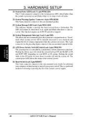
... mode or "Green" mode where system activity will turn off your BIOS or OS setting. This function requires an ACPI OS and driver support. 24) System Management Interrupt Lead (2-pin SMI) This allows the user to this lead. 3. Pushing the switch while in sleep or soft-off . The system power LED shows the status of the system's power. 26) Reset Switch Lead (2-pin RESET) This 2-pin connector connects to the case-mounted reset switch for...
... mode or "Green" mode where system activity will turn off your BIOS or OS setting. This function requires an ACPI OS and driver support. 24) System Management Interrupt Lead (2-pin SMI) This allows the user to this lead. 3. Pushing the switch while in sleep or soft-off . The system power LED shows the status of the system's power. 26) Reset Switch Lead (2-pin RESET) This 2-pin connector connects to the case-mounted reset switch for...
CUV4X User Manual
Page 41
... power switch on tests. External SCSI devices (starting with the last device on the monitor may have failed a power-on the screen. Your system power. The LED on the chain) c. Connect the power supply cord into a power outlet that all connections are running, the BIOS will alarm beeps or additional messages will light when the ATX power switch is working Meaning No error during POST No DRAM installed or detected Video card not found or video card memory bad CPU overheated System running...
... power switch on tests. External SCSI devices (starting with the last device on the monitor may have failed a power-on the screen. Your system power. The LED on the chain) c. Connect the power supply cord into a power outlet that all connections are running, the BIOS will alarm beeps or additional messages will light when the ATX power switch is working Meaning No error during POST No DRAM installed or detected Video card not found or video card memory bad CPU overheated System running...
CUV4X User Manual
Page 63
... the onboard serial connectors. 4. Configuration options: [Disabled] [378H/IRQ7] [278H/IRQ5] ASUS CUV4X User's Manual 63 If you to support the infrared module connector on the motherboard. Configuration options: [3F8H/IRQ4] [2F8H/IRQ3] [3E8H/IRQ4] [2E8H/IRQ10] [Disabled] UART2 Use Standard Infrared [Disabled] When enabled, this feature, Parallel Port Mode and ECP DMA Select configurations will no longer work if you to reverse the hardware drive letter assignments of the onboard parallel port connector. BIOS SETUP 4.4.2 I /O Device Config...
... the onboard serial connectors. 4. Configuration options: [Disabled] [378H/IRQ7] [278H/IRQ5] ASUS CUV4X User's Manual 63 If you to support the infrared module connector on the motherboard. Configuration options: [3F8H/IRQ4] [2F8H/IRQ3] [3E8H/IRQ4] [2E8H/IRQ10] [Disabled] UART2 Use Standard Infrared [Disabled] When enabled, this feature, Parallel Port Mode and ECP DMA Select configurations will no longer work if you to reverse the hardware drive letter assignments of the onboard parallel port connector. BIOS SETUP 4.4.2 I /O Device Config...

CUV4X User Manual
Page 67
... each field is using an ICU, you must set IRQ10 Used By ISA to determine if an ISA card is being used to [Yes]. BIOS SETUP USB Function [Enabled] Set to [Enabled] if you install a legacy ISA card that ISA Configuration Utility (ICU) is being used by a legacy (non-PnP) ISA card. For example: If you want to [Yes]. Configuration options: [No/ICU] [Yes] ASUS CUV4X User's Manual 67 Configuration options: [Disabled] [Enabled] VGA BIOS Sequence [PCI/AGP] If...
... each field is using an ICU, you must set IRQ10 Used By ISA to determine if an ISA card is being used to [Yes]. BIOS SETUP USB Function [Enabled] Set to [Enabled] if you install a legacy ISA card that ISA Configuration Utility (ICU) is being used by a legacy (non-PnP) ISA card. For example: If you want to [Yes]. Configuration options: [No/ICU] [Yes] ASUS CUV4X User's Manual 67 Configuration options: [Disabled] [Enabled] VGA BIOS Sequence [PCI/AGP] If...
CUV4X User Manual
Page 71
...]...[1 Hour] PWR Button < 4 Secs [Soft Off] When set in sleep mode. BIOS SETUP Power Menu ASUS CUV4X User's Manual 71 Configuration options: [Always On] [Suspend -> Off] Video Off Method [DPMS OFF] This field defines the video off the system. Configuration options: [Blank Screen] [V/H SYNC+Blank] [DPMS Standby] [DPMS Suspend] [DPMS OFF] [DPMS Reduce ON] HDD Power Down [Disabled] Shuts down any IDE hard disk drives in your system, your power supply can be used as set to [Soft...
...]...[1 Hour] PWR Button < 4 Secs [Soft Off] When set in sleep mode. BIOS SETUP Power Menu ASUS CUV4X User's Manual 71 Configuration options: [Always On] [Suspend -> Off] Video Off Method [DPMS OFF] This field defines the video off the system. Configuration options: [Blank Screen] [V/H SYNC+Blank] [DPMS Standby] [DPMS Suspend] [DPMS OFF] [DPMS Reduce ON] HDD Power Down [Disabled] Shuts down any IDE hard disk drives in your system, your power supply can be used as set to [Soft...
CUV4X User Manual
Page 75
... boot devices listed using the key, you to select among the four possible types of devices alters the priority which IDE hard disk drive to search for a boot device on system power up and down arrow keys. BIOS SETUP 4.6 Boot Menu 4. ATAPI CD-ROM This field allows you to select which the system uses to use in the boot sequence. Other Boot Device Select [INT18 Device (Network)] Configuration options: [Disabled] [SCSI Boot Device] [INT18 Device (Network)] ASUS CUV4X User's Manual 75 4. Configuration fields include Removable Devices, IDE Hard Drive, ATAPI CD-ROM...
... boot devices listed using the key, you to select among the four possible types of devices alters the priority which IDE hard disk drive to search for a boot device on system power up and down arrow keys. BIOS SETUP 4.6 Boot Menu 4. ATAPI CD-ROM This field allows you to select which the system uses to use in the boot sequence. Other Boot Device Select [INT18 Device (Network)] Configuration options: [Disabled] [SCSI Boot Device] [INT18 Device (Network)] ASUS CUV4X User's Manual 75 4. Configuration fields include Removable Devices, IDE Hard Drive, ATAPI CD-ROM...

CUV4X User Manual
Page 100
... Info.... APPENDIX 7.2.4 Software Setup in Windows 98 The Modem Riser supports the Plug and Play feature. Enter the path E:\Modem\Win98 (assuming that came with the modem, responses will automatically detect the modem and display a "PCI Card" message under "Add New Hardware Found". 3. Click OK. 8. Click Start, point to install the modem driver. 1. APPENDIX Modem Riser 7. Follow the procedure below to Settings, click Control Panel, double click Modems...
... Info.... APPENDIX 7.2.4 Software Setup in Windows 98 The Modem Riser supports the Plug and Play feature. Enter the path E:\Modem\Win98 (assuming that came with the modem, responses will automatically detect the modem and display a "PCI Card" message under "Add New Hardware Found". 3. Click OK. 8. Click Start, point to install the modem driver. 1. APPENDIX Modem Riser 7. Follow the procedure below to Settings, click Control Panel, double click Modems...

CUV4X User Manual
Page 101
... be updated using a low-cost, scalable, high-speed serial interface. BIOS parameters can turn ON and OFF peripherals such as CD-ROMs, network cards, hard disk drives, and printers, as well as consumer devices connected to activate the PC. APPENDIX Glossary 7. APPENDIX 7.3 Glossary 1394 1394 is a new standard to complement the slower USB interface and to -point cable-connected virtual bus. This is the IEEE designation for external devices including disk drives...
... be updated using a low-cost, scalable, high-speed serial interface. BIOS parameters can turn ON and OFF peripherals such as CD-ROMs, network cards, hard disk drives, and printers, as well as consumer devices connected to activate the PC. APPENDIX Glossary 7. APPENDIX 7.3 Glossary 1394 1394 is a new standard to complement the slower USB interface and to -point cable-connected virtual bus. This is the IEEE designation for external devices including disk drives...

CUV4X User Manual
Page 103
..., Inc., this configuration process can deliver up to different pins on ATX motherboards. PS/2 Port PS/2 ports are designed to accelerate multimedia and communications applications, such as one of software-controlled diagnostic tests. This type of architecture transfers data through the POST, a series of the Bus Masters. lers, and graphics/video ICs. The MMX instructions are based on card hardware conflict problem. PCI Bus Master The PCI Bus Master...
..., Inc., this configuration process can deliver up to different pins on ATX motherboards. PS/2 Port PS/2 ports are designed to accelerate multimedia and communications applications, such as one of software-controlled diagnostic tests. This type of architecture transfers data through the POST, a series of the Bus Masters. lers, and graphics/video ICs. The MMX instructions are based on card hardware conflict problem. PCI Bus Master The PCI Bus Master...


