User Manual
Page 5
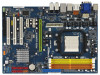
...ASRock K10N78-1394 / K10N78 motherboard, a reliable motherboard produced under ASRock's consistently stringent quality control. www.asrock.com/support/index.asp 1.1 Package Contents ASRock K10N78-1394 / K10N78 Motherboard (ATX Form Factor: 12.0-in x 8.4-in, 30.5 cm x 21.3 cm) ASRock K10N78-1394 / K10N78 Quick Installation Guide ASRock K10N78-1394 / K10N78... 1. It delivers excellent performance with robust design conforming to ASRock's commitment to the hardware installation. Chapter 3 and 4 contain the configuration guide to BIOS setup and information of the motherboard and step-bystep guide ...
...ASRock K10N78-1394 / K10N78 motherboard, a reliable motherboard produced under ASRock's consistently stringent quality control. www.asrock.com/support/index.asp 1.1 Package Contents ASRock K10N78-1394 / K10N78 Motherboard (ATX Form Factor: 12.0-in x 8.4-in, 30.5 cm x 21.3 cm) ASRock K10N78-1394 / K10N78 Quick Installation Guide ASRock K10N78-1394 / K10N78... 1. It delivers excellent performance with robust design conforming to ASRock's commitment to the hardware installation. Chapter 3 and 4 contain the configuration guide to BIOS setup and information of the motherboard and step-bystep guide ...
User Manual
Page 23
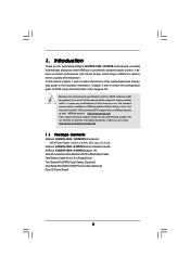
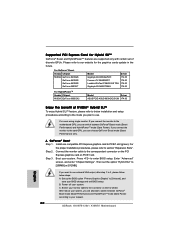
...] or [512MB]. A. Step 3. If you can choose GeForce® Boost mode (Boost Performance) only. C. Supported PCI Express Card for the graphics cards update in the future. Set up the BIOS option "Primary Graphics Display" to [Onboard], and save your monitor cable to the motherboard GPU, you connect the monitor to our website...
...] or [512MB]. A. Step 3. If you can choose GeForce® Boost mode (Boost Performance) only. C. Supported PCI Express Card for the graphics cards update in the future. Set up the BIOS option "Primary Graphics Display" to [Onboard], and save your monitor cable to the motherboard GPU, you connect the monitor to our website...
User Manual
Page 24
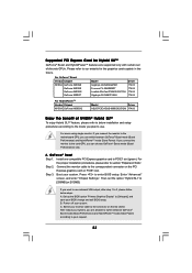
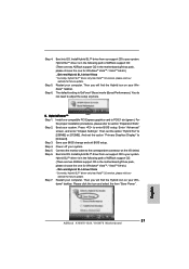
...update. Enter "Advanced" screen, and enter "Chipset Settings". And set the option "Hybrid SLI" to PCIE1 slot (green). Boot into OS. Step 2. Then set the option "Primary Graphics Display" to your BIOS change and exit BIOS setup. Save your system. Step 4. Hybrid SLITM driver is in the following path of ASRock... support CD: (There are two ASRock support CD in the motherboard gift box pack, please choose ...
...update. Enter "Advanced" screen, and enter "Chipset Settings". And set the option "Hybrid SLI" to PCIE1 slot (green). Boot into OS. Step 2. Then set the option "Primary Graphics Display" to your BIOS change and exit BIOS setup. Save your system. Step 4. Hybrid SLITM driver is in the following path of ASRock... support CD: (There are two ASRock support CD in the motherboard gift box pack, please choose ...
User Manual
Page 25
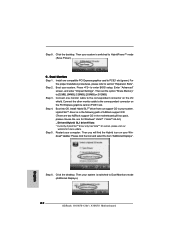
...[128MB], [256MB] or [512MB]. Boot into OS. dows® taskbar. Then your system is in the following path of ASRock support CD: (There are two ASRock support CD in the motherboard gift box pack, please choose the one compatible PCI Express graphics card to section "Expansion Slots". Step..." to enter BIOS setup. Connect one monitor cable to HybridPowerTM mode (Save Power). Install one for Windows® VistaTM / VistaTM 64-bit.) ..\Drivers\Hybrid SLI driver\Vista * Currently, Hybrid SLITM driver only has VistaTM 32 version, please visit our website for future update. Hybrid SLITM ...
...[128MB], [256MB] or [512MB]. Boot into OS. dows® taskbar. Then your system is in the following path of ASRock support CD: (There are two ASRock support CD in the motherboard gift box pack, please choose the one compatible PCI Express graphics card to section "Expansion Slots". Step..." to enter BIOS setup. Connect one monitor cable to HybridPowerTM mode (Save Power). Install one for Windows® VistaTM / VistaTM 64-bit.) ..\Drivers\Hybrid SLI driver\Vista * Currently, Hybrid SLITM driver only has VistaTM 32 version, please visit our website for future update. Hybrid SLITM ...
User Manual
Page 30
... 5 seconds. However, please do the clear-CMOS action. 30 To clear and reset the system parameters to clear the CMOS when you just finish updating the BIOS, you update the BIOS. Jumper Setting PS2_USB_PW1 1_2 2_3 Short pin2, pin3 to enable (see p.13/14, No. 9) 1_2 2_3 Default Clear CMOS Note: CLRCMOS1 allows you...
... 5 seconds. However, please do the clear-CMOS action. 30 To clear and reset the system parameters to clear the CMOS when you just finish updating the BIOS, you update the BIOS. Jumper Setting PS2_USB_PW1 1_2 2_3 Short pin2, pin3 to enable (see p.13/14, No. 9) 1_2 2_3 Default Clear CMOS Note: CLRCMOS1 allows you...

User Manual
Page 51
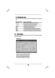
... may not exactly match what you see on the system chassis. Because the BIOS software is constantly being updated, the following BIOS setup screens and descriptions are for reference purpose only, and they may run the BIOS SETUP UTILITY when you wish to get into the sub screen. 51 If... you start up the security features Exit To exit the current screen or the BIOS SETUP UTILITY...
... may not exactly match what you see on the system chassis. Because the BIOS software is constantly being updated, the following BIOS setup screens and descriptions are for reference purpose only, and they may run the BIOS SETUP UTILITY when you wish to get into the sub screen. 51 If... you start up the security features Exit To exit the current screen or the BIOS SETUP UTILITY...
User Manual
Page 52
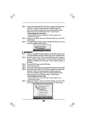
... Monitor Boot Security Exit System Overview System Time System Date [14:00:09] [Fri 07/25/2008] BIOS Version : K10N78-1394 P1.00 Processor Type : AMD Phenom (tm) 9750 Quad-Core Processor (64bit) Processor Speed : 2400MHz Microcode Update : 100F23/1000065 L1 Cache Size : 512KB L2 Cache Size : 512KB L3 Cache Size : 2048KB Total Memory...item to specify the system date. 52 3.1.2Navigation Keys Please check the following table for all the settings To save changes and exit the BIOS SETUP UTILITY To jump to the Exit Screen or exit the current screen 3.2 Main Screen When you enter the...
... Monitor Boot Security Exit System Overview System Time System Date [14:00:09] [Fri 07/25/2008] BIOS Version : K10N78-1394 P1.00 Processor Type : AMD Phenom (tm) 9750 Quad-Core Processor (64bit) Processor Speed : 2400MHz Microcode Update : 100F23/1000065 L1 Cache Size : 512KB L2 Cache Size : 512KB L3 Cache Size : 2048KB Total Memory...item to specify the system date. 52 3.1.2Navigation Keys Please check the following table for all the settings To save changes and exit the BIOS SETUP UTILITY To jump to the Exit Screen or exit the current screen 3.2 Main Screen When you enter the...
User Manual
Page 53
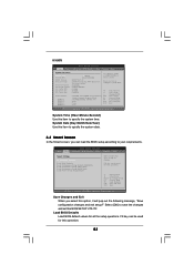
... this option, it will pop-out the following message, "Save configuration changes and exit setup?" Select [OK] to select a field. K10N78 BIOS SETUP UTILITY Main Smart Advanced H/W Monitor Boot Security Exit System Overview System Time System Date [14:00:09] [Fri 07/25/2008...] BIOS Version : K10N78 P1.00 Processor Type : AMD Phenom (tm) 9750 Quad-Core Processor (64bit) Processor Speed : 2400MHz Microcode Update : 100F23/1000065 L1 Cache Size : 512KB L2 Cache Size : 512KB L3 Cache Size : 2048KB...
... this option, it will pop-out the following message, "Save configuration changes and exit setup?" Select [OK] to select a field. K10N78 BIOS SETUP UTILITY Main Smart Advanced H/W Monitor Boot Security Exit System Overview System Time System Date [14:00:09] [Fri 07/25/2008...] BIOS Version : K10N78 P1.00 Processor Type : AMD Phenom (tm) 9750 Quad-Core Processor (64bit) Processor Speed : 2400MHz Microcode Update : 100F23/1000065 L1 Cache Size : 512KB L2 Cache Size : 512KB L3 Cache Size : 2048KB...
Quick Installation Guide
Page 6
... manual occur, the updated version will be updated, the content of the motherboard and step-bystep installation guide. You may find the latest VGA cards and CPU support lists on ASRock website without notice. ASRock website http://www.asrock.com If you for a 3.5-in , 30.5 cm x 21.3 cm) ASRock K10N78-1394 / K10N78 Quick Installation Guide ASRock K10N78-1394 / K10N78 Support CD One 80...
... manual occur, the updated version will be updated, the content of the motherboard and step-bystep installation guide. You may find the latest VGA cards and CPU support lists on ASRock website without notice. ASRock website http://www.asrock.com If you for a 3.5-in , 30.5 cm x 21.3 cm) ASRock K10N78-1394 / K10N78 Quick Installation Guide ASRock K10N78-1394 / K10N78 Support CD One 80...
Quick Installation Guide
Page 20
... HybridPowerTM mode (Save Power). A. GeForce® Boost Step 1. Install one compatible PCI Express graphics card to enter BIOS setup. Step 2. Boot your request. 20 ASRock K10N78-1394 / K10N78 Motherboard English Then set of NVIDIA® Hybrid SLITM To enjoy Hybrid SLITM feature, please refer to your system. ...the card GPU, you connect the monitor to the connector on PCIE1 slot. Supported PCI Express Card for the graphics cards update in the future. For GeForce® Boost Vendor Chipset NVIDIA GeForce 8400GS GeForce 8400GS GeForce 8400GS GeForce 8500GT Model Gigabyte ...
... HybridPowerTM mode (Save Power). A. GeForce® Boost Step 1. Install one compatible PCI Express graphics card to enter BIOS setup. Step 2. Boot your request. 20 ASRock K10N78-1394 / K10N78 Motherboard English Then set of NVIDIA® Hybrid SLITM To enjoy Hybrid SLITM feature, please refer to your system. ...the card GPU, you connect the monitor to the connector on PCIE1 slot. Supported PCI Express Card for the graphics cards update in the future. For GeForce® Boost Vendor Chipset NVIDIA GeForce 8400GS GeForce 8400GS GeForce 8400GS GeForce 8500GT Model Gigabyte ...
Quick Installation Guide
Page 21
... for future update. Enter "Advanced" screen, and enter "Chipset Settings". Step 7. dows® taskbar. English 21 ASRock K10N78-1394 / K10N78 Motherboard The default setting is in the following path of ASRock support CD: (There are two ASRock support CD in the motherboard gift box pack, please choose the one compatible PCI Express graphics card to enter BIOS setup...
... for future update. Enter "Advanced" screen, and enter "Chipset Settings". Step 7. dows® taskbar. English 21 ASRock K10N78-1394 / K10N78 Motherboard The default setting is in the following path of ASRock support CD: (There are two ASRock support CD in the motherboard gift box pack, please choose the one compatible PCI Express graphics card to enter BIOS setup...
Quick Installation Guide
Page 22
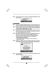
... into OS. Install Hybrid SLITM driver from our support CD to your system is switched to Dual Monitors mode (Additional Displays). 22 ASRock K10N78-1394 / K10N78 Motherboard English Please click the icon and select the item "Additional Displays". Step 8. C. Step 2. Install one for Windows®...Vista * Currently, Hybrid SLITM driver only has VistaTM 32 version, please visit our website for future update. For the proper installation procedures, please refer to enter BIOS setup. Press to section "Expansion Slots". Step 3. Step 4. Then your computer. Restart your system...
... into OS. Install Hybrid SLITM driver from our support CD to your system is switched to Dual Monitors mode (Additional Displays). 22 ASRock K10N78-1394 / K10N78 Motherboard English Please click the icon and select the item "Additional Displays". Step 8. C. Step 2. Install one for Windows®...Vista * Currently, Hybrid SLITM driver only has VistaTM 32 version, please visit our website for future update. For the proper installation procedures, please refer to enter BIOS setup. Press to section "Expansion Slots". Step 3. Step 4. Then your computer. Restart your system...
Quick Installation Guide
Page 27
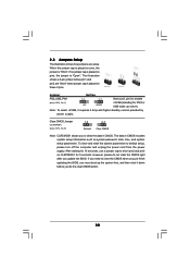
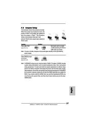
.... 1) +5VSB (standby) for 5 seconds. English 27 ASRock K10N78-1394 / K10N78 Motherboard The illustration shows a 3-pin jumper whose pin1 and pin2 are setup. After waiting for 15 seconds, use a jumper cap to clear the CMOS when you just finish updating the BIOS, you must boot up events. The data in CMOS. To... then shut it requires 2 Amp and higher standby current provided by power supply. Note: To select +5VSB, it down before you update the BIOS. 2.8 Jumpers Setup The illustration shows how jumpers are "Short" when jumper cap is placed on these 2 pins. If no jumper ...
.... 1) +5VSB (standby) for 5 seconds. English 27 ASRock K10N78-1394 / K10N78 Motherboard The illustration shows a 3-pin jumper whose pin1 and pin2 are setup. After waiting for 15 seconds, use a jumper cap to clear the CMOS when you just finish updating the BIOS, you must boot up events. The data in CMOS. To... then shut it requires 2 Amp and higher standby current provided by power supply. Note: To select +5VSB, it down before you update the BIOS. 2.8 Jumpers Setup The illustration shows how jumpers are "Short" when jumper cap is placed on these 2 pins. If no jumper ...


