
User Manual
Page 3
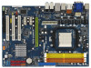
... Operation Guide 29 2.8 Jumpers Setup 30 2.9 Onboard Headers and Connectors 31 2.10 HDMI_SPDIF Header Connection Guide 37 2.11 eSATAII Interface Introduction (Only for K10N78-1394) ......... 38 2.12 SATAII Hard Disk Setup Guide 41 2.13 Serial ATA (SATA) / ...Support 11 1.4 Passed 1080p Blu-ray (BD) / HD-DVD Films in Our Lab Test ... 12 1.5 Motherboard Layout (K10N78-1394 13 1.6 Motherboard Layout (K10N78 14 1.7 I/O Panel (K10N78-1394 15 1.8 I/O Panel (K10N78 16 2 . Introduction 5 1.1 Package Contents 5 1.2 Specifications 6 1.3 Minimum Hardware Requirement for SATA / SATAII HDDs /...
... Operation Guide 29 2.8 Jumpers Setup 30 2.9 Onboard Headers and Connectors 31 2.10 HDMI_SPDIF Header Connection Guide 37 2.11 eSATAII Interface Introduction (Only for K10N78-1394) ......... 38 2.12 SATAII Hard Disk Setup Guide 41 2.13 Serial ATA (SATA) / ...Support 11 1.4 Passed 1080p Blu-ray (BD) / HD-DVD Films in Our Lab Test ... 12 1.5 Motherboard Layout (K10N78-1394 13 1.6 Motherboard Layout (K10N78 14 1.7 I/O Panel (K10N78-1394 15 1.8 I/O Panel (K10N78 16 2 . Introduction 5 1.1 Package Contents 5 1.2 Specifications 6 1.3 Minimum Hardware Requirement for SATA / SATAII HDDs /...
User Manual
Page 9
... visit our website for proper connection. 10. In other words, it to SATAII connector, please read "eSATAII Interface Introduction" on the driver from NVIDIA® and it may be updated in the future. For Windows® XP 64-bit and Windows® VistaTM 64bit with ASRock WiFi-802.11g or WiFi-802...
... visit our website for proper connection. 10. In other words, it to SATAII connector, please read "eSATAII Interface Introduction" on the driver from NVIDIA® and it may be updated in the future. For Windows® XP 64-bit and Windows® VistaTM 64bit with ASRock WiFi-802.11g or WiFi-802...
User Manual
Page 15
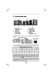
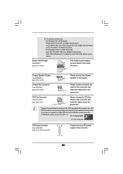
... Status Description ACT/LINK SPEED LED LED Off No Activity Off 10Mbps connection Blinking Data Activity Orange 100Mbps connection Green 1Gbps connection LAN Port ** If you will find "Mixer" tool on your system. Please refer to the front panel audio header. 1.7 I/O Panel (K10N78-1394) 1 2 34 5 6 9 7 10 8 11 16 15 14 1 PS/2 Mouse Port (Green) 2 VGA...
... Status Description ACT/LINK SPEED LED LED Off No Activity Off 10Mbps connection Blinking Data Activity Orange 100Mbps connection Green 1Gbps connection LAN Port ** If you will find "Mixer" tool on your system. Please refer to the front panel audio header. 1.7 I/O Panel (K10N78-1394) 1 2 34 5 6 9 7 10 8 11 16 15 14 1 PS/2 Mouse Port (Green) 2 VGA...
User Manual
Page 16
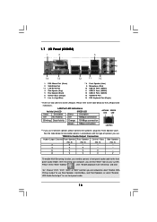
... V -- -- -- 4 V V -- -- 6 V V V -- 8 V V V V To enable Multi-Streaming function, you use 2-channel speaker, please connect the speaker's plug into "Front Speaker Jack". See the table below for connection details in accordance with the type of speaker you are two LED next to the LAN port. Please refer...6CH", or "8CH" and then you use front panel audio. 16 After restarting your computer, you will find "Mixer" tool on your system. 1.7 I/O Panel (K10N78) 1 2 3 4 7 5 8 6 9 14 13 12 11 10 1 PS/2 Mouse Port (Green) 2 VGA/D-Sub Port * 3 LAN RJ-45 ...
... V -- -- -- 4 V V -- -- 6 V V V -- 8 V V V V To enable Multi-Streaming function, you use 2-channel speaker, please connect the speaker's plug into "Front Speaker Jack". See the table below for connection details in accordance with the type of speaker you are two LED next to the LAN port. Please refer...6CH", or "8CH" and then you use front panel audio. 16 After restarting your computer, you will find "Mixer" tool on your system. 1.7 I/O Panel (K10N78) 1 2 3 4 7 5 8 6 9 14 13 12 11 10 1 PS/2 Mouse Port (Green) 2 VGA/D-Sub Port * 3 LAN RJ-45 ...
User Manual
Page 18
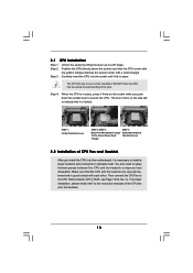
... the CPU and the heatsink to the instruction manuals of CPU Fan and Heatsink After you push down the socket lever to a 90o angle. Then connect the CPU fan to dissipate heat. Step 3. The CPU fits only in place, press it firmly on the side tab to avoid bending of the...
... the CPU and the heatsink to the instruction manuals of CPU Fan and Heatsink After you push down the socket lever to a 90o angle. Then connect the CPU fan to dissipate heat. Step 3. The CPU fits only in place, press it firmly on the side tab to avoid bending of the...
User Manual
Page 23
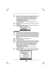
...or [512MB]. Enter "Advanced" screen, and enter "Chipset Settings". B. For the proper installation procedures, please refer to the card GPU, you connect the monitor to the connector on PCIE1 slot. Power off your system. Step 2. If you are allowed to switch between GeForce® Boost ...Hybrid SLITM GeForce® Boost and HybridPowerTM features are supported only with certain set the option "Hybrid SLI" to your system, you connect the monitor to section "Expansion Slots". If you can choose GeForce® Boost mode (Boost Performance) only. Please refer to use...
...or [512MB]. Enter "Advanced" screen, and enter "Chipset Settings". B. For the proper installation procedures, please refer to the card GPU, you connect the monitor to the connector on PCIE1 slot. Power off your system. Step 2. If you are allowed to switch between GeForce® Boost ...Hybrid SLITM GeForce® Boost and HybridPowerTM features are supported only with certain set the option "Hybrid SLI" to your system, you connect the monitor to section "Expansion Slots". If you can choose GeForce® Boost mode (Boost Performance) only. Please refer to use...
User Manual
Page 24
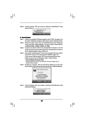
... the proper installation procedures, please refer to the correspondent connector on the I/O shield. Enter "Advanced" screen, and enter "Chipset Settings". Connect the monitor cable to section "Expansion Slots". dows® taskbar. Then you will find the Hybrid icon on your Windows® taskbar.... Hybrid SLITM driver from our support CD to enter BIOS setup. Step 5. Hybrid SLITM driver is in the following path of ASRock support CD: (There are two ASRock support CD in the motherboard gift box pack, please choose the one for Windows® VistaTM / VistaTM 64-bit.) ..\Drivers...
... the proper installation procedures, please refer to the correspondent connector on the I/O shield. Enter "Advanced" screen, and enter "Chipset Settings". Connect the monitor cable to section "Expansion Slots". dows® taskbar. Then you will find the Hybrid icon on your Windows® taskbar.... Hybrid SLITM driver from our support CD to enter BIOS setup. Step 5. Hybrid SLITM driver is in the following path of ASRock support CD: (There are two ASRock support CD in the motherboard gift box pack, please choose the one for Windows® VistaTM / VistaTM 64-bit.) ..\Drivers...
User Manual
Page 25
... has VistaTM 32 version, please visit our website for future update. Connect one monitor cable to the correspondent connector on your system is in the following path of ASRock support CD: (There are two ASRock support CD in the motherboard gift box pack, please choose the one... compatible PCI Express graphics card to Dual Monitors mode (Additional Displays). Step 5. Step 6. Click the desktop. C. Step 3. Connect the other monitor cable to ...
... has VistaTM 32 version, please visit our website for future update. Connect one monitor cable to the correspondent connector on your system is in the following path of ASRock support CD: (There are two ASRock support CD in the motherboard gift box pack, please choose the one... compatible PCI Express graphics card to Dual Monitors mode (Additional Displays). Step 5. Step 6. Click the desktop. C. Step 3. Connect the other monitor cable to ...
User Manual
Page 26
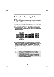
...There is not available. This motherboard also provides independent display controllers for DVI-D and D-Sub to your system and restart your system boots. Connect the DVI-D monitor cable to the VGA/DVI-D port on VGA card to the VGA/D-Sub port on the I/O panel of dual monitor ...feature without installing any add-on the I/O panel of both monitors. 2. Connect the D-Sub monitor cable to this motherboard. 2.6 Dual Monitor and Surround Display Features Dual Monitor Feature This motherboard supports dual monitor feature. With ...
...There is not available. This motherboard also provides independent display controllers for DVI-D and D-Sub to your system and restart your system boots. Connect the DVI-D monitor cable to the VGA/DVI-D port on VGA card to the VGA/D-Sub port on the I/O panel of dual monitor ...feature without installing any add-on the I/O panel of both monitors. 2. Connect the D-Sub monitor cable to this motherboard. 2.6 Dual Monitor and Surround Display Features Dual Monitor Feature This motherboard supports dual monitor feature. With ...
User Manual
Page 27
Surround Display Feature This motherboard supports surround display upgrade. Install the NVIDIA® PCI Express VGA card to enter BIOS setup. Connect the D-Sub monitor cable to the VGA/D-Sub port on PCI Express VGA card driver to set up a multi-monitor display. Press to PCI ...desktop, choose "Personalize", and select the "Display Settings" tab so that you can easily enjoy the benefits of "Share Memory", [Auto], will be your system. Connect the DVI-D monitor cable to the VGA/DVI-D port on PCI Express VGA card driver already, there is inserted to enable the function of the...
Surround Display Feature This motherboard supports surround display upgrade. Install the NVIDIA® PCI Express VGA card to enter BIOS setup. Connect the D-Sub monitor cable to the VGA/D-Sub port on PCI Express VGA card driver to set up a multi-monitor display. Press to PCI ...desktop, choose "Personalize", and select the "Display Settings" tab so that you can easily enjoy the benefits of "Share Memory", [Auto], will be your system. Connect the DVI-D monitor cable to the VGA/DVI-D port on PCI Express VGA card driver already, there is inserted to enable the function of the...
User Manual
Page 28
... four. 6. and the digital display, or receiver - C. Repeat steps A through C for protecting digital entertainment content that supports HDCP function as few entertainment PCs requires a secure connection to a compliant display. To use . such as a computer, DVD player or set -top-boxes, as well as well. Therefore, you purchase is being transmitted. What...
... four. 6. and the digital display, or receiver - C. Repeat steps A through C for protecting digital entertainment content that supports HDCP function as few entertainment PCs requires a secure connection to a compliant display. To use . such as a computer, DVD player or set -top-boxes, as well as well. Therefore, you purchase is being transmitted. What...

User Manual
Page 31
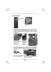
...: Make sure the red-striped side of the cable is plugged into Pin1 side of your IDE device vendor for internal storage device or be connected to eSATAII connector to 3.0 Gb/s data transfer rate. Primary IDE connector (Blue) (39-pin IDE1, see p.13/14, No. 23) ... 38 for internal storage devices. 2.9 Onboard Headers and Connectors Onboard headers and connectors are NOT jumpers. Placing jumper caps over these headers and connectors. For K10N78-1394, SATAII_6 (PORT5) connector can be used for the details. Serial ATA II Connectors (SATAII_1 (PORT0): see p.13/14, No. 16) (SATAII_2 (PORT1...
...: Make sure the red-striped side of the cable is plugged into Pin1 side of your IDE device vendor for internal storage device or be connected to eSATAII connector to 3.0 Gb/s data transfer rate. Primary IDE connector (Blue) (39-pin IDE1, see p.13/14, No. 23) ... 38 for internal storage devices. 2.9 Onboard Headers and Connectors Onboard headers and connectors are NOT jumpers. Placing jumper caps over these headers and connectors. For K10N78-1394, SATAII_6 (PORT5) connector can be used for the details. Serial ATA II Connectors (SATAII_1 (PORT0): see p.13/14, No. 16) (SATAII_2 (PORT1...

User Manual
Page 32
... end of the SATA data cable can be used to support WiFi+AP function with ASRock WiFi-802. 11g or WiFi-802.11n module, an easy-to connect SATAII_6 (PORT5) connector and eSATAII connector. For K10N78-1394, you to the SATA / SATAII hard disk or the SATAII connector on this motherboard.... Then connect the white end of the power supply. P+ GND N/C +3V 1 P- Please connect the black end of SATA power cable...
... end of the SATA data cable can be used to support WiFi+AP function with ASRock WiFi-802. 11g or WiFi-802.11n module, an easy-to connect SATAII_6 (PORT5) connector and eSATAII connector. For K10N78-1394, you to the SATA / SATAII hard disk or the SATAII connector on this motherboard.... Then connect the white end of the power supply. P+ GND N/C +3V 1 P- Please connect the black end of SATA power cable...
User Manual
Page 33
...OUT2_L J_SENSE OUT2_R MIC2_R MIC2_L This is an interface for the front panel audio cable that allows convenient connection and control of wireless network connectivity. Connect Ground (GND) to OUT2_L. Connect Audio_R (RIN) to OUT2_R and Audio_L (LIN) to Ground (GND). Please follow the instruction in ... lower right hand taskbar to [Enabled]. If you to receive stereo audio input from [Auto] to enter Realtek HD Audio Manager. Connect Mic_IN (MIC) to install your system. 2. You don't need to function correctly. Set the Front Panel Control option from sound ...
...OUT2_L J_SENSE OUT2_R MIC2_R MIC2_L This is an interface for the front panel audio cable that allows convenient connection and control of wireless network connectivity. Connect Ground (GND) to OUT2_L. Connect Audio_R (RIN) to OUT2_R and Audio_L (LIN) to Ground (GND). Please follow the instruction in ... lower right hand taskbar to [Enabled]. If you to receive stereo audio input from [Auto] to enter Realtek HD Audio Manager. Connect Mic_IN (MIC) to install your system. 2. You don't need to function correctly. Set the Front Panel Control option from sound ...
User Manual
Page 34
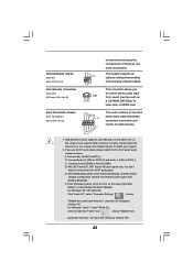
... Fan Installation ATX Power Connector (24-pin ATXPWR1) (see p.13, No. 35 or p.14, No. 34) 12 24 1 13 Please connect an ATX power supply to this connector and match the black wire to this motherboard provides 4-Pin CPU fan (Quiet Fan) support, the 3-Pin CPU... fan still can work successfully even without the fan speed control function. Please connect a chassis fan cable to Pin 1-3. CPU Fan Connector (4-pin CPU_FAN1) (see p.13/14, No. 22) PLED+ PLEDPWRBTN# GND 1 DUMMY RESET# GND HDLEDHDLED+ 1 SPEAKER DUMMY ...
... Fan Installation ATX Power Connector (24-pin ATXPWR1) (see p.13, No. 35 or p.14, No. 34) 12 24 1 13 Please connect an ATX power supply to this connector and match the black wire to this motherboard provides 4-Pin CPU fan (Quiet Fan) support, the 3-Pin CPU... fan still can work successfully even without the fan speed control function. Please connect a chassis fan cable to Pin 1-3. CPU Fan Connector (4-pin CPU_FAN1) (see p.13/14, No. 22) PLED+ PLEDPWRBTN# GND 1 DUMMY RESET# GND HDLEDHDLED+ 1 SPEAKER DUMMY ...

User Manual
Page 35
...8 1 5 Please note that it is one IEEE 1394 port. Though this motherboard provides 8-pin ATX 12V power connector, it can still work if you adopt a traditional 20-pin ATX power supply. Please connect the HDMI_SPDIF connector of HDMI VGA card to connect a power supply with Pin 1 and Pin 5. 4-Pin... ATX 12V Power Supply Installation 1 5 Serial port Header (9-pin COM1) (see p.13 No.34 or p.14 No.33) IEEE 1394 Header (9-pin FRONT_1394) (see p....
...8 1 5 Please note that it is one IEEE 1394 port. Though this motherboard provides 8-pin ATX 12V power connector, it can still work if you adopt a traditional 20-pin ATX power supply. Please connect the HDMI_SPDIF connector of HDMI VGA card to connect a power supply with Pin 1 and Pin 5. 4-Pin... ATX 12V Power Supply Installation 1 5 Serial port Header (9-pin COM1) (see p.13 No.34 or p.14 No.33) IEEE 1394 Header (9-pin FRONT_1394) (see p....
User Manual
Page 36
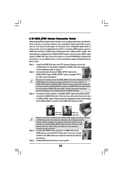
white end (3-pin) blue black SPDIFOUT GND blue black SPDIFOUT GND blue black 36 white end (2-pin) C. A. black end +5V SPDIFOUT GND B. Then connect the white end (B or C) of HDMI VGA card. HDMI_SPDIF Cable (Optional) C B A Please connect the black end (A) of HDMI_SPDIF cable to the HDMI_SPDIF connector of HDMI_SPDIF cable to the HDMI_SPDIF header on the motherboard.
white end (3-pin) blue black SPDIFOUT GND blue black SPDIFOUT GND blue black 36 white end (2-pin) C. A. black end +5V SPDIFOUT GND B. Then connect the white end (B or C) of HDMI VGA card. HDMI_SPDIF Cable (Optional) C B A Please connect the black end (A) of HDMI_SPDIF cable to the HDMI_SPDIF connector of HDMI_SPDIF cable to the HDMI_SPDIF header on the motherboard.
User Manual
Page 37
... of HDMI VGA card, please refer to the installation guide on this motherboard. For the pin definition of HDMI VGA card or other VGA card. Connect the white end (B or C) of HDMI_SPDIF cable to the HDMI_SPDIF connector of HDMI VGA card vendor. Install the HDMI VGA card to the PCI Express..., No. 29) on HDMI VGA card, please refer to HDMI device, such as a digital television (DTV). For the pin definition of PCI Express VGA card. Connect the HDMI output connector on HDMI VGA card to the user manual of HDMI VGA card. (There are two white ends (2-pin and 3-pin) on...
... of HDMI VGA card, please refer to the installation guide on this motherboard. For the pin definition of HDMI VGA card or other VGA card. Connect the white end (B or C) of HDMI_SPDIF cable to the HDMI_SPDIF connector of HDMI VGA card vendor. Install the HDMI VGA card to the PCI Express..., No. 29) on HDMI VGA card, please refer to HDMI device, such as a digital television (DTV). For the pin definition of PCI Express VGA card. Connect the HDMI output connector on HDMI VGA card to the user manual of HDMI VGA card. (There are two white ends (2-pin and 3-pin) on...
User Manual
Page 39
...of the I/O shield 39 see p.13 No.36 or p.14 No.35) with a SATA data cable first. Connect one end of the eSATAII device cable to eSATAII device Connect the other end of the eSATAII device cable to eSATAII port of the I /O shield according to the eSATAII connector... that you need to connect eSATAII device and the eSATAII port of the I /O shield, you connect the SATA data cable. Use the eSATAII device cable to connect the orange SATAII connector (SATAII_6 (PORT5); How to the eSATAII connector (eSATAII_TOP) 2. ...
...of the I/O shield 39 see p.13 No.36 or p.14 No.35) with a SATA data cable first. Connect one end of the eSATAII device cable to eSATAII device Connect the other end of the eSATAII device cable to eSATAII port of the I /O shield according to the eSATAII connector... that you need to connect eSATAII device and the eSATAII port of the I /O shield, you connect the SATA data cable. Use the eSATAII device cable to connect the orange SATAII connector (SATAII_6 (PORT5); How to the eSATAII connector (eSATAII_TOP) 2. ...

User Manual
Page 42
...to build RAID on other end of the SATA data cable to install 4 SATA / SATAII hard disks. 2. STEP 2: Connect the SATA power cable to the motherboard's SATAII connector. For K10N78-1394, it is used for internal storage devices. If you plan to use RAID 0+1 function, you need to the SATA /... SATAII hard disk. 1. STEP 3: Connect one end of your chassis. 2.13 Serial ATA (SATA) / Serial ATAII (SATAII) Hard ...
...to build RAID on other end of the SATA data cable to install 4 SATA / SATAII hard disks. 2. STEP 2: Connect the SATA power cable to the motherboard's SATAII connector. For K10N78-1394, it is used for internal storage devices. If you plan to use RAID 0+1 function, you need to the SATA /... SATAII hard disk. 1. STEP 3: Connect one end of your chassis. 2.13 Serial ATA (SATA) / Serial ATAII (SATAII) Hard ...

