User Manual
Page 5
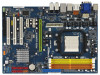
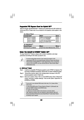
.../index.asp 1.1 Package Contents ASRock K10N78-1394 / K10N78 Motherboard (ATX Form Factor: 12.0-in x 8.4-in, 30.5 cm x 21.3 cm) ASRock K10N78-1394 / K10N78 Quick Installation Guide ASRock K10N78-1394 / K10N78 Support CD One 80-conductor Ultra ATA 66/100/133 IDE Ribbon Cable One Ribbon Cable for purchasing ASRock K10N78-1394 / K10N78 motherboard, a reliable motherboard produced under ASRock's consistently stringent quality control. ASRock website http://www.asrock.com If you for...
.../index.asp 1.1 Package Contents ASRock K10N78-1394 / K10N78 Motherboard (ATX Form Factor: 12.0-in x 8.4-in, 30.5 cm x 21.3 cm) ASRock K10N78-1394 / K10N78 Quick Installation Guide ASRock K10N78-1394 / K10N78 Support CD One 80-conductor Ultra ATA 66/100/133 IDE Ribbon Cable One Ribbon Cable for purchasing ASRock K10N78-1394 / K10N78 motherboard, a reliable motherboard produced under ASRock's consistently stringent quality control. ASRock website http://www.asrock.com If you for...
User Manual
Page 15
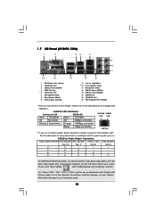
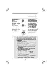
1.7 I/O Panel (K10N78-1394) 1 2 34 5 6 9 7 10 8 11 16 15 14 1 PS/2 Mouse Port (Green) 2 VGA/D-Sub Port 3 USB 2.0 Ports (USB45) 4 IEEE 1394 Port * 5 LAN RJ-45 Port 6 Side Speaker (Gray) 7 Rear Speaker (Black) 8 Central / Bass (Orange) 13 12 9 ** 10 11 12 13 14 15 16... and click "ok". After restarting your system. Choose "2CH", "4CH", "6CH", or "8CH" and then you need to connect a front panel audio cable to the LAN port. TABLE for the LAN port LED indications. LAN Port LED Indications Activity/Link LED SPEED LED Status Description Status Description ACT...
1.7 I/O Panel (K10N78-1394) 1 2 34 5 6 9 7 10 8 11 16 15 14 1 PS/2 Mouse Port (Green) 2 VGA/D-Sub Port 3 USB 2.0 Ports (USB45) 4 IEEE 1394 Port * 5 LAN RJ-45 Port 6 Side Speaker (Gray) 7 Rear Speaker (Black) 8 Central / Bass (Orange) 13 12 9 ** 10 11 12 13 14 15 16... and click "ok". After restarting your system. Choose "2CH", "4CH", "6CH", or "8CH" and then you need to connect a front panel audio cable to the LAN port. TABLE for the LAN port LED indications. LAN Port LED Indications Activity/Link LED SPEED LED Status Description Status Description ACT...
User Manual
Page 16
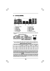
...to the LAN port. Choose "2CH", "4CH", "6CH", or "8CH" and then you need to connect a front panel audio cable to the front panel audio header. LAN Port LED Indications Activity/Link LED SPEED LED Status Description Status Description ACT/LINK SPEED LED LED...". Please refer to the table below for the LAN port LED indications. Please select "Mixer ToolBox" , click "Enable playback multi-streaming", and click "ok". 1.7 I/O Panel (K10N78) 1 2 3 4 7 5 8 6 9 14 13 12 11 10 1 PS/2 Mouse Port (Green) 2 VGA/D-Sub Port * 3 LAN RJ-45 Port 4 Side Speaker (Gray) 5 Rear ...
...to the LAN port. Choose "2CH", "4CH", "6CH", or "8CH" and then you need to connect a front panel audio cable to the front panel audio header. LAN Port LED Indications Activity/Link LED SPEED LED Status Description Status Description ACT/LINK SPEED LED LED...". Please refer to the table below for the LAN port LED indications. Please select "Mixer ToolBox" , click "Enable playback multi-streaming", and click "ok". 1.7 I/O Panel (K10N78) 1 2 3 4 7 5 8 6 9 14 13 12 11 10 1 PS/2 Mouse Port (Green) 2 VGA/D-Sub Port * 3 LAN RJ-45 Port 4 Side Speaker (Gray) 5 Rear ...
User Manual
Page 23
..."Primary Graphics Display" to the connector on PCIE1 slot. If you can choose GeForce® Boost mode (Boost Performance) only. Switch your monitor cable to [Onboard], and save your system. If you connect the monitor to the card GPU, you are supported only with certain set the option... "Hybrid SLI" to the correspondent connector on the PCI Express graphics card on the I/O shield. Connect the monitor cable to [256MB] or [512MB]. Boot your system. After reboot your system, you can switch between GeForce® Boost mode (Boost Performance) and ...
..."Primary Graphics Display" to the connector on PCIE1 slot. If you can choose GeForce® Boost mode (Boost Performance) only. Switch your monitor cable to [Onboard], and save your system. If you connect the monitor to the card GPU, you are supported only with certain set the option... "Hybrid SLI" to the correspondent connector on the PCI Express graphics card on the I/O shield. Connect the monitor cable to [256MB] or [512MB]. Boot your system. After reboot your system, you can switch between GeForce® Boost mode (Boost Performance) and ...
User Manual
Page 24
...computer. Step 6. Restart your system. dows® taskbar. Hybrid SLITM driver is in the following path of ASRock support CD: (There are two ASRock support CD in the motherboard gift box pack, please choose the one compatible PCI Express graphics card to the correspondent...website for future update. B. Step 2. Power off your system. Boot into OS. Boot into OS. Boot your system. Connect the monitor cable to PCIE1 slot (green). Hybrid SLITM driver is GeForce® Boost mode (Boost Performance). For the proper installation procedures, please refer to...
...computer. Step 6. Restart your system. dows® taskbar. Hybrid SLITM driver is in the following path of ASRock support CD: (There are two ASRock support CD in the motherboard gift box pack, please choose the one compatible PCI Express graphics card to the correspondent...website for future update. B. Step 2. Power off your system. Boot into OS. Boot into OS. Boot your system. Connect the monitor cable to PCIE1 slot (green). Hybrid SLITM driver is GeForce® Boost mode (Boost Performance). For the proper installation procedures, please refer to...
User Manual
Page 25
... setup. Click the desktop. Click the desktop. Step 2. Hybrid SLITM driver is in the following path of ASRock support CD: (There are two ASRock support CD in the motherboard gift box pack, please choose the one compatible PCI Express graphics card to the ...future update. Press to your Win- Then set the option "Share Memory" to section "Expansion Slots". Step 4. Additional Displays 25 Connect one monitor cable to HybridPowerTM mode (Save Power). Dual Monitors Step 1. Boot your computer. Step 3. Restart your system. C. Step 8. For the proper installation ...
... setup. Click the desktop. Click the desktop. Step 2. Hybrid SLITM driver is in the following path of ASRock support CD: (There are two ASRock support CD in the motherboard gift box pack, please choose the one compatible PCI Express graphics card to the ...future update. Press to your Win- Then set the option "Share Memory" to section "Expansion Slots". Step 4. Additional Displays 25 Connect one monitor cable to HybridPowerTM mode (Save Power). Dual Monitors Step 1. Boot your computer. Step 3. Restart your system. C. Step 8. For the proper installation ...
User Manual
Page 26
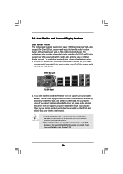
Connect the D-Sub monitor cable to the VGA/D-Sub port on the I /O panel of this motherboard. 1. Then you can easily enjoy the benefits of dual monitor feature without installing any ... one of the two monitors instead of dual monitor function provided by VGA/DVI-D and VGA/D-Sub ports with this motherboard. Connect the DVI-D monitor cable to the VGA/DVI-D port on VGA card to support dual VGA output so that DVI-D and D-sub can freely enjoy the benefits of both...
Connect the D-Sub monitor cable to the VGA/D-Sub port on the I /O panel of this motherboard. 1. Then you can easily enjoy the benefits of dual monitor feature without installing any ... one of the two monitors instead of dual monitor function provided by VGA/DVI-D and VGA/D-Sub ports with this motherboard. Connect the DVI-D monitor cable to the VGA/DVI-D port on VGA card to support dual VGA output so that DVI-D and D-sub can freely enjoy the benefits of both...
User Manual
Page 27
... on the I /O panel of this motherboard. Surround Display Feature This motherboard supports surround display upgrade. Connect the D-Sub monitor cable to this monitor". Boot your system. Press to page 21 for proper expansion card installation procedures for the second monitor. If you...following steps to enable the function of "Share Memory", [Auto], will be your card, one , two, three and four. Connect the DVI-D monitor cable to the steps below . Set up a surround display environment: 1. F. Enter "Share Memory" option to adjust the memory capability to [32MB], [...
... on the I /O panel of this motherboard. Surround Display Feature This motherboard supports surround display upgrade. Connect the D-Sub monitor cable to this monitor". Boot your system. Press to page 21 for proper expansion card installation procedures for the second monitor. If you...following steps to enable the function of "Share Memory", [Auto], will be your card, one , two, three and four. Connect the DVI-D monitor cable to the steps below . Set up a surround display environment: 1. F. Enter "Share Memory" option to adjust the memory capability to [32MB], [...
User Manual
Page 28
... of content as a monitor, television or projector. To use . HDCP stands for protecting digital entertainment content that supports HDCP function as DVD players, satellite and cable HDTV set -top box - such as it is highly recommended that the HDTV or LCD monitor you need to adopt the monitor that uses the...
... of content as a monitor, television or projector. To use . HDCP stands for protecting digital entertainment content that supports HDCP function as DVD players, satellite and cable HDTV set -top box - such as it is highly recommended that the HDTV or LCD monitor you need to adopt the monitor that uses the...

User Manual
Page 31
For K10N78-1394, SATAII_6 (PORT5) connector can be used for internal storage ...of the connector. The current SATAII interface allows up to Pin1 Note: Make sure the red-striped side of the cable is plugged into Pin1 side of the motherboard! • Floppy Connector (33-pin FLOPPY1) (see p.13/14, ... (PORT2) SATAII_5 (PORT4) SATAII_2 (PORT1) SATAII_4 (PORT3) SATAII_6 (PORT5) These six Serial ATAII (SATAII) connectors support SATA data cables for details about eSATAII and eSATAII installation procedures. 31 Serial ATA II Connectors (SATAII_1 (PORT0): see p.13/14, No. 16) ...
For K10N78-1394, SATAII_6 (PORT5) connector can be used for internal storage ...of the connector. The current SATAII interface allows up to Pin1 Note: Make sure the red-striped side of the cable is plugged into Pin1 side of the motherboard! • Floppy Connector (33-pin FLOPPY1) (see p.13/14, ... (PORT2) SATAII_5 (PORT4) SATAII_2 (PORT1) SATAII_4 (PORT3) SATAII_6 (PORT5) These six Serial ATAII (SATAII) connectors support SATA data cables for details about eSATAII and eSATAII installation procedures. 31 Serial ATA II Connectors (SATAII_1 (PORT0): see p.13/14, No. 16) ...

User Manual
Page 32
...or the SATAII connector on this motherboard. It can be used to support WiFi+AP function with ASRock WiFi-802. 11g or WiFi-802.11n module, an easy-to-use the SATA data cable to create a wireless Each USB 2.0 header can be connected to support 2 USB 2.0 ports....) connect to the SATA HDD power connector connect to the power connector of SATA power cable to 3.0 Gb/s data transfer rate. P+ GND N/C +5V 32 This eSATAII connector supports SATA data cable for external SATAII function. For K10N78-1394, you to connect SATAII_6 (PORT5) connector and eSATAII connector. P+ GND N/C +3V 1 ...
...or the SATAII connector on this motherboard. It can be used to support WiFi+AP function with ASRock WiFi-802. 11g or WiFi-802.11n module, an easy-to-use the SATA data cable to create a wireless Each USB 2.0 header can be connected to support 2 USB 2.0 ports....) connect to the SATA HDD power connector connect to the power connector of SATA power cable to 3.0 Gb/s data transfer rate. P+ GND N/C +5V 32 This eSATAII connector supports SATA data cable for external SATAII function. For K10N78-1394, you to connect SATAII_6 (PORT5) connector and eSATAII connector. P+ GND N/C +3V 1 ...
User Manual
Page 33
... CD1) (CD1: see p.13/14, No. 26) GND PRESENCE# MIC_RET OUT_RET 1 OUT2_L J_SENSE OUT2_R MIC2_R MIC2_L This is an interface for the front panel audio cable that allows convenient connection and control of wireless network connectivity. Front Panel Audio Header (9-pin HD_AUDIO1) (see p.13/14, No. 25) IRTX +5V DUMMY 1 GND...
... CD1) (CD1: see p.13/14, No. 26) GND PRESENCE# MIC_RET OUT_RET 1 OUT2_L J_SENSE OUT2_R MIC2_R MIC2_L This is an interface for the front panel audio cable that allows convenient connection and control of wireless network connectivity. Front Panel Audio Header (9-pin HD_AUDIO1) (see p.13/14, No. 25) IRTX +5V DUMMY 1 GND...
User Manual
Page 34
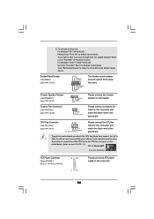
G. Please connect a chassis fan cable to this motherboard, please connect it to the ground pin. If you want to the ground pin. For Windows® VistaTM / VistaTM 64-bit OS: ... device. Pin 1-3 Connected 3-Pin Fan Installation ATX Power Connector (24-pin ATXPWR1) (see p.13/14, No. 3) 4 3 2 1 GND +12V CPU_FAN_SPEED FAN_SPEED_CONTROL Please connect the CPU fan cable to this motherboard provides 4-Pin CPU fan (Quiet Fan) support, the 3-Pin CPU fan still can work successfully even without the fan speed control function...
G. Please connect a chassis fan cable to this motherboard, please connect it to the ground pin. If you want to the ground pin. For Windows® VistaTM / VistaTM 64-bit OS: ... device. Pin 1-3 Connected 3-Pin Fan Installation ATX Power Connector (24-pin ATXPWR1) (see p.13/14, No. 3) 4 3 2 1 GND +12V CPU_FAN_SPEED FAN_SPEED_CONTROL Please connect the CPU fan cable to this motherboard provides 4-Pin CPU fan (Quiet Fan) support, the 3-Pin CPU fan still can work successfully even without the fan speed control function...
User Manual
Page 36
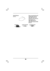
Then connect the white end (B or C) of HDMI VGA card. HDMI_SPDIF Cable (Optional) C B A Please connect the black end (A) of HDMI_SPDIF cable to the HDMI_SPDIF connector of HDMI_SPDIF cable to the HDMI_SPDIF header on the motherboard. white end (3-pin) blue black SPDIFOUT GND blue black SPDIFOUT GND blue black 36 black end +5V SPDIFOUT GND B. white end (2-pin) C. A.
Then connect the white end (B or C) of HDMI VGA card. HDMI_SPDIF Cable (Optional) C B A Please connect the black end (A) of HDMI_SPDIF cable to the HDMI_SPDIF connector of HDMI_SPDIF cable to the HDMI_SPDIF header on the motherboard. white end (3-pin) blue black SPDIFOUT GND blue black SPDIFOUT GND blue black 36 black end +5V SPDIFOUT GND B. white end (2-pin) C. A.
User Manual
Page 37
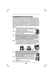
...end (B or C) of PCI Express VGA card. Please do not connect the white end of HDMI_SPDIF cable to the fan connector of HDMI_SPDIF cable to the PCI Express Graphics slot on HDMI_SPDIF cable. Otherwise, the motherboard and the VGA card may cause permanent damage to this motherboard. 2.10 HDMI_SPDIF ... audio output to HDMI VGA card, allows the system to connect HDMI Digital TV/projector/ LCD devices. Connect the black end (A) of HDMI_SPDIF cable to the user manual of HDMI_SPDIF connectors on HDMI VGA card, please refer to the HDMI_SPDIF header (HDMI_SPDIF1, yellow, see page 13/14, No...
...end (B or C) of PCI Express VGA card. Please do not connect the white end of HDMI_SPDIF cable to the fan connector of HDMI_SPDIF cable to the PCI Express Graphics slot on HDMI_SPDIF cable. Otherwise, the motherboard and the VGA card may cause permanent damage to this motherboard. 2.10 HDMI_SPDIF ... audio output to HDMI VGA card, allows the system to connect HDMI Digital TV/projector/ LCD devices. Connect the black end (A) of HDMI_SPDIF cable to the user manual of HDMI_SPDIF connectors on HDMI VGA card, please refer to the HDMI_SPDIF header (HDMI_SPDIF1, yellow, see page 13/14, No...
User Manual
Page 39
see p.13/14 No.11) and the eSATAII connector (eSATAII_TOP; Connect one end of the eSATAII device cable to eSATAII device Connect the other end of the eSATAII device cable to eSATAII port of the I /O shield according to the eSATAII connector that you need to connect the orange SATAII connector (SATAII_6 (... eSATAII? see p.13 No.36 or p.14 No.35) with a SATA data cable first. In order to connect eSATAII device and the eSATAII port of the I/O shield, you connect the SATA data cable. Use the eSATAII device cable to enable the eSATAII port of the I /O shield 39 How to the eSATAII...
see p.13/14 No.11) and the eSATAII connector (eSATAII_TOP; Connect one end of the eSATAII device cable to eSATAII device Connect the other end of the eSATAII device cable to eSATAII port of the I /O shield according to the eSATAII connector that you need to connect the orange SATAII connector (SATAII_6 (... eSATAII? see p.13 No.36 or p.14 No.35) with a SATA data cable first. In order to connect eSATAII device and the eSATAII port of the I/O shield, you connect the SATA data cable. Use the eSATAII device cable to enable the eSATAII port of the I /O shield 39 How to the eSATAII...

User Manual
Page 42
...RAID 0+1 function, you to the SATA / SATAII hard disk. STEP 1: Install the SATA / SATAII hard disks into the drive bays of the SATA data cable to install at least 2 SATA / SATAII hard disks. Under IDE mode, SATAII_5 (PORT4) and SATAII_6 (PORT5) cannot function. 42 STEP 4: Connect the ... on other words, if SATAII_6 (PORT5) is recommended to install 4 SATA / SATAII hard disks. 2. STEP 3: Connect one end of the SATA data cable to install 3 SATA / SATAII hard disks. For K10N78-1394, it is used for eSATAII port, please build RAID on this motherboard for internal storage devices.
...RAID 0+1 function, you to the SATA / SATAII hard disk. STEP 1: Install the SATA / SATAII hard disks into the drive bays of the SATA data cable to install at least 2 SATA / SATAII hard disks. Under IDE mode, SATAII_5 (PORT4) and SATAII_6 (PORT5) cannot function. 42 STEP 4: Connect the ... on other words, if SATAII_6 (PORT5) is recommended to install 4 SATA / SATAII hard disks. 2. STEP 3: Connect one end of the SATA data cable to install 3 SATA / SATAII hard disks. For K10N78-1394, it is used for eSATAII port, please build RAID on this motherboard for internal storage devices.
User Manual
Page 44
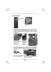
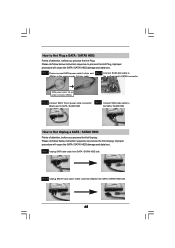
...power connector and IDE 1x4-pin conventional power connector interfaces, the IDE 1x4-pin conventional power connector interface is available on our website: www.asrock.com 2. Please make sure the SATA / SATAII driver is indicated in RAID / AHCI mode. Points of our motherboard is installed into... 1. Before you process the Hot Plug: 1. Please follow below operation guide of HDD crash or data loss. 44 SATA data cable (Red) B. SATA power cable SATA 7-pin connector The SATA 15-pin power connector (Black) connect to SATA / SATAII HDD 1x4-pin conventional power connector (White...
...power connector and IDE 1x4-pin conventional power connector interfaces, the IDE 1x4-pin conventional power connector interface is available on our website: www.asrock.com 2. Please make sure the SATA / SATAII driver is indicated in RAID / AHCI mode. Points of our motherboard is installed into... 1. Before you process the Hot Plug: 1. Please follow below operation guide of HDD crash or data loss. 44 SATA data cable (Red) B. SATA power cable SATA 7-pin connector The SATA 15-pin power connector (Black) connect to SATA / SATAII HDD 1x4-pin conventional power connector (White...
User Manual
Page 45
... SATA / SATAII HDD side. 45 Step 2 Unplug SATA 15-pin power cable connector (Black) from SATA / SATAII HDD side. Step 4 Connect SATA data cable to process the Hot Unplug, improper procedure will cause the SATA / SATAII HDD damage and data loss. the motherboard's SATAII connector. How ...you process the Hot Plug: Please do follow below instruction sequence to the SATA / SATAII HDD. SATA power cable 1x4-pin power connector (White) Step 3 Connect SATA 15-pin power cable connector (Black) end to process the Hot Plug, improper procedure will cause the SATA / SATAII HDD damage and...
... SATA / SATAII HDD side. 45 Step 2 Unplug SATA 15-pin power cable connector (Black) from SATA / SATAII HDD side. Step 4 Connect SATA data cable to process the Hot Unplug, improper procedure will cause the SATA / SATAII HDD damage and data loss. the motherboard's SATAII connector. How ...you process the Hot Plug: Please do follow below instruction sequence to the SATA / SATAII HDD. SATA power cable 1x4-pin power connector (White) Step 3 Connect SATA 15-pin power cable connector (Black) end to process the Hot Plug, improper procedure will cause the SATA / SATAII HDD damage and...

Quick Installation Guide
Page 4
...-- 6 V V V -- 8 V V V V To enable Multi-Streaming function, you need to connect a front panel audio cable to the table below for the LAN port LED indications. Please select "Mixer ToolBox" , click "Enable playback multi-streaming", and click "ok". I/O Panel (K10N78-1394) 1 PS/2 Mouse Port (Green) 2 VGA/D-Sub Port 3 USB 2.0 Ports (USB45) 4 IEEE... and Front Speaker, or select "Realtek HDA Audio 2nd output" to use front panel audio. 4 ASRock K10N78-1394 / K10N78 Motherboard English See the table below for connection details in accordance with the type of speaker you use...
...-- 6 V V V -- 8 V V V V To enable Multi-Streaming function, you need to connect a front panel audio cable to the table below for the LAN port LED indications. Please select "Mixer ToolBox" , click "Enable playback multi-streaming", and click "ok". I/O Panel (K10N78-1394) 1 PS/2 Mouse Port (Green) 2 VGA/D-Sub Port 3 USB 2.0 Ports (USB45) 4 IEEE... and Front Speaker, or select "Realtek HDA Audio 2nd output" to use front panel audio. 4 ASRock K10N78-1394 / K10N78 Motherboard English See the table below for connection details in accordance with the type of speaker you use...
