
English Manual
Page 1
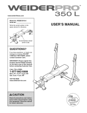
... equipment. www.weiderfitness.com Model No. Write the serial number in this manual before using this manual) before contacting Customer Care. Serial Number Decal (under seat) QUESTIONS? Keep this manual for reference. MT Sat. 8 a.m.-4 p.m. please contact Customer Care. WEBE15910.0 Serial No.
... equipment. www.weiderfitness.com Model No. Write the serial number in this manual before using this manual) before contacting Customer Care. Serial Number Decal (under seat) QUESTIONS? Keep this manual for reference. MT Sat. 8 a.m.-4 p.m. please contact Customer Care. WEBE15910.0 Serial No.
English Manual
Page 4
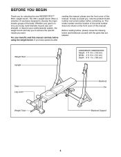
...cm) Width: 3 ft. 9 in. (114 cm) Depth: 6 ft. 1 in. (185 cm) Seat Leg Lever Backrest Pin Weight Tube Backrest Support 4 The 350 L weight bench offers a selection of exercises designed to achieve the specific results you , note the product model number and serial ...number before using the weight bench. BEFORE YOU BEGIN Thank you to develop the major muscle groups of the body. To help you for selecting the new WEIDER PRO™ 350 L weight bench...
...cm) Width: 3 ft. 9 in. (114 cm) Depth: 6 ft. 1 in. (185 cm) Seat Leg Lever Backrest Pin Weight Tube Backrest Support 4 The 350 L weight bench offers a selection of exercises designed to achieve the specific results you , note the product model number and serial ...number before using the weight bench. BEFORE YOU BEGIN Thank you to develop the major muscle groups of the body. To help you for selecting the new WEIDER PRO™ 350 L weight bench...
English Manual
Page 8
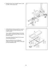
Insert the Short Axle through the Backrest Support. Attach the Backrest (16) to the Main Frame (7) with four M6 x 40mm Screws (34) and four M6 Washers (44). 44 9 4 34 3 44 44 34 34 8 44 Welded Tubes 34 8 6. Identify Backrest Frames A and B (8, 9) and ori- 7 ent them so that the welded tubes are in the locations shown. 16 Then, identify the Backrest Support (4) and the Short Axle (3). Attach the Seat (15) to the Backrest Frames (8, 9) with four M6 x 16mm Screws (33). 6 15 7 33 33 7. Next, press a Backrest Frame (8, 9) onto each end of the Short Axle (3).
Insert the Short Axle through the Backrest Support. Attach the Backrest (16) to the Main Frame (7) with four M6 x 40mm Screws (34) and four M6 Washers (44). 44 9 4 34 3 44 44 34 34 8 44 Welded Tubes 34 8 6. Identify Backrest Frames A and B (8, 9) and ori- 7 ent them so that the welded tubes are in the locations shown. 16 Then, identify the Backrest Support (4) and the Short Axle (3). Attach the Seat (15) to the Backrest Frames (8, 9) with four M6 x 16mm Screws (33). 6 15 7 33 33 7. Next, press a Backrest Frame (8, 9) onto each end of the Short Axle (3).
English Manual
Page 14
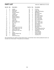
... 6 1 Folding Lever 7 1 Main Frame 8 1 Backrest Frame A 9 1 Backrest Frame B 10 1 Front Leg 11 1 Leg Lever 12 1 Weight Tube 13 1 M16 x 240mm Bolt 14 3 Pad Tube 15 1 Seat 16 1 Backrest 17 1 Spring 18 4 25mm Square Inner Cap 19 3 45mm Square Inner Cap 20 1 Square Outer Cap 21 4 Rectangular Outer Cap 22 1 Pin 23...
... 6 1 Folding Lever 7 1 Main Frame 8 1 Backrest Frame A 9 1 Backrest Frame B 10 1 Front Leg 11 1 Leg Lever 12 1 Weight Tube 13 1 M16 x 240mm Bolt 14 3 Pad Tube 15 1 Seat 16 1 Backrest 17 1 Spring 18 4 25mm Square Inner Cap 19 3 45mm Square Inner Cap 20 1 Square Outer Cap 21 4 Rectangular Outer Cap 22 1 Pin 23...

