
Canadian English Manual
Page 1
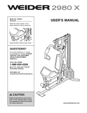
Model No. 30295.0 Serial No. Serial Number Decal (under seat) QUESTIONS? www.weiderfitness.com If you have questions, or if parts are damaged or missing, PLEASE CONTACT OUR CUSTOMER SERVICE DEPARTMENT DIRECTLY. CALL TOLL-FREE: 1-888-936-4266 Mon.-Fri., 8:00 until 17:00 ET (excluding holidays) OR E-MAIL US: [email protected] USERʼS MANUAL CAUTION Read all precautions and instructions in the space above for future reference. Write the serial number in this manual before using this manual for future reference. Keep this equipment.
Model No. 30295.0 Serial No. Serial Number Decal (under seat) QUESTIONS? www.weiderfitness.com If you have questions, or if parts are damaged or missing, PLEASE CONTACT OUR CUSTOMER SERVICE DEPARTMENT DIRECTLY. CALL TOLL-FREE: 1-888-936-4266 Mon.-Fri., 8:00 until 17:00 ET (excluding holidays) OR E-MAIL US: [email protected] USERʼS MANUAL CAUTION Read all precautions and instructions in the space above for future reference. Write the serial number in this manual before using this manual for future reference. Keep this equipment.
Canadian English Manual
Page 2
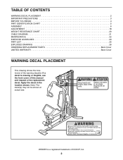
... decal in the location shown. Note: The decal(s) may not be shown at actual size. TABLE OF CONTENTS WARNING DECAL PLACEMENT 2 IMPORTANT PRECAUTIONS 3 BEFORE YOU BEGIN 4 PART IDENTIFICATION CHART 5 ASSEMBLY 6 ADJUSTMENT 18 WEIGHT RESISTANCE CHART 20 CABLE DIAGRAM 21 MAINTENANCE 22 EXERCISE GUIDELINES 23 PART LIST 25 EXPLODED DRAWING 26 ORDERING REPLACEMENT PARTS Back Cover LIMITED WARRANTY Back Cover WARNING DECAL PLACEMENT This drawing shows the location(s) of this manual and request a free replacement decal.
... decal in the location shown. Note: The decal(s) may not be shown at actual size. TABLE OF CONTENTS WARNING DECAL PLACEMENT 2 IMPORTANT PRECAUTIONS 3 BEFORE YOU BEGIN 4 PART IDENTIFICATION CHART 5 ASSEMBLY 6 ADJUSTMENT 18 WEIGHT RESISTANCE CHART 20 CABLE DIAGRAM 21 MAINTENANCE 22 EXERCISE GUIDELINES 23 PART LIST 25 EXPLODED DRAWING 26 ORDERING REPLACEMENT PARTS Back Cover LIMITED WARRANTY Back Cover WARNING DECAL PLACEMENT This drawing shows the location(s) of this manual and request a free replacement decal.
Canadian English Manual
Page 3
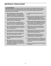
.... tem. Make sure that the cables are raised; Use your weight sys- Always wear athletic shoes for home use of this manual. 3 If you feel faint or if you are adequately informed of all parts regularly. Keep hands and feet away from moving parts. 10. Never release the arms, leg lever, lat bar, or handle strap while weights are on the pulleys. 4. Inspect and properly tighten all precautions. 3.
.... tem. Make sure that the cables are raised; Use your weight sys- Always wear athletic shoes for home use of this manual. 3 If you feel faint or if you are adequately informed of all parts regularly. Keep hands and feet away from moving parts. 10. Never release the arms, leg lever, lat bar, or handle strap while weights are on the pulleys. 4. Inspect and properly tighten all precautions. 3.
Canadian English Manual
Page 4
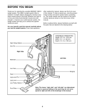
... Pulley Station Arm Pin Right Side Backrest Curl Pad Seat Leg Lever Pin Leg Lever Low Pulley Station Foot Plate ASSEMBLED DIMENSIONS: Height: 6 ft. 4 in. (193 cm) Width: 3 ft. 1 in. (94 cm) Depth: 5 ft. 5 in the manual. 4 BEFORE YOU BEGIN Thank you , note the product model number and serial number before you have questions after reading this manual, please see the front cover of the body. If you use...
... Pulley Station Arm Pin Right Side Backrest Curl Pad Seat Leg Lever Pin Leg Lever Low Pulley Station Foot Plate ASSEMBLED DIMENSIONS: Height: 6 ft. 4 in. (193 cm) Width: 3 ft. 1 in. (94 cm) Depth: 5 ft. 5 in the manual. 4 BEFORE YOU BEGIN Thank you , note the product model number and serial number before you have questions after reading this manual, please see the front cover of the body. If you use...
Canadian English Manual
Page 5
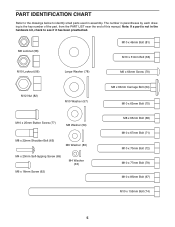
...hardware kit, check to identify small parts used in assembly. Note: If a part is the key number of the part, from the PART LIST near the end of this manual. M8 Locknut (58) M10 x 46mm Bolt (81) M10 x 51mm Bolt (66) M10 Locknut (56) Large Washer (78) M6 x 63mm Screw (70) M12 Nut (82) M10... x 20mm Self-tapping Screw (69) M6 x 16mm Screw (62) M4 Washer (33) M8 x 63mm Carriage Bolt (64) M10 x 63mm Bolt (75) M8 x 65mm Bolt (68) M10 x 67mm Bolt (71) M10 x 70mm Bolt (72) M10 x 77mm Bolt (79) M10 x 85mm Bolt (67) M10 x 155mm Bolt (74) 5 PART IDENTIFICATION CHART Refer to the drawings ...
...hardware kit, check to identify small parts used in assembly. Note: If a part is the key number of the part, from the PART LIST near the end of this manual. M8 Locknut (58) M10 x 46mm Bolt (81) M10 x 51mm Bolt (66) M10 Locknut (56) Large Washer (78) M6 x 63mm Screw (70) M12 Nut (82) M10... x 20mm Self-tapping Screw (69) M6 x 16mm Screw (62) M4 Washer (33) M8 x 63mm Carriage Bolt (64) M10 x 63mm Bolt (75) M8 x 65mm Bolt (68) M10 x 67mm Bolt (71) M10 x 70mm Bolt (72) M10 x 77mm Bolt (79) M10 x 85mm Bolt (67) M10 x 155mm Bolt (74) 5 PART IDENTIFICATION CHART Refer to the drawings ...
Canadian English Manual
Page 6
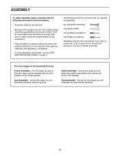
... attach the cables and pulleys that connect the arms to walk around the weight system as you assemble it will begin by assembling the base and the uprights that there is completed. • For help identifying small parts, use the PART IDENTIFICATION CHART on page 5. • The following information and instructions: • Assembly requires two persons. • Because of its weight and size, the weight system should be assembled in the location...
... attach the cables and pulleys that connect the arms to walk around the weight system as you assemble it will begin by assembling the base and the uprights that there is completed. • For help identifying small parts, use the PART IDENTIFICATION CHART on page 5. • The following information and instructions: • Assembly requires two persons. • Because of its weight and size, the weight system should be assembled in the location...
Canadian English Manual
Page 8
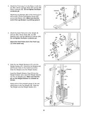
.... Attach the Seat Frame (6) to the Base (1) with the pin holes on the Weight Selector is pointing upward. Apply some of the Leg Bumper is oriented as shown. Attach the Front Leg (7) to the Upright (3) with an M4 x 20mm Self-tapping Screw (69) and an M4 Washer (33). Slide the two Weight Bumpers (27) onto the Weight Guides (21). Do not tighten the...
.... Attach the Seat Frame (6) to the Base (1) with the pin holes on the Weight Selector is pointing upward. Apply some of the Leg Bumper is oriented as shown. Attach the Front Leg (7) to the Upright (3) with an M4 x 20mm Self-tapping Screw (69) and an M4 Washer (33). Slide the two Weight Bumpers (27) onto the Weight Guides (21). Do not tighten the...

Canadian English Manual
Page 9
.... 7 56 8 Welded Support 7 Grease 79 8. Attach the Top Frame (4) between the Weight Guides (21) with the welded support on the bottom. 6 Attach the Top Frame (4) to the Front Leg (7) with two M4 x 20mm Self-tapping Screws (69). Orient the Leg Lever (8) with an M10 x 155mm Bolt (74), two M10 Washers...support on the side shown. Tighten the M8 Nylon Locknuts (58). 59 4 68 59 76 76 56 57 57 74 Welded Support 58 58 3 21 21 Arm Assembly 7. Insert the Arm Pins into the two holes in the Upright (3). 8 56 69 5 40 9 4 Holes 79 3 Grease 69 40 Grease an M10 x 77mm Bolt...
.... 7 56 8 Welded Support 7 Grease 79 8. Attach the Top Frame (4) between the Weight Guides (21) with the welded support on the bottom. 6 Attach the Top Frame (4) to the Front Leg (7) with two M4 x 20mm Self-tapping Screws (69). Orient the Leg Lever (8) with an M10 x 155mm Bolt (74), two M10 Washers...support on the side shown. Tighten the M8 Nylon Locknuts (58). 59 4 68 59 76 76 56 57 57 74 Welded Support 58 58 3 21 21 Arm Assembly 7. Insert the Arm Pins into the two holes in the Upright (3). 8 56 69 5 40 9 4 Holes 79 3 Grease 69 40 Grease an M10 x 77mm Bolt...

Canadian English Manual
Page 10
... 57 Grease 57 10 56 Cable Assembly 11 11. Do not overtighten the Nylon Locknut; See the CABLE DIAGRAM on the Shoulder Bolt. 10 58 39 54 Grease 65 Attach the Cable to the Left Arm (10) with the Shoulder Bolt and an M8 Nylon Locknut (58). Grease an M10 x 85mm Bolt (67) and two Arm Bushings (44). Attach a Cable Pivot (39) to the indicated Cable Pivot...
... 57 Grease 57 10 56 Cable Assembly 11 11. Do not overtighten the Nylon Locknut; See the CABLE DIAGRAM on the Shoulder Bolt. 10 58 39 54 Grease 65 Attach the Cable to the Left Arm (10) with the Shoulder Bolt and an M8 Nylon Locknut (58). Grease an M10 x 85mm Bolt (67) and two Arm Bushings (44). Attach a Cable Pivot (39) to the indicated Cable Pivot...

Canadian English Manual
Page 15
... thread an M12 Nut (82) onto the 27 High Cable (55). 25. Place a Large Washer (78) on top of the Weight Selector (24). Route the High Cable (55) over a 90mm Thin Pulley (47). 25 Attach the Pulley inside the Top Frame with the M10 x 67mm Bolt (71) used in step 23, an 11mm Spacer (49), an M10 Washer (...(57), two 12mm Spacers (52), and an M10 Nylon Locknut (56). 56 57 52 4 48 55 52 57 71 27. Tighten the M12 Nut (82) against the Large Washer (78). 55 82 78 24 15 Tighten the High Cable (55) into the Weight Selector (24) until all the slack is removed from the cables.
... thread an M12 Nut (82) onto the 27 High Cable (55). 25. Place a Large Washer (78) on top of the Weight Selector (24). Route the High Cable (55) over a 90mm Thin Pulley (47). 25 Attach the Pulley inside the Top Frame with the M10 x 67mm Bolt (71) used in step 23, an 11mm Spacer (49), an M10 Washer (...(57), two 12mm Spacers (52), and an M10 Nylon Locknut (56). 56 57 52 4 48 55 52 57 71 27. Tighten the M12 Nut (82) against the Large Washer (78). 55 82 78 24 15 Tighten the High Cable (55) into the Weight Selector (24) until all the slack is removed from the cables.
Canadian English Manual
Page 16
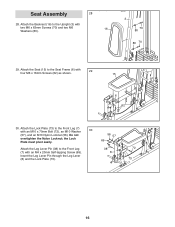
... the Seat Frame (6) with an M4 x 20mm Self-tapping Screw (69). the Lock Plate must pivot easily. Insert the Leg Lever Pin through the Leg Lever (8) and the Lock Plate (73). 56 57 69 38 8 72 73 7 16 Do not overtighten the Nylon Locknut; Attach the Lock Plate (73) to the Upright (3) with an M10 x 70mm Bolt (72...
... the Seat Frame (6) with an M4 x 20mm Self-tapping Screw (69). the Lock Plate must pivot easily. Insert the Leg Lever Pin through the Leg Lever (8) and the Lock Plate (73). 56 57 69 38 8 72 73 7 16 Do not overtighten the Nylon Locknut; Attach the Lock Plate (73) to the Upright (3) with an M10 x 70mm Bolt (72...
Canadian English Manual
Page 17
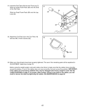
... Screws (62). 32 14 13 62 33. Make sure that the cables move smoothly, find and correct the problem. The use of the remaining parts will need to remove the slack by tightening the cables. Slide two Small Foam Pads (28) onto the ends of the cables does not move smoothly around the pulleys. Slide two Small Foam Pads (28) onto the Leg Lever...
... Screws (62). 32 14 13 62 33. Make sure that the cables move smoothly, find and correct the problem. The use of the remaining parts will need to remove the slack by tightening the cables. Slide two Small Foam Pads (28) onto the ends of the cables does not move smoothly around the pulleys. Slide two Small Foam Pads (28) onto the Leg Lever...
Canadian English Manual
Page 18
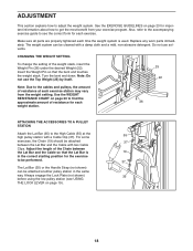
... between the Lat Bar and the Cable with a Cable Clip (37). Insert the Weight Pin so that the Lat Bar is used. Note: Do not use solvents. ADJUSTMENT This section explains how to the cables and pulleys, the amount of resistance at each exercise station may vary from your exercise program. Replace any worn parts immediately. CHANGING THE WEIGHT SETTING To change the setting of resistance for each exercise. ATTACHING THE ACCESSORIES TO A PULLEY STATION Attach the Lat Bar (35) to...
... between the Lat Bar and the Cable with a Cable Clip (37). Insert the Weight Pin so that the Lat Bar is used. Note: Do not use solvents. ADJUSTMENT This section explains how to the cables and pulleys, the amount of resistance at each exercise station may vary from your exercise program. Replace any worn parts immediately. CHANGING THE WEIGHT SETTING To change the setting of resistance for each exercise. ATTACHING THE ACCESSORIES TO A PULLEY STATION Attach the Lat Bar (35) to...
Canadian English Manual
Page 19
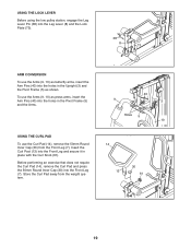
... Front Leg (7). Before performing an exercise that does not require the Curl Pad (14), remove the Curl Pad and press the 50mm Round Inner Cap (30) into the Front Leg and secure it in the Upright (3) and the Pivot Frame (5) as shown. USING THE LOCK LEVER Before using the low pulley station, engage the Leg Lever Pin (38) into the Leg Lever...
... Front Leg (7). Before performing an exercise that does not require the Curl Pad (14), remove the Curl Pad and press the 50mm Round Inner Cap (30) into the Front Leg and secure it in the Upright (3) and the Pivot Frame (5) as shown. USING THE LOCK LEVER Before using the low pulley station, engage the Leg Lever Pin (38) into the Leg Lever...
Canadian English Manual
Page 20
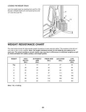
... 173 LEG LEVER (lbs.) 27 57 85 111 159 182 214 LOW PULLEY (lbs.) 26 55 86 119 148 163 187 20 LOCKING THE WEIGHT STACK Lock the weight stack by inserting the Lock Pin (18) through a Weight Guide (21) and securing the Lock (17) onto the Lock Pin. 21 17 18 WEIGHT RESISTANCE CHART The chart below shows the approximate weight resistance at...
... 173 LEG LEVER (lbs.) 27 57 85 111 159 182 214 LOW PULLEY (lbs.) 26 55 86 119 148 163 187 20 LOCKING THE WEIGHT STACK Lock the weight stack by inserting the Lock Pin (18) through a Weight Guide (21) and securing the Lock (17) onto the Lock Pin. 21 17 18 WEIGHT RESISTANCE CHART The chart below shows the approximate weight resistance at...

Canadian English Manual
Page 21
... cm) 4 5 3 2 1 4 2 5 Arm Cable (54) 1 Length: 7 ft. 5 in. (226 cm) 3 6 6 4 3 5 2 1 Low Cable (53) Length: 10 ft. 8 in each drawing show the proper route of the cables. Use the diagram to make sure that the cables, cable traps, pulleys, and guards are not assembled correctly, the weight system will not function properly and damage may occur. The numbers in . (325 cm) 21 CABLE DIAGRAM The diagram below shows...
... cm) 4 5 3 2 1 4 2 5 Arm Cable (54) 1 Length: 7 ft. 5 in. (226 cm) 3 6 6 4 3 5 2 1 Low Cable (53) Length: 10 ft. 8 in each drawing show the proper route of the cables. Use the diagram to make sure that the cables, cable traps, pulleys, and guards are not assembled correctly, the weight system will not function properly and damage may occur. The numbers in . (325 cm) 21 CABLE DIAGRAM The diagram below shows...
Canadian English Manual
Page 22
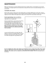
... cover of the weight stack. Reattach the Pulley, Cable Trap, and Half Guards to slip off the weight stack. To tighten the cables, first insert the weight pin into the Weight Selector (24) until the slack is felt, the cables should be tightened. If the cables need to be cleaned with a damp cloth and a mild, non-abrasive detergent. Tighten the Cable into the middle of this manual. 22 Remove...
... cover of the weight stack. Reattach the Pulley, Cable Trap, and Half Guards to slip off the weight stack. To tighten the cables, first insert the weight pin into the Weight Selector (24) until the slack is felt, the cables should be tightened. If the cables need to be cleaned with a damp cloth and a mild, non-abrasive detergent. Tighten the Cable into the middle of this manual. 22 Remove...
Canadian English Manual
Page 23
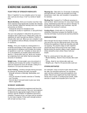
... for exercise. A "set . Adjust the intensity level of an individual exercise as follows: • Change the amount of resistance used , and the numbers of sets and repetitions completed. Toning-Tone your muscles by working them to your muscles and helps to prevent post-exercise problems. EXERCISE FORM Move through the full range of motion for each exercise you want to complete. Select exercises for each workout, and the numbers...
... for exercise. A "set . Adjust the intensity level of an individual exercise as follows: • Change the amount of resistance used , and the numbers of sets and repetitions completed. Toning-Tone your muscles by working them to your muscles and helps to prevent post-exercise problems. EXERCISE FORM Move through the full range of motion for each exercise you want to complete. Select exercises for each workout, and the numbers...
Canadian English Manual
Page 25
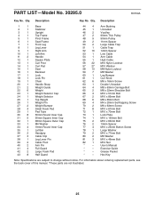
... back cover of this manual. *These parts are subject to change without notice. Grease Packet * - Description Key No. Exercise Guide * - Hex Key Note: Specifications are not illustrated. 25 Description 1 1 Base 2 1 Stabilizer 3 1 Upright 4 1 Top Frame 5 1 Pivot Frame 6 1 Seat Frame 7 1 Front Leg 8 1 Leg Lever 9 1 Right Arm 10 1 Left Arm 11 2 Handle 12 1 Square Plate 13 1 Curl Post 14 1 Curl Pad 15 1 Seat 16 1 Backrest 17 1 Lock 18 1 Lock Pin 19...
... back cover of this manual. *These parts are subject to change without notice. Grease Packet * - Description Key No. Exercise Guide * - Hex Key Note: Specifications are not illustrated. 25 Description 1 1 Base 2 1 Stabilizer 3 1 Upright 4 1 Top Frame 5 1 Pivot Frame 6 1 Seat Frame 7 1 Front Leg 8 1 Leg Lever 9 1 Right Arm 10 1 Left Arm 11 2 Handle 12 1 Square Plate 13 1 Curl Post 14 1 Curl Pad 15 1 Seat 16 1 Backrest 17 1 Lock 18 1 Lock Pin 19...
Canadian English Manual
Page 28
...; All repairs for ninety (90) days from the date of purchase. The warranty extended hereunder is authorized by an ICON authorized service center; Accordingly, the above is in workmanship and material, under this manual. ICON of whatsoever nature. ORDERING REPLACEMENT PARTS To order replacement parts, please see the PART LIST and the EXPLODED DRAWING near the end of this manual) LIMITED WARRANTY ICON of removal or installation; ICONʼ...
...; All repairs for ninety (90) days from the date of purchase. The warranty extended hereunder is authorized by an ICON authorized service center; Accordingly, the above is in workmanship and material, under this manual. ICON of whatsoever nature. ORDERING REPLACEMENT PARTS To order replacement parts, please see the PART LIST and the EXPLODED DRAWING near the end of this manual) LIMITED WARRANTY ICON of removal or installation; ICONʼ...


