
Canadian English Manual
Page 1
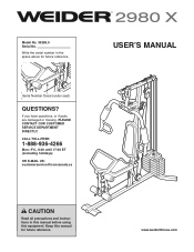
www.weiderfitness.com Keep this equipment. Write the serial number in this manual before using this manual for future reference. CALL TOLL-FREE: 1-888-936-4266 Mon.-Fri., 8:00 until 17:00 ET (excluding holidays) OR E-MAIL US: [email protected] USERʼS MANUAL CAUTION Read all precautions and instructions in the space above for future reference. If you have questions, or if parts are damaged or missing, PLEASE CONTACT OUR CUSTOMER SERVICE DEPARTMENT DIRECTLY. Serial Number Decal (under seat) QUESTIONS? Model No. 30295.0 Serial No.
www.weiderfitness.com Keep this equipment. Write the serial number in this manual before using this manual for future reference. CALL TOLL-FREE: 1-888-936-4266 Mon.-Fri., 8:00 until 17:00 ET (excluding holidays) OR E-MAIL US: [email protected] USERʼS MANUAL CAUTION Read all precautions and instructions in the space above for future reference. If you have questions, or if parts are damaged or missing, PLEASE CONTACT OUR CUSTOMER SERVICE DEPARTMENT DIRECTLY. Serial Number Decal (under seat) QUESTIONS? Model No. 30295.0 Serial No.
Canadian English Manual
Page 2
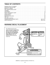
... 25 EXPLODED DRAWING 26 ORDERING REPLACEMENT PARTS Back Cover LIMITED WARRANTY Back Cover WARNING DECAL PLACEMENT This drawing shows the location(s) of ICON IP, Inc. 2 WEIDER is missing or illegible, see the front cover of this manual and request a free replacement decal. Apply the decal in the location shown. If a decal...
... 25 EXPLODED DRAWING 26 ORDERING REPLACEMENT PARTS Back Cover LIMITED WARRANTY Back Cover WARNING DECAL PLACEMENT This drawing shows the location(s) of ICON IP, Inc. 2 WEIDER is missing or illegible, see the front cover of this manual and request a free replacement decal. Apply the decal in the location shown. If a decal...
Canadian English Manual
Page 3
ICON assumes no responsibility for persons over the age of 35 or persons with pre-existing health problems. 2. Always wear athletic shoes for home use of the weight system (see LOCKING THE WEIGHT STACK on your weight system only as described in this product. 1. If you feel faint or if you are exercising, stop immediately and cool down. 16. Before beginning any worn parts immediately. 6. If the cables bind while you experience pain while exercising, stop immediately and make sure that the cables are on the pulleys at all parts regularly. the weights will ...
ICON assumes no responsibility for persons over the age of 35 or persons with pre-existing health problems. 2. Always wear athletic shoes for home use of the weight system (see LOCKING THE WEIGHT STACK on your weight system only as described in this product. 1. If you feel faint or if you are exercising, stop immediately and cool down. 16. Before beginning any worn parts immediately. 6. If the cables bind while you experience pain while exercising, stop immediately and make sure that the cables are on the pulleys at all parts regularly. the weights will ...
Canadian English Manual
Page 4
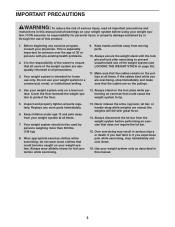
For your benefit, read this manual carefully before contacting us assist you for selecting the versatile WEIDER® 2980 X weight system. they do not correspond to right and left side" are determined relative to achieve the specific results you want. If you use the ... , note the product model number and serial number before you have questions after reading this manual, please see the front cover of this manual. The 2980 X weight system offers a selection of weight stations designed to tone your body, build dramatic muscle size and strength, or improve your goal is to develop...
For your benefit, read this manual carefully before contacting us assist you for selecting the versatile WEIDER® 2980 X weight system. they do not correspond to right and left side" are determined relative to achieve the specific results you want. If you use the ... , note the product model number and serial number before you have questions after reading this manual, please see the front cover of this manual. The 2980 X weight system offers a selection of weight stations designed to tone your body, build dramatic muscle size and strength, or improve your goal is to develop...
Canadian English Manual
Page 5
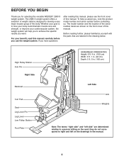
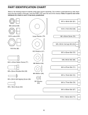
PART IDENTIFICATION CHART Refer to the drawings below to see if it has been preattached. Note: If a part is not in the hardware kit, check to identify small parts used in parentheses by each drawing is the key number of the part, from the PART LIST near the end of this manual. M8 Locknut (58) M10 x 46mm Bolt (81) M10 x 51mm Bolt (66) M10 Locknut (56) Large Washer (78) M6 x 63mm Screw (70) M12 Nut (82) M10 Washer (57) M10 x 25mm Button Screw (77) M8 Washer (59) M8 x 22mm Shoulder Bolt (65) M6 Washer (80) M4 x 20mm Self-tapping Screw (69) M6 x 16mm Screw (62) M4 Washer (33) ...
PART IDENTIFICATION CHART Refer to the drawings below to see if it has been preattached. Note: If a part is not in the hardware kit, check to identify small parts used in parentheses by each drawing is the key number of the part, from the PART LIST near the end of this manual. M8 Locknut (58) M10 x 46mm Bolt (81) M10 x 51mm Bolt (66) M10 Locknut (56) Large Washer (78) M6 x 63mm Screw (70) M12 Nut (82) M10 Washer (57) M10 x 25mm Button Screw (77) M8 Washer (59) M8 x 22mm Shoulder Bolt (65) M6 Washer (80) M4 x 20mm Self-tapping Screw (69) M6 x 16mm Screw (62) M4 Washer (33) ...
Canadian English Manual
Page 6
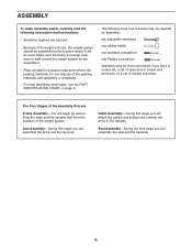
ASSEMBLY To make assembly easier, carefully read the following tools (not included) may be required for assembly: two adjustable wrenches one rubber mallet one standard screwdriver one Phillips screwdriver Assembly may be used. Make sure that there is completed. • For help identifying small parts, use the PART IDENTIFICATION CHART on page 5. • The following information and instructions: • Assembly requires two persons. • Because of the weight system. Cable Assembly-During this stage you will begin by assembling the base and the uprights that connect the ...
ASSEMBLY To make assembly easier, carefully read the following tools (not included) may be required for assembly: two adjustable wrenches one rubber mallet one standard screwdriver one Phillips screwdriver Assembly may be used. Make sure that there is completed. • For help identifying small parts, use the PART IDENTIFICATION CHART on page 5. • The following information and instructions: • Assembly requires two persons. • Because of the weight system. Cable Assembly-During this stage you will begin by assembling the base and the uprights that connect the ...
Canadian English Manual
Page 7
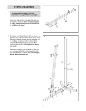
Frame Assembly 1 1. Attach the Upright (3) to the Base (1) with two M10 x 67mm Bolts (71), two M10 Washers (57), and two M10 Nylon Locknuts (56). Insert four M8 x 63mm Carriage Bolts (64) up through the Base (1). Note: It may be helpful to place a piece of tape over the bolt heads to the Base (1) with the two indicated M8 x 63mm Carriage Bolts (64) and two M8 Nylon Locknuts (58). Fully tighten the Nylon Locknuts. Do not tighten the Nylon Locknuts yet. 1 64 64 21 21 Holes 3 58 71 58 71 1 64 57 56 57 2 7 To make assembly easier, read the information on page 6 before you...
Frame Assembly 1 1. Attach the Upright (3) to the Base (1) with two M10 x 67mm Bolts (71), two M10 Washers (57), and two M10 Nylon Locknuts (56). Insert four M8 x 63mm Carriage Bolts (64) up through the Base (1). Note: It may be helpful to place a piece of tape over the bolt heads to the Base (1) with the two indicated M8 x 63mm Carriage Bolts (64) and two M8 Nylon Locknuts (58). Fully tighten the Nylon Locknuts. Do not tighten the Nylon Locknuts yet. 1 64 64 21 21 Holes 3 58 71 58 71 1 64 57 56 57 2 7 To make assembly easier, read the information on page 6 before you...
Canadian English Manual
Page 8
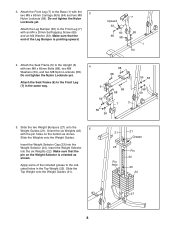
Attach the Leg Bumper (60) to the Front Leg (7) with the pin holes on the Weight Selector is pointing upward. Do not tighten the Nylon Locknuts yet. Orient the six Weights (22) 5 with an M4 x 20mm Self-tapping Screw (69) and an M4 Washer (33). Make sure that the end of the included grease to the Front Leg (7) in the Top Weight (25). Attach the Seat Frame (6) to the Base (1) with two M8 x 65mm Bolts (68), two M8 Washers (59), and two M8 Nylon Locknuts (58). Insert the Weight Selector into the Weight Selector (24). Attach the Seat Frame (6) to the indicated holes in ...
Attach the Leg Bumper (60) to the Front Leg (7) with the pin holes on the Weight Selector is pointing upward. Do not tighten the Nylon Locknuts yet. Orient the six Weights (22) 5 with an M4 x 20mm Self-tapping Screw (69) and an M4 Washer (33). Make sure that the end of the included grease to the Front Leg (7) in the Top Weight (25). Attach the Seat Frame (6) to the Base (1) with two M8 x 65mm Bolts (68), two M8 Washers (59), and two M8 Nylon Locknuts (58). Insert the Weight Selector into the Weight Selector (24). Attach the Seat Frame (6) to the indicated holes in ...

Canadian English Manual
Page 9
the Leg Lever must pivot easily. Grease an M10 x 77mm Bolt (79). the Pivot Frame must pivot easily. 7 56 8 Welded Support 7 Grease 79 8. Attach the two Arm Pins (40) to the Front Leg (7) with two M4 x 20mm Self-tapping Screws (69). Orient the Top Frame (4) with two M8 x 65mm Bolts (68), two M8 Washers (59), and two M8 Nylon Locknuts (58). Grease an M10 x 77mm Bolt (79). Do not overtighten the Nylon Locknut; See steps 2-4, and 6. Attach the Leg Lever to the Pivot Frame (5) with the Bolt and an M10 Nylon Locknut (56). Attach the Pivot Frame (5) to the Upright (3)...
the Leg Lever must pivot easily. Grease an M10 x 77mm Bolt (79). the Pivot Frame must pivot easily. 7 56 8 Welded Support 7 Grease 79 8. Attach the two Arm Pins (40) to the Front Leg (7) with two M4 x 20mm Self-tapping Screws (69). Orient the Top Frame (4) with two M8 x 65mm Bolts (68), two M8 Washers (59), and two M8 Nylon Locknuts (58). Grease an M10 x 77mm Bolt (79). Do not overtighten the Nylon Locknut; See steps 2-4, and 6. Attach the Leg Lever to the Pivot Frame (5) with the Bolt and an M10 Nylon Locknut (56). Attach the Pivot Frame (5) to the Upright (3)...

Canadian English Manual
Page 10
the Cable Pivot must pivot easily. Assemble the Right Arm (9) in the same way. 9 66 Grease 39 56 10 11 42 57 77 57 Grease 9 44 67 5 44 57 Grease 57 10 56 Cable Assembly 11 11. Do not overtighten the Nylon Locknut; Grease an M8 x 22mm Shoulder Bolt (65). Identify the Arm Cable (54). Attach a Cable Pivot (39) to the indicated Cable Pivot (39) with the 9 Bolt and an M10 Nylon Locknut (56). Slide the Large Foam Pad onto the Left Arm (10). Attach the Cable to the Left Arm (10) with the Shoulder Bolt and an M8 Nylon Locknut (58). Grease an M10 x 85mm...
the Cable Pivot must pivot easily. Assemble the Right Arm (9) in the same way. 9 66 Grease 39 56 10 11 42 57 77 57 Grease 9 44 67 5 44 57 Grease 57 10 56 Cable Assembly 11 11. Do not overtighten the Nylon Locknut; Grease an M8 x 22mm Shoulder Bolt (65). Identify the Arm Cable (54). Attach a Cable Pivot (39) to the indicated Cable Pivot (39) with the 9 Bolt and an M10 Nylon Locknut (56). Slide the Large Foam Pad onto the Left Arm (10). Attach the Cable to the Left Arm (10) with the Shoulder Bolt and an M8 Nylon Locknut (58). Grease an M10 x 85mm...

Canadian English Manual
Page 11
Route the Arm Cable (54) under a 90mm Pulley (48). Make sure that the Cable Trap is oriented to the Double U-bracket (63) with an M10 x 63mm Bolt (75) and an M10 Nylon Locknut (56). 12. Attach the Pulley and two Half Guards (43) 13 to hold the Cable in the groove of the U-bracket as shown. 54 48 43 81 56 43 63 14. Make sure that the Cable Trap is oriented to the Upright (3) with an M10 x 63mm Bolt (75) and an M10 Nylon Locknut (56). Make sure that the Half Guards are on the outside of the V-pulley. 75 41 50 57 46 41 54 3 56 11 Attach the V-pulley, a Large...
Route the Arm Cable (54) under a 90mm Pulley (48). Make sure that the Cable Trap is oriented to the Double U-bracket (63) with an M10 x 63mm Bolt (75) and an M10 Nylon Locknut (56). 12. Attach the Pulley and two Half Guards (43) 13 to hold the Cable in the groove of the U-bracket as shown. 54 48 43 81 56 43 63 14. Make sure that the Cable Trap is oriented to the Upright (3) with an M10 x 63mm Bolt (75) and an M10 Nylon Locknut (56). Make sure that the Half Guards are on the outside of the V-pulley. 75 41 50 57 46 41 54 3 56 11 Attach the V-pulley, a Large...

Canadian English Manual
Page 12
Attach the Arm Cable (54) to the indicated 15 Cable Pivot (39) with an M10 x 67mm Bolt (71), two M10 Washers (57), two 12mm Spacers (52), and an M10 Nylon Locknut (56). 8 52 56 57 53 48 7 52 57 71 17. Grease 54 39 58 65 16. Route the Cable 16 through the Leg Lever (8) and the Front Leg (7). Make sure that the cable end can pivot easily on the Shoulder Bolt. Attach a 90mm Pulley (48) inside the Leg Lever (8), over the Low Cable (53), with an M10 x 17 67mm Bolt (71), two M10 Washers (57), two 12mm Spacers (52), and an M10 Nylon Locknut (56). 56 52 57 48 7 53 57 52 71 ...
Attach the Arm Cable (54) to the indicated 15 Cable Pivot (39) with an M10 x 67mm Bolt (71), two M10 Washers (57), two 12mm Spacers (52), and an M10 Nylon Locknut (56). 8 52 56 57 53 48 7 52 57 71 17. Grease 54 39 58 65 16. Route the Cable 16 through the Leg Lever (8) and the Front Leg (7). Make sure that the cable end can pivot easily on the Shoulder Bolt. Attach a 90mm Pulley (48) inside the Leg Lever (8), over the Low Cable (53), with an M10 x 17 67mm Bolt (71), two M10 Washers (57), two 12mm Spacers (52), and an M10 Nylon Locknut (56). 56 52 57 48 7 53 57 52 71 ...

Canadian English Manual
Page 13
Attach the 18 Pulley inside the Upright with an M10 x 46mm Bolt (81) and an M10 Nylon Locknut (56). Attach the Pulley and two Half Guards (43) 19 to the Base (1) with an M10 x 46mm Bolt (81) and an M10 Nylon Locknut (56). Make sure that the Half Guards are on the outside of the bracket as shown. 56 43 48 63 43 53 81 20. Route the Low Cable (53) over a 90mm Pulley (48). Attach the Pulley and two Half Guards (43) to the Double U-bracket (63) with an M10 x 67mm Bolt (71), two M10 Washers (57), two 12mm Spacers (52), and an M10 Nylon Locknut (56). 56 52 57 48...
Attach the 18 Pulley inside the Upright with an M10 x 46mm Bolt (81) and an M10 Nylon Locknut (56). Attach the Pulley and two Half Guards (43) 19 to the Base (1) with an M10 x 46mm Bolt (81) and an M10 Nylon Locknut (56). Make sure that the Half Guards are on the outside of the bracket as shown. 56 43 48 63 43 53 81 20. Route the Low Cable (53) over a 90mm Pulley (48). Attach the Pulley and two Half Guards (43) to the Double U-bracket (63) with an M10 x 67mm Bolt (71), two M10 Washers (57), two 12mm Spacers (52), and an M10 Nylon Locknut (56). 56 52 57 48...

Canadian English Manual
Page 14
Route the Cable up through the Top Frame 23 (4). Attach the Pulley, a Cable Trap (51), and two Half Guards (43) at the upper hole in the groove of the Pulley and that the Half Guards are showing above the Nylon Locknut. 45 58 59 58 53 45 53 22. bracket (45) with an M8 Washer (59) and an M8 Nylon 21 Locknut (58). Attach the Low Cable (53) to hold the Cable in the U- Identify the High Cable (55). Attach the Pulley inside the Top Frame with an M10 x 67mm Bolt (71), two M10 Washers (57), two 12mm Spacers (52), and an M10 Nylon Locknut (56). 57 56 52 55 4 48 ...
Route the Cable up through the Top Frame 23 (4). Attach the Pulley, a Cable Trap (51), and two Half Guards (43) at the upper hole in the groove of the Pulley and that the Half Guards are showing above the Nylon Locknut. 45 58 59 58 53 45 53 22. bracket (45) with an M8 Washer (59) and an M8 Nylon 21 Locknut (58). Attach the Low Cable (53) to hold the Cable in the U- Identify the High Cable (55). Attach the Pulley inside the Top Frame with an M10 x 67mm Bolt (71), two M10 Washers (57), two 12mm Spacers (52), and an M10 Nylon Locknut (56). 57 56 52 55 4 48 ...

Canadian English Manual
Page 15
Attach the Pulley inside the Top Frame with an M10 x 67mm Bolt (71), two M10 Washers (57), two 12mm Spacers (52), and an M10 Nylon Locknut (56). 56 57 52 4 48 55 52 57 71 27. 25. Route the High Cable (55) over a 90mm Pulley 26 (48) and down through the Top Frame (4) and over a 90mm Thin Pulley (47). 25 Attach the Pulley inside the Top Frame with the M10 x 67mm Bolt (71) used in step 23, an 11mm Spacer (49), an M10 Washer (57), and an M10 Nylon Locknut (56). 55 56 57 49 47 4 71 26. Tighten the High Cable (55) into the Weight Selector (24) until all the slack is removed...
Attach the Pulley inside the Top Frame with an M10 x 67mm Bolt (71), two M10 Washers (57), two 12mm Spacers (52), and an M10 Nylon Locknut (56). 56 57 52 4 48 55 52 57 71 27. 25. Route the High Cable (55) over a 90mm Pulley 26 (48) and down through the Top Frame (4) and over a 90mm Thin Pulley (47). 25 Attach the Pulley inside the Top Frame with the M10 x 67mm Bolt (71) used in step 23, an 11mm Spacer (49), an M10 Washer (57), and an M10 Nylon Locknut (56). 55 56 57 49 47 4 71 26. Tighten the High Cable (55) into the Weight Selector (24) until all the slack is removed...
Canadian English Manual
Page 16
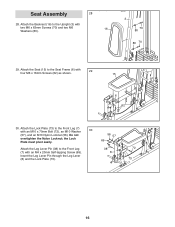
Attach the Seat (15) to the Front Leg (7) with four M6 x 16mm Screws (62) as shown. 29 15 6 62 30. Do not overtighten the Nylon Locknut; the Lock Plate must pivot easily. Attach the Lock Plate (73) to the Seat Frame (6) with an M10 x 70mm Bolt (72), an M10 Washer 30 (57), and an M10 Nylon Locknut (56). Seat Assembly 28 28. Attach the Leg Lever Pin (38) to the Upright (3) with an M4 x 20mm Self-tapping Screw (69). Attach the Backrest (16) to the Front Leg (7) with two M6 x 63mm Screws (70) and two M6 16 Washers (80). 3 70 80 80 70 29. Insert the Leg Lever Pin ...
Attach the Seat (15) to the Front Leg (7) with four M6 x 16mm Screws (62) as shown. 29 15 6 62 30. Do not overtighten the Nylon Locknut; the Lock Plate must pivot easily. Attach the Lock Plate (73) to the Seat Frame (6) with an M10 x 70mm Bolt (72), an M10 Washer 30 (57), and an M10 Nylon Locknut (56). Seat Assembly 28 28. Attach the Leg Lever Pin (38) to the Upright (3) with an M4 x 20mm Self-tapping Screw (69). Attach the Backrest (16) to the Front Leg (7) with two M6 x 63mm Screws (70) and two M6 16 Washers (80). 3 70 80 80 70 29. Insert the Leg Lever Pin ...
Canadian English Manual
Page 17
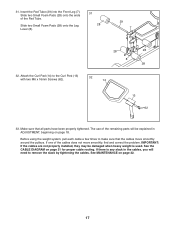
Before using the weight system, pull each cable a few times to remove the slack by tightening the cables. If one of the cables does not move smoothly around the pulleys. Insert the Pad Tube (29) into the Front Leg (7). Make sure that the cables move smoothly, find and correct the problem. The use of the Pad Tube. If there is used. 31. See MAINTENANCE on page 21 for proper cable routing. See the CABLE DIAGRAM on page 22. 17 Attach the Curl Pad (14) to the Curl Post (13) with two M6 x 16mm Screws (62). 32 14 13 62 33. Slide two Small Foam Pads (28) onto the ends...
Before using the weight system, pull each cable a few times to remove the slack by tightening the cables. If one of the cables does not move smoothly around the pulleys. Insert the Pad Tube (29) into the Front Leg (7). Make sure that the cables move smoothly, find and correct the problem. The use of the Pad Tube. If there is used. 31. See MAINTENANCE on page 21 for proper cable routing. See the CABLE DIAGRAM on page 22. 17 Attach the Curl Pad (14) to the Curl Post (13) with two M6 x 16mm Screws (62). 32 14 13 62 33. Slide two Small Foam Pads (28) onto the ends...
Canadian English Manual
Page 18
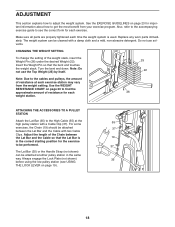
Do not use the Top Weight (25) by itself. 25 22 Note: Due to the cables and pulleys, the amount of the weight stack, insert the Weight Pin (26) under the desired Weight (22). CHANGING THE WEIGHT SETTING To change the setting of resistance at each time the weight system is 19 in the same way. Use the WEIGHT RESISTANCE CHART on page 20 to be performed. 37 The Lat Bar (35) or the Handle Strap (not shown) can be cleaned with a damp cloth and a mild, non-abrasive detergent. Adjust the length of resistance for the exercise to find the approximate amount of the Chain ...
Do not use the Top Weight (25) by itself. 25 22 Note: Due to the cables and pulleys, the amount of the weight stack, insert the Weight Pin (26) under the desired Weight (22). CHANGING THE WEIGHT SETTING To change the setting of resistance at each time the weight system is 19 in the same way. Use the WEIGHT RESISTANCE CHART on page 20 to be performed. 37 The Lat Bar (35) or the Handle Strap (not shown) can be cleaned with a damp cloth and a mild, non-abrasive detergent. Adjust the length of resistance for the exercise to find the approximate amount of the Chain ...
Canadian English Manual
Page 19
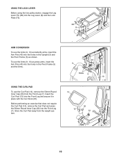
Insert the Curl Post (13) into the Front Leg and secure it in the Pivot Frame (5) and the Arms. USING THE CURL PAD To use the Curl Pad (14), remove the 50mm Round Inner Cap (30) from the weight system. 40 9 3 Holes 5 10 14 30 13 61 7 19 USING THE LOCK LEVER Before using the low pulley station, engage the Leg Lever Pin (38) into the Leg Lever (8) and the Lock Plate (73). 38 8 73 ARM CONVERSION To use the Arms (9, 10) as butterfly arms, insert the Arm Pins (40) into the holes in the Upright (3) and the Pivot Frame (5) as press arms, insert the Arm Pins (40) into the holes in ...
Insert the Curl Post (13) into the Front Leg and secure it in the Pivot Frame (5) and the Arms. USING THE CURL PAD To use the Curl Pad (14), remove the 50mm Round Inner Cap (30) from the weight system. 40 9 3 Holes 5 10 14 30 13 61 7 19 USING THE LOCK LEVER Before using the low pulley station, engage the Leg Lever Pin (38) into the Leg Lever (8) and the Lock Plate (73). 38 8 73 ARM CONVERSION To use the Arms (9, 10) as butterfly arms, insert the Arm Pins (40) into the holes in the Upright (3) and the Pivot Frame (5) as press arms, insert the Arm Pins (40) into the holes in ...
Canadian English Manual
Page 20
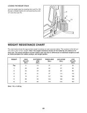
The numbers in individual weights as well as friction between the cables, pulleys, and weight guides. WEIGHT Top 1 2 3 4 5 6 HIGH PULLEY (lbs.) 11 26 42 61 70 86 101 Note: 1 lb. = 0.45 kg BUTTERFLY ARM (lbs.) 16 22 30 41 51 63 82 PRESS ARM (lbs.) 27 44 62 97 127 144 173 LEG LEVER (lbs.) 27 57 85 111 159 182 214 LOW PULLEY (lbs.) 26 55 86 119 148 163 187 20 The actual resistance at each arm. weights. Note: The weight resistance shown for the butterfly arm station is for each exercise station. LOCKING THE WEIGHT STACK Lock the weight stack by inserting the Lock Pin (18) ...
The numbers in individual weights as well as friction between the cables, pulleys, and weight guides. WEIGHT Top 1 2 3 4 5 6 HIGH PULLEY (lbs.) 11 26 42 61 70 86 101 Note: 1 lb. = 0.45 kg BUTTERFLY ARM (lbs.) 16 22 30 41 51 63 82 PRESS ARM (lbs.) 27 44 62 97 127 144 173 LEG LEVER (lbs.) 27 57 85 111 159 182 214 LOW PULLEY (lbs.) 26 55 86 119 148 163 187 20 The actual resistance at each arm. weights. Note: The weight resistance shown for the butterfly arm station is for each exercise station. LOCKING THE WEIGHT STACK Lock the weight stack by inserting the Lock Pin (18) ...
