Service Manual
Page 2
... (w/h/d) (Approx.) 430 × 157.5 × 316 mm (17 × 6 1/4 × 12 1/2 inches) including projecting parts and controls Mass (Approx.) 8.0 kg (17 lb 11 oz) Design and specifications are subject to change the tuning scale. REPLACE THESE COMPONENTS WITH... SONY PARTS WHOSE PART NUMBERS APPEAR AS SHOWN IN THIS MANUAL OR IN SUPPLEMENTS PUBLISHED BY SONY. 2 All preset stations will be erased when you change without notice. To reset the scale to 9 kHz or 10 kHz. STR-K7100 AM tuner... kHz), repeat the procedure. After tuning in any AM station, turn off the receiver.
... (w/h/d) (Approx.) 430 × 157.5 × 316 mm (17 × 6 1/4 × 12 1/2 inches) including projecting parts and controls Mass (Approx.) 8.0 kg (17 lb 11 oz) Design and specifications are subject to change the tuning scale. REPLACE THESE COMPONENTS WITH... SONY PARTS WHOSE PART NUMBERS APPEAR AS SHOWN IN THIS MANUAL OR IN SUPPLEMENTS PUBLISHED BY SONY. 2 All preset stations will be erased when you change without notice. To reset the scale to 9 kHz or 10 kHz. STR-K7100 AM tuner... kHz), repeat the procedure. After tuning in any AM station, turn off the receiver.
Service Manual
Page 3
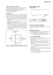
....). A. Using an AC voltmeter to use caution not to ordinary solder. 3 MODEL IDENTIFICATION - Ordinary soldering irons can be measured by any exposed metal part having a return to chassis, must have a 2 V AC range are suitable. (See Fig. Leakage current can be used but unleaded solder may ... It is applied for AC leakage. MODEL US Part No. Nearly all other exposed metal parts for too long, so be careful! • Strong viscosity Unleaded solder is more viscous (sticky, less prone to flow) than ordinary solder. STR-K7100 SAFETY CHECK-OUT (US MODEL) After correcting the...
....). A. Using an AC voltmeter to use caution not to ordinary solder. 3 MODEL IDENTIFICATION - Ordinary soldering irons can be measured by any exposed metal part having a return to chassis, must have a 2 V AC range are suitable. (See Fig. Leakage current can be used but unleaded solder may ... It is applied for AC leakage. MODEL US Part No. Nearly all other exposed metal parts for too long, so be careful! • Strong viscosity Unleaded solder is more viscous (sticky, less prone to flow) than ordinary solder. STR-K7100 SAFETY CHECK-OUT (US MODEL) After correcting the...
Service Manual
Page 4
... - DCAC, Power Key Section - .... 37 5-24. DCDC Section 41 5-30. EXPLODED VIEWS 6-1. GENERAL Description and location of parts 5 2. DISASSEMBLY 2-1. STANDBY Board 11 3. Digital Section 16 5-4. XM Section 19 5-7. Key/Display Section 20 5-8. Video Section 32... - Schematic Diagram - HDMI SW Section 33 5-20. Schematic Diagram - Schematic Diagram - Schematic Diagram - Power Section 40 5-29. STR-K7100 TABLE OF CONTENTS 1. Block Diagram - Output/Power Section 21 5-9. Printed Wiring Boards - Digital Section (1/2 26 5-13. Digital Section ...
... - DCAC, Power Key Section - .... 37 5-24. DCDC Section 41 5-30. EXPLODED VIEWS 6-1. GENERAL Description and location of parts 5 2. DISASSEMBLY 2-1. STANDBY Board 11 3. Digital Section 16 5-4. XM Section 19 5-7. Key/Display Section 20 5-8. Video Section 32... - Schematic Diagram - HDMI SW Section 33 5-20. Schematic Diagram - Schematic Diagram - Schematic Diagram - Power Section 40 5-29. STR-K7100 TABLE OF CONTENTS 1. Block Diagram - Output/Power Section 21 5-9. Printed Wiring Boards - Digital Section (1/2 26 5-13. Digital Section ...
Service Manual
Page 5
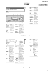
...decoder is set to "ANALOG" (page 63). Lights up when multi channel audio is set to store a station or enter the selection when selecting the settings (page 27). SECTION 1 GENERAL STR-K7100 This section is input through the OPTICAL jack. Lights up when ...2 34 5 67 SW LFE SP A ; Getting Started Description and location of parts Receiver Front panel 12 3 4 5 67 8 ? / 1 SPEAKERS (OFF/A/B/A+B) AUTO CAL MIC PHONES VIDEO 3 IN/PORTABLE AV IN VIDEO L AUDIO R MULTI CHANNEL DECODING DISPLAY INPUT MODE INPUT SELECTOR MASTER VOLUME MEMORY/ ENTER TUNING MODE TUNING 2CH A.F.D....
...decoder is set to "ANALOG" (page 63). Lights up when multi channel audio is set to store a station or enter the selection when selecting the settings (page 27). SECTION 1 GENERAL STR-K7100 This section is input through the OPTICAL jack. Lights up when ...2 34 5 67 SW LFE SP A ; Getting Started Description and location of parts Receiver Front panel 12 3 4 5 67 8 ? / 1 SPEAKERS (OFF/A/B/A+B) AUTO CAL MIC PHONES VIDEO 3 IN/PORTABLE AV IN VIDEO L AUDIO R MULTI CHANNEL DECODING DISPLAY INPUT MODE INPUT SELECTOR MASTER VOLUME MEMORY/ ENTER TUNING MODE TUNING 2CH A.F.D....
Service Manual
Page 22
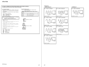
...Vp-p 12.5 MHz 1 V/DIV, 50 nsec/DIV 4 IC1501 9 (MCLK1) 1 V/DIV, 50 nsec/DIV 2.8 Vp-p 13.9 MHz 1 V/DIV, 50 nsec/DIV 1.7 Vp-p STR-K7100 22 22 Replace only with mark 0 are in µF unless otherwise noted. (p: pF) 50 WV or less are not indicated except for electrolytics and tantalums...face side seen from the side which enables seeing. Note: The components identified by mark 0 or dotted line with part number specified. • A : B+ Line. • B : B- STR-K7100 THIS NOTE IS COMMON FOR PRINTED WIRING BOARDS AND SCHEMATIC DIAGRAMS. (In addition to this, the necessary note is ...
...Vp-p 12.5 MHz 1 V/DIV, 50 nsec/DIV 4 IC1501 9 (MCLK1) 1 V/DIV, 50 nsec/DIV 2.8 Vp-p 13.9 MHz 1 V/DIV, 50 nsec/DIV 1.7 Vp-p STR-K7100 22 22 Replace only with mark 0 are in µF unless otherwise noted. (p: pF) 50 WV or less are not indicated except for electrolytics and tantalums...face side seen from the side which enables seeing. Note: The components identified by mark 0 or dotted line with part number specified. • A : B+ Line. • B : B- STR-K7100 THIS NOTE IS COMMON FOR PRINTED WIRING BOARDS AND SCHEMATIC DIAGRAMS. (In addition to this, the necessary note is ...

Service Manual
Page 55
CASE SECTION STR-K7100 The components identified by mark 0 or dotted line with mark 0 are critical for routine service. Replace only with part number specified. 2 1 front panel section #1 #1 #1 2 #1 #1 #1 #1 back panel section chassis section #1 Ref. Description 2-661-145-11 CASE 3-363-099-02 SCREW (CASE 3 TP2) Remark Ref. NOTE: • The mechanical parts with no reference...
CASE SECTION STR-K7100 The components identified by mark 0 or dotted line with mark 0 are critical for routine service. Replace only with part number specified. 2 1 front panel section #1 #1 #1 2 #1 #1 #1 #1 back panel section chassis section #1 Ref. Description 2-661-145-11 CASE 3-363-099-02 SCREW (CASE 3 TP2) Remark Ref. NOTE: • The mechanical parts with no reference...

Service Manual
Page 56
No. 51 52 53 54 55 Part No. Description X-2176-078-1 FRONT PANEL ASSY 4-977-358-01 CUSHION 2-661-142-01 KNOB (VOLUME) 2-661-141-01 KNOB (MENU) 3-087-053-01 +BVTP 2.6 (... 55 55 55 not supplied (VIDEO 3 board) FL101 supplied with RV101 58 54 53 supplied with RV102 57 not supplied 51 52 Ref. STR-K7100 6-2. No. 56 57 58 FL101 Part No. Description A-1223-144-A DISPLAY BOARD, COMPLETE 1-828-994-11 WIRE (FLAT TYPE) (17 CORE) 3-354-981-11 SPRING (SUS), RING 1-519...
No. 51 52 53 54 55 Part No. Description X-2176-078-1 FRONT PANEL ASSY 4-977-358-01 CUSHION 2-661-142-01 KNOB (VOLUME) 2-661-141-01 KNOB (MENU) 3-087-053-01 +BVTP 2.6 (... 55 55 55 not supplied (VIDEO 3 board) FL101 supplied with RV101 58 54 53 supplied with RV102 57 not supplied 51 52 Ref. STR-K7100 6-2. No. 56 57 58 FL101 Part No. Description A-1223-144-A DISPLAY BOARD, COMPLETE 1-828-994-11 WIRE (FLAT TYPE) (17 CORE) 3-354-981-11 SPRING (SUS), RING 1-519...

Service Manual
Page 57
...) (13 CORE) A-1158-394-A HDMI SW BOARD, COMPLETE * 106 3-703-244-00 BUSHING (2104), CORD Remark Ref. No. 0 107 108 TN1 #1 #2 Part No. No. 101 102 103 104 105 Part No. Description 1-783-820-11 1-828-935-11 1-693-728-11 7-685-646-79 7-685-871-01 CORD, POWER WIRE (FLAT TYPE...) (5 CORE) TUNER (FM/AM) (ANTENNA) SCREW +BVTP 3X8 TYPE2 IT-3 SCREW +BVTT 3X6 (S) #3 7-685-862-09 SCREW +BVTT 2.6X6 (S) Remark 57 BACK PANEL SECTION STR-K7100 not supplied...
...) (13 CORE) A-1158-394-A HDMI SW BOARD, COMPLETE * 106 3-703-244-00 BUSHING (2104), CORD Remark Ref. No. 0 107 108 TN1 #1 #2 Part No. No. 101 102 103 104 105 Part No. Description 1-783-820-11 1-828-935-11 1-693-728-11 7-685-646-79 7-685-871-01 CORD, POWER WIRE (FLAT TYPE...) (5 CORE) TUNER (FM/AM) (ANTENNA) SCREW +BVTP 3X8 TYPE2 IT-3 SCREW +BVTT 3X6 (S) #3 7-685-862-09 SCREW +BVTT 2.6X6 (S) Remark 57 BACK PANEL SECTION STR-K7100 not supplied...

Service Manual
Page 58
STR-K7100 6-4. Description A-1223-130-A MAIN BOARD, COMPLETE 3-905-609-01 SCREW (TRANSISTOR) A-1223-017-A DIGITAL BOARD, COMPLETE 4-977-358-01 CUSHION 3-077-331-21 +BV 3 (3-CR) Remark Ref. No. Q603 Q604 Q653 Q654 Q703 Part No. CHASSIS SECTION #1 156 156 T901 F901 not supplied (STANDBY board) not supplied (DCDC board) F4002 F4001 155...-MK TRANSFORMER, POWER (MAIN) SCREW +BVTP 3X8 TYPE2 IT-3 Q504 6-702-391-01 TRANSISTOR MP1620-OPY-MK Remark 58 No. 151 152 153 154 155 Part No.
STR-K7100 6-4. Description A-1223-130-A MAIN BOARD, COMPLETE 3-905-609-01 SCREW (TRANSISTOR) A-1223-017-A DIGITAL BOARD, COMPLETE 4-977-358-01 CUSHION 3-077-331-21 +BV 3 (3-CR) Remark Ref. No. Q603 Q604 Q653 Q654 Q703 Part No. CHASSIS SECTION #1 156 156 T901 F901 not supplied (STANDBY board) not supplied (DCDC board) F4002 F4001 155...-MK TRANSFORMER, POWER (MAIN) SCREW +BVTP 3X8 TYPE2 IT-3 Q504 6-702-391-01 TRANSISTOR MP1620-OPY-MK Remark 58 No. 151 152 153 154 155 Part No.
Service Manual
Page 59
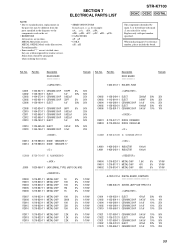
... 0.47uF 470uF 0.1uF 10% 50V 20% 10V 10% 50V 20% 10V 10% 25V 59 Some delay should be different from the parts specified in the diagrams or the components used on the set. • RESISTORS All resistors are seldom required for example: uA.. : ...181;F • COILS uH : µH STR-K7100 DCAC DCDC DIGITAL The components identified by reference number, please include the board. Ref. Description DCAC BOARD *********** Remark Ref. Part No. Part No. uPB.. : µPB.. When indicating parts by mark 0 or dotted line with part number specified. METAL OXIDE: Metal oxide-film resistor...
... 0.47uF 470uF 0.1uF 10% 50V 20% 10V 10% 50V 20% 10V 10% 25V 59 Some delay should be different from the parts specified in the diagrams or the components used on the set. • RESISTORS All resistors are seldom required for example: uA.. : ...181;F • COILS uH : µH STR-K7100 DCAC DCDC DIGITAL The components identified by reference number, please include the board. Ref. Description DCAC BOARD *********** Remark Ref. Part No. Part No. uPB.. : µPB.. When indicating parts by mark 0 or dotted line with part number specified. METAL OXIDE: Metal oxide-film resistor...
Service Manual
Page 61
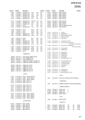
STR-K7100 DIGITAL Ref. Description 1-100-566-11 1-100-566-11 1-100-566-11 1-162-927-11 1-100-566-11 CERAMIC CHIP CERAMIC CHIP ... 8-759-096-87 6-600-466-01 6-600-466-01 6-707-608-01 8-759-710-97 IC TC7WU04FU (TE12R) IC TORX147L(SONY) (DIGITAL VIDEO 2/BD IN (OPTICAL)) IC TORX147L(SONY) (DIGITAL SAT IN (OPTICAL)) IC PCM1803DBR IC NJM4565M-D IC1404 IC1405 IC1452 IC1501 IC1502 8-759-710-97 8-759-710-97 6-708...11 METAL CHIP 100 R1012 1-216-809-11 METAL CHIP 100 R1013 1-216-809-11 METAL CHIP 100 5% 1/10W 5% 1/10W 5% 1/10W 5% 1/10W 61 Part No. No. C1620 C1661 C1667 C1702 C1703...
STR-K7100 DIGITAL Ref. Description 1-100-566-11 1-100-566-11 1-100-566-11 1-162-927-11 1-100-566-11 CERAMIC CHIP CERAMIC CHIP ... 8-759-096-87 6-600-466-01 6-600-466-01 6-707-608-01 8-759-710-97 IC TC7WU04FU (TE12R) IC TORX147L(SONY) (DIGITAL VIDEO 2/BD IN (OPTICAL)) IC TORX147L(SONY) (DIGITAL SAT IN (OPTICAL)) IC PCM1803DBR IC NJM4565M-D IC1404 IC1405 IC1452 IC1501 IC1502 8-759-710-97 8-759-710-97 6-708...11 METAL CHIP 100 R1012 1-216-809-11 METAL CHIP 100 R1013 1-216-809-11 METAL CHIP 100 5% 1/10W 5% 1/10W 5% 1/10W 5% 1/10W 61 Part No. No. C1620 C1661 C1667 C1702 C1703...
Service Manual
Page 64
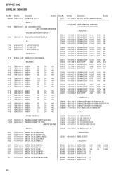
No. No. Part No. Description Remark S112 1-771-410-21 SWITCH, TACTILE (MEMORY/ENTER A-1158-394-A HDMI SW BOARD, COMPLETE...11 SHORT CHIP 0 64 Description CNS100 1-784-778-11 CONNECTOR, FFC 17P Remark < DIODE > D105 6-501-539-01 LED SELK5E20C-DTP15 (MULTI CHANNEL DECODING) < VACUUM FLUORESCENT DISPLAY > FL101 1-519-927-11 VACUUM FLUORESCENT DISPLAY < IC > IC100 IC101 IC103 8-759-643-83 IC uPD16315GB-3BS...-386-81 CARBON CARBON CARBON CARBON CARBON 10 5% 1/4W F 75 5% 1/4W 2.2K 5% 1/4W 2.7 5% 1/4W F 2.7 5% 1/4W F Ref. STR-K7100 DISPLAY HDMI SW Ref. Part No.
No. No. Part No. Description Remark S112 1-771-410-21 SWITCH, TACTILE (MEMORY/ENTER A-1158-394-A HDMI SW BOARD, COMPLETE...11 SHORT CHIP 0 64 Description CNS100 1-784-778-11 CONNECTOR, FFC 17P Remark < DIODE > D105 6-501-539-01 LED SELK5E20C-DTP15 (MULTI CHANNEL DECODING) < VACUUM FLUORESCENT DISPLAY > FL101 1-519-927-11 VACUUM FLUORESCENT DISPLAY < IC > IC100 IC101 IC103 8-759-643-83 IC uPD16315GB-3BS...-386-81 CARBON CARBON CARBON CARBON CARBON 10 5% 1/4W F 75 5% 1/4W 2.2K 5% 1/4W 2.7 5% 1/4W F 2.7 5% 1/4W F Ref. STR-K7100 DISPLAY HDMI SW Ref. Part No.

Service Manual
Page 65
... CERAMIC 33PF 1-162-927-11 CERAMIC CHIP 100PF 20% 50V 10% 25V 20% 50V 20% 10V 0.25PF 500V 10% 500V 5% 50V 65 No. STR-K7100 HDMI SW HEADPHONE MAIN Ref. Part No. No. Description R5008 1-216-864-11 SHORT CHIP 0 R5009 1-216-864-11 SHORT CHIP 0 R5010 1-216-864-11 SHORT CHIP 0 R5011... C485 C488 C492 C493 C495 C501 C503 C504 C505 C506 C507 C510 C511 C516 C517 C519 C529 C540 C541 C601 C603 C604 C605 C606 C607 Part No.
... CERAMIC 33PF 1-162-927-11 CERAMIC CHIP 100PF 20% 50V 10% 25V 20% 50V 20% 10V 0.25PF 500V 10% 500V 5% 50V 65 No. STR-K7100 HDMI SW HEADPHONE MAIN Ref. Part No. No. Description R5008 1-216-864-11 SHORT CHIP 0 R5009 1-216-864-11 SHORT CHIP 0 R5010 1-216-864-11 SHORT CHIP 0 R5011... C485 C488 C492 C493 C495 C501 C503 C504 C505 C506 C507 C510 C511 C516 C517 C519 C529 C540 C541 C601 C603 C604 C605 C606 C607 Part No.

Service Manual
Page 69
... 5% 1/10W 5% 1/10W 5% 1/10W Ref. R758 R759 R760 R761 R763 R764 R765 R766 R767 R768 R769 R770 R771 R772 R773 R775 R778 R780 R790 R791 Part No. No. Part No. Description Remark TM604 1-780-214-11 TERMINAL BOARD (SP) (2P) (SPEAKERS CENTER) POWER KEY BOARD < CONNECTOR > * CN103 1-691-670-11 CONNECTOR, BOARD TO...-240-11 TERMINAL BOARD (CHECKER PIN) (4P) (SPEAKERS FRONT B) D923 6-500-522-11 DIODE 10EDB40-TA2B5 < GROUND TERMINAL > G901 1-537-738-21 TERMINAL, GROUND 69 STR-K7100 MAIN POWER KEY STANDBY Ref.
... 5% 1/10W 5% 1/10W 5% 1/10W Ref. R758 R759 R760 R761 R763 R764 R765 R766 R767 R768 R769 R770 R771 R772 R773 R775 R778 R780 R790 R791 Part No. No. Part No. Description Remark TM604 1-780-214-11 TERMINAL BOARD (SP) (2P) (SPEAKERS CENTER) POWER KEY BOARD < CONNECTOR > * CN103 1-691-670-11 CONNECTOR, BOARD TO...-240-11 TERMINAL BOARD (CHECKER PIN) (4P) (SPEAKERS FRONT B) D923 6-500-522-11 DIODE 10EDB40-TA2B5 < GROUND TERMINAL > G901 1-537-738-21 TERMINAL, GROUND 69 STR-K7100 MAIN POWER KEY STANDBY Ref.

Service Manual
Page 70
No. Part No. Description < TRANSISTOR > Remark Ref. Description < DIODE > Remark Q901 8-729-119-78 TRANSISTOR 2SC2785-HFE Q921 8-729-119-78 TRANSISTOR 2SC2785-HFE D203 8-719-991-...-721-11 PIN, CONNECTOR (SMALL TYPE) 5P * CN202 1-690-880-31 LEAD (WITH CONNECTOR) < JACK > J298 1-819-187-11 JACK, PIN 3P (VIDEO 3 IN/PORTABLE AV IN VIDEO,AUDIO) 70 No. Part No. STR-K7100 STANDBY VIDEO VIDEO 3 Ref.
No. Part No. Description < TRANSISTOR > Remark Ref. Description < DIODE > Remark Q901 8-729-119-78 TRANSISTOR 2SC2785-HFE Q921 8-729-119-78 TRANSISTOR 2SC2785-HFE D203 8-719-991-...-721-11 PIN, CONNECTOR (SMALL TYPE) 5P * CN202 1-690-880-31 LEAD (WITH CONNECTOR) < JACK > J298 1-819-187-11 JACK, PIN 3P (VIDEO 3 IN/PORTABLE AV IN VIDEO,AUDIO) 70 No. Part No. STR-K7100 STANDBY VIDEO VIDEO 3 Ref.


