Service Manual
Page 5
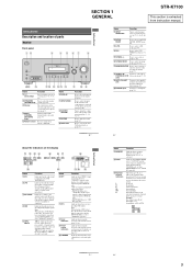
...qg qf qd qs qa q; 9 Name A ?/1 (on/standby) B SPEAKERS (OFF/A/B/A+B) C Display D MULTI CHANNEL DECODING lamp E Remote sensor Function Press to turn the receiver on the display if no digital signal is actually being input through the OPTICAL jack. - The current status ...location of parts Receiver Front panel 12 3 4 5 67 8 ? / 1 SPEAKERS (OFF/A/B/A+B) AUTO CAL MIC PHONES VIDEO 3 IN/PORTABLE AV IN VIDEO L AUDIO R MULTI CHANNEL DECODING DISPLAY INPUT MODE INPUT SELECTOR MASTER VOLUME MEMORY/ ENTER TUNING MODE TUNING 2CH A.F.D. SECTION 1 GENERAL STR-K7100 This section is...
...qg qf qd qs qa q; 9 Name A ?/1 (on/standby) B SPEAKERS (OFF/A/B/A+B) C Display D MULTI CHANNEL DECODING lamp E Remote sensor Function Press to turn the receiver on the display if no digital signal is actually being input through the OPTICAL jack. - The current status ...location of parts Receiver Front panel 12 3 4 5 67 8 ? / 1 SPEAKERS (OFF/A/B/A+B) AUTO CAL MIC PHONES VIDEO 3 IN/PORTABLE AV IN VIDEO L AUDIO R MULTI CHANNEL DECODING DISPLAY INPUT MODE INPUT SELECTOR MASTER VOLUME MEMORY/ ENTER TUNING MODE TUNING 2CH A.F.D. SECTION 1 GENERAL STR-K7100 This section is...
Service Manual
Page 6
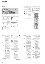
...(R) Yellow VIDEO IN/ OUT jacka) Connects the video and audio jacks of the AV ?/1 switch changes automatically each time you press ?/1 (B) at the same time (...channels of the VCR, CD player, VCD player, LD player, DVD player, MD deck, DAT deck, tape deck, Blu-ray disc recorder, PSX, DVD/VHS COMBO, or DVD/HDD COMBO. O F1, F2 Press F1 or F2 to select a component to a DVD IN jack player, etc. Then, use . STR-K7100... Sony TV, press TV (Z) and then press MENU. Then, use the supplied remote to operate the receiver and to control the Sony audio/video components that the remote...
...(R) Yellow VIDEO IN/ OUT jacka) Connects the video and audio jacks of the AV ?/1 switch changes automatically each time you press ?/1 (B) at the same time (...channels of the VCR, CD player, VCD player, LD player, DVD player, MD deck, DAT deck, tape deck, Blu-ray disc recorder, PSX, DVD/VHS COMBO, or DVD/HDD COMBO. O F1, F2 Press F1 or F2 to select a component to a DVD IN jack player, etc. Then, use . STR-K7100... Sony TV, press TV (Z) and then press MENU. Then, use the supplied remote to operate the receiver and to control the Sony audio/video components that the remote...
Service Manual
Page 7
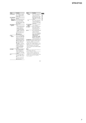
... described. • The AUX on the remote is displayed on the component, the above explanation is also available for receiver operation. 13US Getting Started STR-K7100 7 Press to the previous menu. -... - Press to select the category mode for Sony TVs only. Press also, to clear a mistake when you press the incorrect numeric button of the receiver, VCR, satellite tuner, CD player, DVD player... the remote. To select the channel entry mode of the CD player, VCD player, DVD player or MD deck (multi-disc changer only). Press to enter the selection. It changes the remote key...
... described. • The AUX on the remote is displayed on the component, the above explanation is also available for receiver operation. 13US Getting Started STR-K7100 7 Press to the previous menu. -... - Press to select the category mode for Sony TVs only. Press also, to clear a mistake when you press the incorrect numeric button of the receiver, VCR, satellite tuner, CD player, DVD player... the remote. To select the channel entry mode of the CD player, VCD player, DVD player or MD deck (multi-disc changer only). Press to enter the selection. It changes the remote key...
Service Manual
Page 20
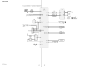
STR-K7100 5-7. J2000 AUTO CAL MIC MIC AMP IC2000 5 1 SYSTEM CONTROL IC1907 (5/6) 113 DCAC IN XM SECTION H (Page 19) XM MOXMI XM MIXMO EEPROM IC1131 SDA 5 SCL 6 ... 14 SEG1 I I 29 SEG17 • 31 GRID1 42 II GRID11 32 SW1 1 SIRCS 2 OUT REMOTE CONTROL SIGNAL RECEIVER IC103 2 RV102 3 MASTER VOLUME F1 FL101 F2 VACUUM FLUORESCENT DISPLAY LED DRIVER Q110 D105 MULTI CHANNEL DECODING 2 RV101 3 INPUT SELECTOR SW NETWORK S101-108 SW NETWORK S109-112,115 STR-K7100 20 20 BLOCK DIAGRAM - KEY/DISPLAY SECTION -
STR-K7100 5-7. J2000 AUTO CAL MIC MIC AMP IC2000 5 1 SYSTEM CONTROL IC1907 (5/6) 113 DCAC IN XM SECTION H (Page 19) XM MOXMI XM MIXMO EEPROM IC1131 SDA 5 SCL 6 ... 14 SEG1 I I 29 SEG17 • 31 GRID1 42 II GRID11 32 SW1 1 SIRCS 2 OUT REMOTE CONTROL SIGNAL RECEIVER IC103 2 RV102 3 MASTER VOLUME F1 FL101 F2 VACUUM FLUORESCENT DISPLAY LED DRIVER Q110 D105 MULTI CHANNEL DECODING 2 RV101 3 INPUT SELECTOR SW NETWORK S101-108 SW NETWORK S109-112,115 STR-K7100 20 20 BLOCK DIAGRAM - KEY/DISPLAY SECTION -
Service Manual
Page 39
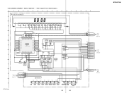
... M BOARD (2/3) CNS511 (Page 29) CNP106 2P CL004 1 2 DCAC IN DCAC IN Q DCAC BOARD CN2000 5 (Page 37) STR-K7100 F. SCHEMATIC DIAGRAM - 5-26. DISPLAY SECTION - • Refer to page 47 for IC Block Diagrams. 1 2 3 4 5...GND 35 GRID8 7G -18.2 36 GRID7 SEG8 21 -12.5 7P SEG7 20 REMOTE CONTROL SIGNAL RECEIVER 6G -18.2 -6.9 6P 123 D 37 GRID6 5G -18.2 38 GRID5 4G...C111 220p C110 220p VDD IC101 IC101 TC74ACT08P BUFFER Q110 D105 F 2SC1740S-QRT SELK5E20C-DTP15 LED DRIVER M U LT I CHANNEL DECODING 5 3 5 0 1 2 3 4 5 6 7 5 0 R115 100 R116 100 R117 100 C149 220p ...
... M BOARD (2/3) CNS511 (Page 29) CNP106 2P CL004 1 2 DCAC IN DCAC IN Q DCAC BOARD CN2000 5 (Page 37) STR-K7100 F. SCHEMATIC DIAGRAM - 5-26. DISPLAY SECTION - • Refer to page 47 for IC Block Diagrams. 1 2 3 4 5...GND 35 GRID8 7G -18.2 36 GRID7 SEG8 21 -12.5 7P SEG7 20 REMOTE CONTROL SIGNAL RECEIVER 6G -18.2 -6.9 6P 123 D 37 GRID6 5G -18.2 38 GRID5 4G...C111 220p C110 220p VDD IC101 IC101 TC74ACT08P BUFFER Q110 D105 F 2SC1740S-QRT SELK5E20C-DTP15 LED DRIVER M U LT I CHANNEL DECODING 5 3 5 0 1 2 3 4 5 6 7 5 0 R115 100 R116 100 R117 100 C149 220p ...
Service Manual
Page 51
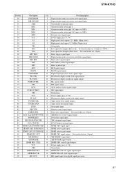
STR-K7100 Pin No. Pin Name I/O 49 DIR ERROR I 50 DIR XSTATE I 51 NMI I 52 MD2 I 53 MD1 I...speed clock output (Sub clock) Not used in this set. (Open) Reset trigger signal input Digital audio interface receiver serial data signal input Burst select signal output GP9 address strobe signal input Burst signal output HCS signal output HACN...V) Fluorescent display serial latch signal output Tuner serial clock signal output Tuner serial data signal output Stop signal input Remote control signal input Error select signal input Not used in this set. (Open) XMDB power control signal output ...
STR-K7100 Pin No. Pin Name I/O 49 DIR ERROR I 50 DIR XSTATE I 51 NMI I 52 MD2 I 53 MD1 I...speed clock output (Sub clock) Not used in this set. (Open) Reset trigger signal input Digital audio interface receiver serial data signal input Burst select signal output GP9 address strobe signal input Burst signal output HCS signal output HACN...V) Fluorescent display serial latch signal output Tuner serial clock signal output Tuner serial data signal output Stop signal input Remote control signal input Error select signal input Not used in this set. (Open) XMDB power control signal output ...


