Sony STR-K7100 Support Question
Sony STR-K7100 Support Question
Find answers below for this question about Sony STR-K7100 - Multi Channel Av Receiver.Need a Sony STR-K7100 manual? We have 1 online manual for this item!
Question posted by navejaselijah6 on December 26th, 2022
What Is The Remote Code For The Sony Str-k7100?
I have a universal remote and would like to use it with my sony str-k7100 but I do not know the remote code
Current Answers
Answer #1: Posted by SonuKumar on December 26th, 2022 6:56 PM
SonuKumar

Member since:
May 9th, 2021 Points: 16,598,000

Member since:
May 9th, 2021 Points: 16,598,000
Please respond to my effort to provide you with the best possible solution by using the "Acceptable Solution" and/or the "Helpful" buttons when the answer has proven to be helpful.
Regards,
Sonu
Your search handyman for all e-support needs!!
Related Sony STR-K7100 Manual Pages
Service Manual - Page 1
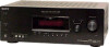
...receiver incorporates High-Definition Multimedia Interface (HDMITM) technology.
MULTI CHANNEL AV RECEIVER
9-887-608-01 2007C04-1 © 2007.03
Sony Corporation
Home Audio Division Published by Sony... watts per channel minimum RMS power, with no sound output.
SERVICE MANUAL
Ver. 1.0 2007.03
STR-K7100
US Model
Manufactured under the following conditions:
Area code US
Power ...
Service Manual - Page 2
...SONY.
2 All preset stations will be erased when you change without notice.
COMPONENTS IDENTIFIED BY MARK 0 OR DOTTED LINE WITH MARK 0 ON THE SCHEMATIC DIAGRAMS AND IN THE PARTS LIST ARE CRITICAL TO SAFE OPERATION. STR-K7100...turn off the receiver.
While holding down TUNING MODE, press ?/1. SAFETY-RELATED COMPONENT WARNING!! Video section Inputs/Outputs
Video: COMPONENT VIDEO:
1 ...
Service Manual - Page 3
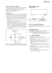
... parts for a slightly longer time. Leakage current can be used but unleaded solder may also be damaged
by any exposed metal part having a return to about 40°C higher than
ordinary solder. Check leakage as the Simpson 229 or RCA
WT-540A. STR-K7100
SAFETY CHECK-OUT (US MODEL) After correcting the original...
Service Manual - Page 4
...5-28. Tuner/Audio Section 15 5-3. XM Section 19 5-7. Schematic Diagram - Key/Display Section 20 5-8. Printed Wiring Board - XM Section 35 5-22. Schematic Diagram - Schematic Diagram - FM TUNER CHECK 13
5. Main Section 23 5-10. Printed Wiring Boards - DISASSEMBLY 2-1. Digital Section (2/2 27 5-14. Back Panel Section 57 6-4. STR-K7100
TABLE OF...
Service Manual - Page 5
... mute the sound (page 34).
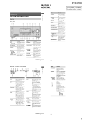
SECTION 1 GENERAL
STR-K7100
This section is input through the OPTICAL jack. MOVIE
MUSIC
AUTO CAL
MUTING
w;ql
qk
qj qh qg qf qd qs
qa
q; 9
Name A ?/1
(on/standby)
B SPEAKERS (OFF/A/B/A+B)
C Display
D MULTI CHANNEL DECODING lamp
E Remote sensor
Function
Press to turn the receiver on the display (page 68).
Turn to...
Service Manual - Page 6
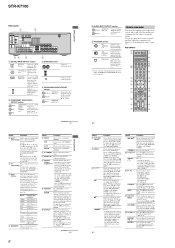
...Sony TV, press TV (Z) and then press MENU.
Press to pause playback or recording of all components,
press ?/1 and AV ?/1 (A) at
the same time (SYSTEM
STANDBY).
Press TV (Z) and then press TV/CH +/- STR-K7100...use the supplied remote to operate the receiver and to control the Sony audio/video components that the
remote... Press to select
the TV channels. You can enjoy high quality...
Service Manual - Page 7
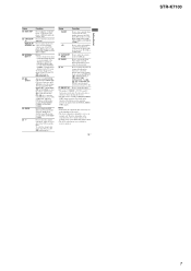
...remote key function to serve as references when operating the receiver. Use the tactile dots as an example only.
return to select the category mode for receiver operation, press V/v/B/b to select the channel... Z TV
wj RM SET UP
Press to perform menu operations for receiver operation.
13US
Getting Started
STR-K7100
7 It also activate the DISPLAY (J), OPTIONS TOOLS (K), MENU (L), ...
Service Manual - Page 8
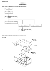
FRONT PANEL SECTION (Page 9)
2-4. STR-K7100
SECTION 2 DISASSEMBLY
Note : This set can be disassemble according to the following sequence. CASE (Page 8)
2-2. CASE
2 two screws (case 3 TP2)
3 two screws (+BVTP 3 × 8)
4 case
1 ...
Service Manual - Page 9
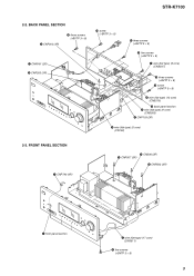
... screw (+BVTP 3 × 8)
8 wire (flat type) (13 core) (CNS510)
qg back panel section 6 wire (flat type) (9 core)
(CNS503) 5 CNP103 (3P)
4 wire (flat type) (5 core) (CN102)
2-3. STR-K7100
2-2.
Service Manual - Page 10
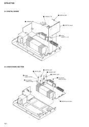
DIGITAL BOARD
2 CNP503 (8P)
1 CNP505 (7P)
3 CNP512 (3P)
5 DIGITAL board
4 screw (+BVTP 3 × 8)
2-5. MAIN BOARD SECTION
4 CN915 (6P)
5 screw (+BV3 (3-CR)) 6 two screws (+BV3 (3-CR))
3 CNP912 (2P) 1 CNP801 (5P) 2 CNP802 (5P)
7 two screws (+BV3 (3-CR))
8 MAIN board section
10 STR-K7100
2-4.
Service Manual - Page 12
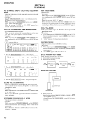
..., all buttons are pressed "REST 00" appears. Use this mode before returning the product to clients upon completion of any button other than the ?/1 counts down the buttons. Receiver
DCAC MIC
SPK Front Left 1. SW LFE
SP ...to the default setting. * Procedure: 1. "DCAC[]FTM" appears. STR-K7100
SECTION 3 TEST MODE
AM CHANNEL STEP 9 kHz/10 kHz SELECTION MODE * Either the 9 kHz step or 10...
Service Manual - Page 14
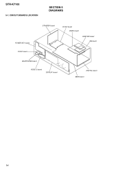
STR-K7100
5-1. CIRCUIT BOARDS LOCATION
SECTION 5 DIAGRAMS
POWER KEY board DCAC board
STANDBY board
DCDC board VIDEO board
HDMI SW board XM board
HEADPHONE board
VIDEO 3 board
DISPLAY board
DIGITAL board MAIN board
14
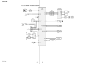
Service Manual - Page 17
...IN
PB/CB
-9 PR/CR
VIDEO 1 DVD SAT
-1 J201 (1/2) VIDEO
IN
-2 J200 (1/2) VIDEO
IN
-1 VIDEO
IN
VIDEO 3 IN/ PORTABLE AV IN
J298 (1/2) -1
VIDEO
COMPONENT VIDEO SELECT IC304
1 CH1 IN1 3 CH1 IN2 5 CH1 IN3 7 CH2 IN1 9 CH2 IN2 11 CH2 IN3 16 CH3 IN1 14 CH3 IN2... V COMP SW2 28 V MUTE 34 V_SW1 33 V_SW2 32 V_SW3 31 V_SW4
• Signal path : VIDEO
STR-K7100
STR-K7100
17
17 VIDEO SECTION - 5-4.
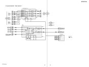
Service Manual - Page 20
...
97 EEPROM DATA 98 EEPROM CLK
FL_LAT 78 FL_DATA 71
FL_CLK 70
SIRCS IN 82
TUNER/AUDIO SECTION (Page 15)
F
C LINK RX C LINK TX
CNS504
9
8
FLASH
1
...REMOTE CONTROL SIGNAL RECEIVER
IC103
2
RV102
3
MASTER VOLUME
F1
FL101
F2
VACUUM
FLUORESCENT
DISPLAY
LED DRIVER
Q110
D105
MULTI CHANNEL DECODING
2
RV101
3
INPUT SELECTOR
SW NETWORK S101-108
SW NETWORK S109-112,115
STR-K7100...
Service Manual - Page 21
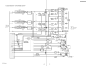
...STR-K7100
STR-K7100
21
21 BLOCK DIAGRAM - L-CH R-CH R-CH
PRE DRIVER IC701
IN 2 8
PRE DRIVE
DRIVE
+VOUT2 -VOUT2 12
11
-45V +B
POWER AMP Q701-704
SL-CH
SR-CH R-CH
TUNER/
AUDIO...TB001 (1/2)
L FRONT A
R
TM602
L FRONT B
R TB001 (2/2)
SPEAKERS
IMPEDANCE USE 6-16Ω
L
SURROUND R
TM604
CENTER
J309
AUDIO OUT
SUB WOOFER
T901
POWER
TRANSFORMER (MAIN)
• Signal path
: TUNER (...
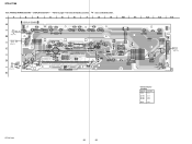
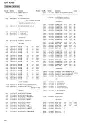
Service Manual - Page 38
... JW149
5
2
Q110 BE
S104 DISPLAY
JW111 R122 R131
D105 MULTI CHANNEL DECODING
R197
E
JW128 C164
JW132
10
11
12
13
14...DISPLAY SECTION - • Refer to page 14 for Circuit Boards Location.
1
2
3
4
5
6
7
: Uses unleaded solder.
8
9
DISPLAY BOARD
A
TP102
R110
DCAC
BOARD CN2000
Q
5
(Page 37)
CL201 CNP106
GRY
2...
Q110
D-8
STR-K7100
38
38 STR-K7100
5-25.
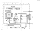
Service Manual - Page 39
...2P
CL004 1
2
DCAC IN DCAC IN
Q DCAC BOARD CN2000
5
(Page 37)
STR-K7100 DISPLAY SECTION - • Refer to page 47 for IC Block Diagrams.
1
2
3... GRID7
SEG8 21 -12.5 7P
SEG7 20
REMOTE CONTROL SIGNAL RECEIVER
6G -18.2
-6.9
6P
123
D
37 ... TC74ACT08P
BUFFER
Q110
D105
F
2SC1740S-QRT SELK5E20C-DTP15
LED DRIVER
M U LT I
CHANNEL
DECODING
5
3
5
0
1
2
3
4
5
6
7
5
0
R115 100...
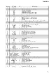
Service Manual - Page 51
...OUT
I
Pin Description Digital audio interface receiver error signal input Digital audio interface receiver state signal input Non ...used in this set. (Connect to GND.) Low speed clock output (Sub clock) Not used in this set. (Open) Reset trigger signal input Digital audio interface receiver... Remote control signal input Error select signal input Not used in... CEC signal output Not used in this set. (...
Service Manual - Page 61
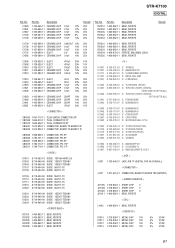
...-096-87 6-600-466-01
6-600-466-01
6-707-608-01 8-759-710-97
IC TC7WU04FU (TE12R) IC TORX147L(SONY) (DIGITAL
VIDEO 2/BD IN (OPTICAL)) IC TORX147L(SONY) (DIGITAL
SAT IN (OPTICAL)) IC PCM1803DBR IC NJM4565M-D
IC1404 IC1405 IC1452 IC1501 IC1502
8-759-710-97 8-759-710-97... CHIP
0.1uF 0.1uF 0.1uF 100PF 0.1uF
Remark
10% 25V 10% 25V 10% 25V 5% 50V 10% 25V
Ref. Part No. STR-K7100
DIGITAL
Ref.
Service Manual - Page 64
STR-K7100
DISPLAY HDMI SW
Ref. Description
Remark
S112 1-771-410-21 SWITCH, TACTILE (MEMORY/ENTER
A-1158-...CHIP 0
64 No.
Description
CNS100 1-784-778-11 CONNECTOR, FFC 17P
Remark
< DIODE >
D105 6-501-539-01 LED SELK5E20C-DTP15 (MULTI CHANNEL DECODING)
< VACUUM FLUORESCENT DISPLAY >
FL101 1-519-927-11 VACUUM FLUORESCENT DISPLAY
< IC >
IC100 IC101 IC103
8-759-643-83 IC ...
Similar Questions

How To Unlock My Str-k7100 Receiver
My son was playing with the remote to my receiver and now I have no sound. I turned it off and back ...
My son was playing with the remote to my receiver and now I have no sound. I turned it off and back ...
(Posted by Riddickchae 6 years ago)

Sony Multi Channel Av Receiver Str-dg800
Where can I fond the ON/OFF power button for the Sony Multi Channel AV Receiver STR-DG800?
Where can I fond the ON/OFF power button for the Sony Multi Channel AV Receiver STR-DG800?
(Posted by denverliverpool 7 years ago)

How To Connect To Laptop Sony Multi Channel Av Receiver Str-k7100
(Posted by Tiadrober 9 years ago)

Sony Multi Channel Av Receiver Str-dh520 How To Program Speakers
(Posted by chucdc 10 years ago)

Suddenly My Str-k7100 Receiver Will Not Turn On.
Suddenly my receiver will not turn on, fine one day then will not power on the next. I am sure the 1...
Suddenly my receiver will not turn on, fine one day then will not power on the next. I am sure the 1...
(Posted by tman165 11 years ago)