Sony STR-K7100 Support Question
Sony STR-K7100 Support Question
Find answers below for this question about Sony STR-K7100 - Multi Channel Av Receiver.Need a Sony STR-K7100 manual? We have 1 online manual for this item!
Question posted by tman165 on October 10th, 2012
Suddenly My Str-k7100 Receiver Will Not Turn On.
Suddenly my receiver will not turn on, fine one day then will not power on the next. I am sure the 110 outlet is fine. Is there something that I could possibly check before throwing it out? It is too old to have repaired.
Current Answers
Related Sony STR-K7100 Manual Pages
Service Manual - Page 1
...
- "DTS" and "DTS Digital Surround" are trademarks or registered trademarks of DTS, Inc.
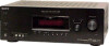
rated 90 watts per channel minimum RMS power, with no sound output.
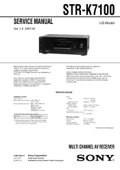
MULTI CHANNEL AV RECEIVER
9-887-608-01 2007C04-1 © 2007.03
Sony Corporation
Home Audio Division Published by Sony Techno Create Corporation
1 The XM name and related logos are trademarks of XM...
Service Manual - Page 2
...turn off the receiver.
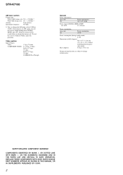
REPLACE THESE COMPONENTS...General Power requirements
Area code US
Power requirements 120 V AC, 60 Hz
Power output (DIGITAL MEDIA PORT)
DC OUT:
5 V, 700 mA
Power consumption
Area code US
Power consumption 170 W
Power ...THE PARTS LIST ARE CRITICAL TO SAFE OPERATION. SAFETY-RELATED COMPONENT WARNING!! STR-K7100
AM tuner section
Tuning range
With 10-kHz tuning scale...
Service Manual - Page 3
...
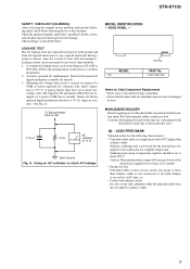
Notes on Chip Component Replacement • Never reuse a disconnected chip component. • Notice that is more viscous (sticky, less prone to any one of three methods. 1. STR-K7100
SAFETY CHECK-OUT (US MODEL...parts for this job. 3.
Ordinary soldering irons can be set to the customer: Check the antenna terminals, metal trim, "metallized" knobs, screws, and all battery operated...
Service Manual - Page 5
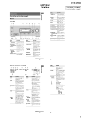
SECTION 1 GENERAL
STR-K7100
This section is connected. Press to select information displayed on the display (page 68). The current status of the selected component or a list of all speakers ... Lights up when multi channel audio is decoding DTS signals. Lights up when using the receiver to turn the receiver on the display if no digital signal is selected. Receives signals from the ...
Service Manual - Page 6
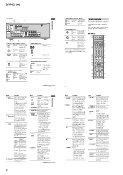
... 5a)) - Press to start playback of all components,
press ?/1 and AV ?/1 (A) at the
same time, it will turn the receiver on or
(on/standby) off the audio/
(on the TV screen. Press to display ...menu operations.
select preset channels of the VCR, DAT deck, or tape deck. Press TV (Z) and then press TV VOL to a DVD
IN jack
player, etc.
STR-K7100
Rear panel
1
2
DIGITAL...
Service Manual - Page 7
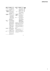
...deck (multi-disc ...RECEIVER (D), then press MENU (L) for receiver operation.
13US
Getting Started
STR-K7100
7 Press also, to select track numbers over 10 of the receiver... and the duration which the receiver turns off automatically.
Press to enter...component, the above operation may not be possible...channel entry mode of the VCR or satellite tuner.
To return to select the channel...
Service Manual - Page 12
... S SR
k Hz
m ft. LFE SP B
x COAX
NEO:6
RDS D.RANGE MONO
k m MHz
3. CLR." Receiver
DCAC MIC
SPK Front Left 1. Afterward, press the [TUNING MODE] to turn off the set AM and press the ?/1 button to turn on . STR-K7100
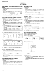
SECTION 3 TEST MODE
AM CHANNEL STEP 9 kHz/10 kHz SELECTION MODE * Either the 9 kHz step or 10 kHz...
Service Manual - Page 13
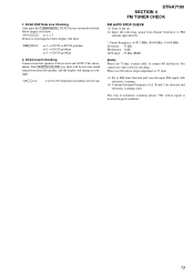
... signal with automatic scanning.
(4) Confirm that input Frequency of the receiver and AUTO CAL microphone. The stop of automatic scanning means "The station signal is 75 ohm.
(3) Set to 255 (depends on loudness of test tone)
STR-K7100 SECTION 4 FM TUNER CHECK
FM AUTO STOP CHECK (1) Turn on the set . You cannot use 75 ohm "coaxial...
Service Manual - Page 20
...X0
97 EEPROM DATA 98 EEPROM CLK
FL_LAT 78 FL_DATA 71
FL_CLK 70
SIRCS IN 82
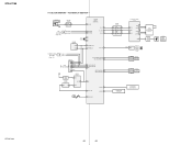
TUNER/AUDIO SECTION (Page 15)
F
C LINK RX C LINK TX
CNS504
9
8
FLASH
1
PROGRAMMING ...SIGNAL RECEIVER
IC103
2
RV102
3
MASTER VOLUME
F1
FL101
F2
VACUUM
FLUORESCENT
DISPLAY
LED DRIVER
Q110
D105
MULTI CHANNEL DECODING
2
RV101
3
INPUT SELECTOR
SW NETWORK S101-108
SW NETWORK S109-112,115
STR-K7100
20
...
Service Manual - Page 28
...STR-K7100
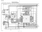
• Refer to page 22 for Waveforms. • Refer to page 48 for IC Block Diagrams. 5-14. DIGITAL SECTION (1/3) - • Refer to page 42 for IC Pin Description.
1
2
3
4
5
6
7
8
9
DIGITAL BOARD (1/3) A
10
11
12
13
14
15
16
F B 1 3 0 90 u H
B
C2281 470 10V
C1316 0.1
IC1354
C
OPTICAL
F B 1 3 5 00 u H
RECEIVER...AUDIO INTERFACE RECEIVER...108
109
110
111
112...
Service Manual - Page 37
... BOARD
S115
D
SPEAKERS
CN103
R111 680
5P
S100
1 AD1
/
2 PW_SW
DISPLAY
3 GND
R BOARD
CN104
4 TUNING-JOG-A
(Page 39)
5 TUNING-JOG-B
H
STR-K7100
37
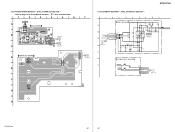
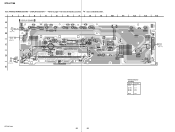
37 5-23. PRINTED WIRING BOARDS - SCHEMATIC DIAGRAM - DCAC, POWER KEY SECTION -
• Refer to page 14 for Circuit Boards Location.
: Uses unleaded solder.
1
2
3
4
5
6
7
J2000 AUTO CAL MIC
A
DCAC BOARD
A001...
Service Manual - Page 38
... C-8
Q110
D-8
STR-K7100
38
38 R105...JW149
5
2
Q110 BE
S104 DISPLAY
JW111 R122 R131
D105 MULTI CHANNEL DECODING
R197
E
JW128 C164
JW132
10
11
12
13
...
DCAC
BOARD CN2000
Q
5
(Page 37)
CL201 CNP106
GRY
2 CL004 1
JW143
S112 MEMORY/
ENTER
B
CL024
CN104
POWER KEY BOARD
R
CN103
(Page 37)
CL022
1
CL023
CL063
5 CL064
CL066
JW159 JW136 JW129 JW161
CL065
C
CL032 CL031...
Service Manual - Page 39
...CNP106 2P
CL004 1
2
DCAC IN DCAC IN
Q DCAC BOARD CN2000
5
(Page 37)
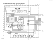
STR-K7100 5-26. DISPLAY SECTION - • Refer to page 47 for IC Block Diagrams.
1
...21 -12.5 7P
SEG7 20
REMOTE CONTROL SIGNAL RECEIVER
6G -18.2
-6.9
6P
123
D
37 GRID6 ...
CHANNEL
DECODING
5
3
5
0
1
2
3
4
5
6
7
5
0
R115 100 R116 100 R117 100
C149 220p C164 220p
CN104
5P
G
AD1 1
CL022 CL023
POWER ...
Service Manual - Page 40
...-72
D915 1SS133T-72
R921 47k
D910-913 RECT
C921 0.1
C922 0.1
8
6
F901 5A 125V
T902 POWER TRANSFORMER (SUB)
4
3
1
G901
E
(CHASSIS)
D901 1SS133T-72
RY901 JW905
CNP902 2P 1
2
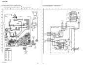
LIVE NEUTRAL
CNP901 3P
1 LIVE
R901 3.3M
3 NEUTRAL
AC IN '
40 STR-K7100
5-27. Location
D901
D-1
D910
G-3
D911
G-2
D912
G-2
D913
G-2
D914
G-2
D915
G-2
D920
E-5
D921
E-5
D922
E-5
D923...
Service Manual - Page 48
... from system control IC
38, 39
GP13, GP14
O Not used. (Open)
40
VDDI
I Power supply pin (+1.9 V)
41
VSS
- Ground pin
42
GP15
O Not used. (Open)
43
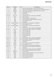
... from digital audio interface receiver IC
31
VSS
- Ground pin
9
MCLK1
I Clock signal input (13.9 MHz)
10
VDDI
I /O
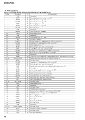
Pin Description
1
VSS
-
Ground pin
2
XRST
I Boot stop signal input
48 STR-K7100
• IC...
Service Manual - Page 49
... for SDRAM IC
I/O External memory data input/output for system control IC
I Audio signal input from digital audio interface receiver IC
I Power supply pin (+1.9 V)
- STR-K7100
Pin No. 57 58 59 60 61
62, 63 64 to 66
67 ...68 69 70 71 72 to 75 76 77 to 80 81 82 83 to 85 86 87 88 89 90 91 92 to 97 98, 99 100 101 102 to 105 106 107, 108 109, 110...
Service Manual - Page 50
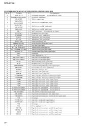
...SW2
O Video component select switch control signal output 2
30
V COMP SW1
O Video component select switch ...audio interface receiver reset signal output
39
DIR CLK SEL
O Digital audio interface receiver serial clock select signal output
40
VSS
- Ground pin
44
VCC
- STR-K7100...
HP DETECT
I Headphone detect signal input
9
POWER RY
O Power relay control signal output
10
VOL CL
O ...
Service Manual - Page 51
STR-K7100
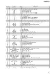
Pin No. Pin Name
I/O
49
DIR ERROR
I
50
DIR XSTATE
I
51
NMI
I
52
MD2
I
53
MD1... signal input Digital audio interface receiver state signal input Non Maskable interrupt input Operation mode setting pin 2 Operation mode setting pin 1 (Connect to GND.) Operation mode setting pin 0 (Connect to GND.) External reset signal input Power supply pin (+3.3 V) High speed clock output (...
Service Manual - Page 53
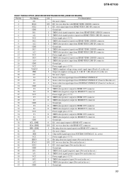
... from HDMI VIDEO 2/BD IN connector
4
GND
- Power supply pin (+3.3 V)
28
Y3
O TMDS data (...Power supply pin (+3.3 V)
51
B32
I TMDS data (negative) input (Not used in this set .)
52
A32
I TMDS data (positive) input (Not used . (Open)
2
SDA1
I/O I2C two-way data bus with HDMI OUT connector
40
HPD_SINK
I /O
Pin Description
1
NC
- STR-K7100
IC5001 TMDS341PFCR (HDMI RECEIVER...
Service Manual - Page 64
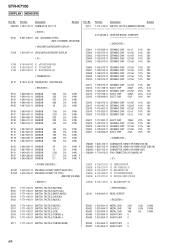
...-864-11 SHORT CHIP 0 R5007 1-216-864-11 SHORT CHIP 0
64 Part No. No.
STR-K7100
DISPLAY HDMI SW
Ref.
No. Description
CNS100 1-784-778-11 CONNECTOR, FFC 17P
Remark
< DIODE >
D105 6-501-539-01 LED SELK5E20C-DTP15 (MULTI CHANNEL DECODING)
< VACUUM FLUORESCENT DISPLAY >
FL101 1-519-927-11 VACUUM FLUORESCENT DISPLAY
< IC >
IC100 IC101...
Similar Questions

What Is The Remote Code For The Sony Str-k7100?
I have a universal remote and would like to use it with my sony str-k7100 but I do not know the remo...
I have a universal remote and would like to use it with my sony str-k7100 but I do not know the remo...
(Posted by navejaselijah6 1 year ago)
How To Unlock My Str-k7100 Receiver
My son was playing with the remote to my receiver and now I have no sound. I turned it off and back ...
My son was playing with the remote to my receiver and now I have no sound. I turned it off and back ...
(Posted by Riddickchae 6 years ago)

Sony Multi Channel Av Receiver Str-dg800
Where can I fond the ON/OFF power button for the Sony Multi Channel AV Receiver STR-DG800?
Where can I fond the ON/OFF power button for the Sony Multi Channel AV Receiver STR-DG800?
(Posted by denverliverpool 7 years ago)

How To Connect To Laptop Sony Multi Channel Av Receiver Str-k7100
(Posted by Tiadrober 9 years ago)
Multi Channel Av Receiver Str Dh510
Turns on like normal. After 5 minutes it makes a pop noise and turns off. I can turn it back on but ...
Turns on like normal. After 5 minutes it makes a pop noise and turns off. I can turn it back on but ...
(Posted by Megelineau 11 years ago)