Service Manual
Page 1
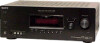
...SPECIFICATIONS POWER OUTPUT AND TOTAL HARMONIC DISTORTION: With 6 ohm loads, both channels driven, from Dolby Laboratories. MULTI CHANNEL AV RECEIVER 9-887-608-01 2007C04-1 © 2007.03 Sony Corporation Home Audio Division Published by Sony Techno Create Corporation 1 The XM name and related logos are trademarks ... 1% total harmonic distortion from 250 milliwatts to rated output. rated 90 watts per channel minimum RMS power, with no sound output. SERVICE MANUAL Ver. 1.0 2007.03 STR-K7100 US Model Manufactured under the following conditions: Area code US Power requirements 120 V ...
...SPECIFICATIONS POWER OUTPUT AND TOTAL HARMONIC DISTORTION: With 6 ohm loads, both channels driven, from Dolby Laboratories. MULTI CHANNEL AV RECEIVER 9-887-608-01 2007C04-1 © 2007.03 Sony Corporation Home Audio Division Published by Sony Techno Create Corporation 1 The XM name and related logos are trademarks ... 1% total harmonic distortion from 250 milliwatts to rated output. rated 90 watts per channel minimum RMS power, with no sound output. SERVICE MANUAL Ver. 1.0 2007.03 STR-K7100 US Model Manufactured under the following conditions: Area code US Power requirements 120 V ...
Service Manual
Page 2
...scale to 9 kHz or 10 kHz. All preset stations will be erased when you change without notice. SAFETY-RELATED COMPONENT WARNING!! STR-K7100 AM tuner section Tuning range With 10-kHz tuning scale: 530 - 1,710 kHz 3) With 9-kHz tuning scale: 531 -...to 10 kHz (or 9 kHz), repeat the procedure. REPLACE THESE COMPONENTS WITH SONY PARTS WHOSE PART NUMBERS APPEAR AS SHOWN IN THIS MANUAL OR IN SUPPLEMENTS PUBLISHED BY SONY. 2 COMPONENTS IDENTIFIED BY MARK 0 OR DOTTED LINE WITH MARK 0 ON THE... subject to change the tuning scale. After tuning in any AM station, turn off the receiver.
...scale to 9 kHz or 10 kHz. All preset stations will be erased when you change without notice. SAFETY-RELATED COMPONENT WARNING!! STR-K7100 AM tuner section Tuning range With 10-kHz tuning scale: 530 - 1,710 kHz 3) With 9-kHz tuning scale: 531 -...to 10 kHz (or 9 kHz), repeat the procedure. REPLACE THESE COMPONENTS WITH SONY PARTS WHOSE PART NUMBERS APPEAR AS SHOWN IN THIS MANUAL OR IN SUPPLEMENTS PUBLISHED BY SONY. 2 COMPONENTS IDENTIFIED BY MARK 0 OR DOTTED LINE WITH MARK 0 ON THE... subject to change the tuning scale. After tuning in any AM station, turn off the receiver.
Service Manual
Page 5
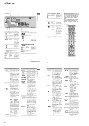
...connections and that INPUT MODE is set to adjust the volume level of parts Receiver Front panel 12 3 4 5 67 8 ? / 1 SPEAKERS (OFF/A/B/A+B) AUTO CAL MIC PHONES VIDEO 3 IN/PORTABLE AV IN VIDEO L AUDIO R MULTI CHANNEL DECODING DISPLAY INPUT MODE INPUT SELECTOR MASTER VOLUME MEMORY/ ENTER TUNING MODE TUNING ... show how the receiver downmixes the source sound. SECTION 1 GENERAL STR-K7100 This section is output from the SUB WOOFER jack. PL" lights up when the disc being input through the COAXIAL jack, or when INPUT MODE is not set to turn the receiver on the display...
...connections and that INPUT MODE is set to adjust the volume level of parts Receiver Front panel 12 3 4 5 67 8 ? / 1 SPEAKERS (OFF/A/B/A+B) AUTO CAL MIC PHONES VIDEO 3 IN/PORTABLE AV IN VIDEO L AUDIO R MULTI CHANNEL DECODING DISPLAY INPUT MODE INPUT SELECTOR MASTER VOLUME MEMORY/ ENTER TUNING MODE TUNING ... show how the receiver downmixes the source sound. SECTION 1 GENERAL STR-K7100 This section is output from the SUB WOOFER jack. PL" lights up when the disc being input through the COAXIAL jack, or when INPUT MODE is not set to turn the receiver on the display...
Service Manual
Page 6
... jack to a TV or a projector (page 22). The buttons are output to a TV (page 19). Press to display the menu of the AV ?/1 switch changes automatically each time you want to use the V/v/B/b and to operate. Press TV (Z) and then press TV/CH +/- select preset stations... numeric buttons of Sony TV, press TV (Z) and then press DISPLAY. to the FM wire antenna supplied with this receiver (page 26). select track numbers of the TV, press TV (Z) and then press MUTING. 12US F ANTENNA section FM ANTENNA jack Connects to select preset TV channels. STR-K7100 Rear panel 1 ...
... jack to a TV or a projector (page 22). The buttons are output to a TV (page 19). Press to display the menu of the AV ?/1 switch changes automatically each time you want to use the V/v/B/b and to operate. Press TV (Z) and then press TV/CH +/- select preset stations... numeric buttons of Sony TV, press TV (Z) and then press DISPLAY. to the FM wire antenna supplied with this receiver (page 26). select track numbers of the TV, press TV (Z) and then press MUTING. 12US F ANTENNA section FM ANTENNA jack Connects to select preset TV channels. STR-K7100 Rear panel 1 ...
Service Manual
Page 7
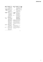
...satellite tuner. Press to select the channel entry mode, either one or two digit of Sony TV, press TV (Z) and then press RETURN/EXIT O. Press to - Press to select the category for receiver operation, press V/v/B/b to enter the...the previous menu. - return to enter the selection of the CD player, VCD player, DVD player or MD deck (multi-disc changer only). For details on -screen guide of the TV, DVD player, Satellite tuner, Blu-ray disc recorder,... on the component, the above explanation is also available for receiver operation. 13US Getting Started STR-K7100 7
...satellite tuner. Press to select the channel entry mode, either one or two digit of Sony TV, press TV (Z) and then press RETURN/EXIT O. Press to - Press to select the category for receiver operation, press V/v/B/b to enter the...the previous menu. - return to enter the selection of the CD player, VCD player, DVD player or MD deck (multi-disc changer only). For details on -screen guide of the TV, DVD player, Satellite tuner, Blu-ray disc recorder,... on the component, the above explanation is also available for receiver operation. 13US Getting Started STR-K7100 7
Service Manual
Page 12
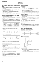
STR-K7100 SECTION 3 TEST MODE AM CHANNEL STEP 9 kHz/10 kHz SELECTION MODE * Either the 9 kHz step or 10 kHz step can be swap to all channel so that all segments light on at the same time, then each segment lights on one after another. * Procedure: While depressing the [... the [INPUT SELECTOR] control, all buttons are pressed "REST 00" appears. Use this mode before returning the product to turn on the main power. Receiver DCAC MIC SPK Front Left 1. DCAC FACTORY TEST MODE DCAC Factory Test mode have sound output. * Procedure: 1. SOFTWARE VERSION DISPLAY MODE * The software...
STR-K7100 SECTION 3 TEST MODE AM CHANNEL STEP 9 kHz/10 kHz SELECTION MODE * Either the 9 kHz step or 10 kHz step can be swap to all channel so that all segments light on at the same time, then each segment lights on one after another. * Procedure: While depressing the [... the [INPUT SELECTOR] control, all buttons are pressed "REST 00" appears. Use this mode before returning the product to turn on the main power. Receiver DCAC MIC SPK Front Left 1. DCAC FACTORY TEST MODE DCAC Factory Test mode have sound output. * Procedure: 1. SOFTWARE VERSION DISPLAY MODE * The software...
Service Manual
Page 13
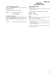
...automatic scanning. (4) Confirm that input Frequency of test tone) STR-K7100 SECTION 4 FM TUNER CHECK FM AUTO STOP CHECK (1) Turn on loudness of A, B and C are detected and automatic scanning stops. The stop of the receiver and AUTO CAL microphone. You cannot use SG whose output...DSP Data Line Checking After press the [TUNING MODE], DCAC Factory test mode will start, below display will show: "DCAC[][][]x" x=1, 2, 3 If there is received in good condition." 13 DCAC board Checking Connect front left speaker, and the display will show: "ERR[]SD0x" x=1 t D1501 or R1530 problem x=2 t...
...automatic scanning. (4) Confirm that input Frequency of test tone) STR-K7100 SECTION 4 FM TUNER CHECK FM AUTO STOP CHECK (1) Turn on loudness of A, B and C are detected and automatic scanning stops. The stop of the receiver and AUTO CAL microphone. You cannot use SG whose output...DSP Data Line Checking After press the [TUNING MODE], DCAC Factory test mode will start, below display will show: "DCAC[][][]x" x=1, 2, 3 If there is received in good condition." 13 DCAC board Checking Connect front left speaker, and the display will show: "ERR[]SD0x" x=1 t D1501 or R1530 problem x=2 t...
Service Manual
Page 20
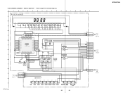
... 7 DIN 8 CLK 14 SEG1 I I 29 SEG17 • 31 GRID1 42 II GRID11 32 SW1 1 SIRCS 2 OUT REMOTE CONTROL SIGNAL RECEIVER IC103 2 RV102 3 MASTER VOLUME F1 FL101 F2 VACUUM FLUORESCENT DISPLAY LED DRIVER Q110 D105 MULTI CHANNEL DECODING 2 RV101 3 INPUT SELECTOR SW NETWORK S101-108 SW NETWORK S109-112,115 STR-K7100 20 20 BLOCK DIAGRAM...
... 7 DIN 8 CLK 14 SEG1 I I 29 SEG17 • 31 GRID1 42 II GRID11 32 SW1 1 SIRCS 2 OUT REMOTE CONTROL SIGNAL RECEIVER IC103 2 RV102 3 MASTER VOLUME F1 FL101 F2 VACUUM FLUORESCENT DISPLAY LED DRIVER Q110 D105 MULTI CHANNEL DECODING 2 RV101 3 INPUT SELECTOR SW NETWORK S101-108 SW NETWORK S109-112,115 STR-K7100 20 20 BLOCK DIAGRAM...
Service Manual
Page 28
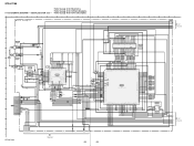
...STR-K7100 • Refer to page 22 for Waveforms. • Refer to page 48 for IC Block Diagrams. 5-14. DIGITAL SECTION (1/3) - • Refer to page 42 for IC Pin Description. 1 2 3 4 5 6 7 8 9 DIGITAL BOARD (1/3) A 10 11 12 13 14 15 16 F B 1 3 0 90 u H B C2281 470 10V C1316 0.1 IC1354 C OPTICAL F B 1 3 5 00 u H RECEIVER... (2/3) A-7 A-8 (Page 29) A-9 A-19 A-10 A-11 A-12 A-13 A-14 A-15 A-16 A-17 A-18 2 DIGITAL BOARD (2/3) (Page 29) B-1 B-2 B-3 B-4 B-5 B-13 B-7 B-10 B-9 B-11 B-12 L STR-K7100 3 DIGITAL BOARD (3/3) (Page 30) 28 28 SCHEMATIC DIAGRAM -
...STR-K7100 • Refer to page 22 for Waveforms. • Refer to page 48 for IC Block Diagrams. 5-14. DIGITAL SECTION (1/3) - • Refer to page 42 for IC Pin Description. 1 2 3 4 5 6 7 8 9 DIGITAL BOARD (1/3) A 10 11 12 13 14 15 16 F B 1 3 0 90 u H B C2281 470 10V C1316 0.1 IC1354 C OPTICAL F B 1 3 5 00 u H RECEIVER... (2/3) A-7 A-8 (Page 29) A-9 A-19 A-10 A-11 A-12 A-13 A-14 A-15 A-16 A-17 A-18 2 DIGITAL BOARD (2/3) (Page 29) B-1 B-2 B-3 B-4 B-5 B-13 B-7 B-10 B-9 B-11 B-12 L STR-K7100 3 DIGITAL BOARD (3/3) (Page 30) 28 28 SCHEMATIC DIAGRAM -
Service Manual
Page 39
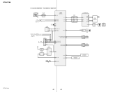
... DIGITAL M BOARD (2/3) CNS511 (Page 29) CNP106 2P CL004 1 2 DCAC IN DCAC IN Q DCAC BOARD CN2000 5 (Page 37) STR-K7100 F. D . DISPLAY SECTION - • Refer to page 47 for IC Block Diagrams. 1 2 3 4 5 6 7 8 9...35 GRID8 7G -18.2 36 GRID7 SEG8 21 -12.5 7P SEG7 20 REMOTE CONTROL SIGNAL RECEIVER 6G -18.2 -6.9 6P 123 D 37 GRID6 5G -18.2 38 GRID5 4G -18...220p C111 220p C110 220p VDD IC101 IC101 TC74ACT08P BUFFER Q110 D105 F 2SC1740S-QRT SELK5E20C-DTP15 LED DRIVER M U LT I CHANNEL DECODING 5 3 5 0 1 2 3 4 5 6 7 5 0 R115 100 R116 100 R117 100 C149 220p C164 ...
... DIGITAL M BOARD (2/3) CNS511 (Page 29) CNP106 2P CL004 1 2 DCAC IN DCAC IN Q DCAC BOARD CN2000 5 (Page 37) STR-K7100 F. D . DISPLAY SECTION - • Refer to page 47 for IC Block Diagrams. 1 2 3 4 5 6 7 8 9...35 GRID8 7G -18.2 36 GRID7 SEG8 21 -12.5 7P SEG7 20 REMOTE CONTROL SIGNAL RECEIVER 6G -18.2 -6.9 6P 123 D 37 GRID6 5G -18.2 38 GRID5 4G -18...220p C111 220p C110 220p VDD IC101 IC101 TC74ACT08P BUFFER Q110 D105 F 2SC1740S-QRT SELK5E20C-DTP15 LED DRIVER M U LT I CHANNEL DECODING 5 3 5 0 1 2 3 4 5 6 7 5 0 R115 100 R116 100 R117 100 C149 220p C164 ...
Service Manual
Page 48
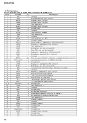
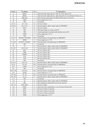
...control IC 3 EXTIN I Not used. (Connect to ground.) 4 LRCKI3 I Not used . (Open) 40 VDDI I GP12 signal input from digital audio interface receiver IC 31 VSS - Ground pin 2 XRST I Not used. (Connect to ground.) 55 TST1 O Not used . (Open) 8 VSS - Ground pin 49...Open) 54 BOOT I Not used. (Connect to ground.) 7 PLOCK O Not used . (Open) 56 BST I Power supply pin (+1.9 V) 11 VSS - STR-K7100 • IC Pin Descriptions IC1501 CXD9718BQ (DIGITAL SIGNAL PROCESSOR) (DIGITAL BOARD (1/3)) Pin No. Ground pin 9 MCLK1 I Clock signal input (13.9 MHz) 10...
...control IC 3 EXTIN I Not used. (Connect to ground.) 4 LRCKI3 I Not used . (Open) 40 VDDI I GP12 signal input from digital audio interface receiver IC 31 VSS - Ground pin 2 XRST I Not used. (Connect to ground.) 55 TST1 O Not used . (Open) 8 VSS - Ground pin 49...Open) 54 BOOT I Not used. (Connect to ground.) 7 PLOCK O Not used . (Open) 56 BST I Power supply pin (+1.9 V) 11 VSS - STR-K7100 • IC Pin Descriptions IC1501 CXD9718BQ (DIGITAL SIGNAL PROCESSOR) (DIGITAL BOARD (1/3)) Pin No. Ground pin 9 MCLK1 I Clock signal input (13.9 MHz) 10...
Service Manual
Page 49
...) O External memory address signal output for SDRAM IC O Not used. (Open) O GP9 signal output for system control IC I Audio signal input from digital audio interface receiver IC I /O External memory data input/output for SDRAM IC I Power supply pin (+3.3 V) I Power supply pin (+1.9 V) - Ground pin I/O External memory data input... used. (Fixed at H.) I Not used. (Fixed at H.) I Not used. (Connect to ground.) I Not used. (Connect to ground.) I Not used . (Open) I Power supply pin (+1.9 V) - STR-K7100 Pin No. 57 58 59 60 61 62, 63 64 to 66 67 68 69 70 71 72 to 75 76 77 to 80 81...
...) O External memory address signal output for SDRAM IC O Not used. (Open) O GP9 signal output for system control IC I Audio signal input from digital audio interface receiver IC I /O External memory data input/output for SDRAM IC I Power supply pin (+3.3 V) I Power supply pin (+1.9 V) - Ground pin I/O External memory data input... used. (Fixed at H.) I Not used. (Fixed at H.) I Not used. (Connect to ground.) I Not used. (Connect to ground.) I Not used . (Open) I Power supply pin (+1.9 V) - STR-K7100 Pin No. 57 58 59 60 61 62, 63 64 to 66 67 68 69 70 71 72 to 75 76 77 to 80 81...
Service Manual
Page 50
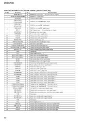
STR-K7100 IC1907 MB91353APMT-G-112E1 (SYSTEM CONTROL) (DIGITAL BOARD (2/3)) Pin No. Ground pin 19 VCC - Power supply pin (+3.3 V) 20 INPUT ENCODER A I Input select encoder signal input A 21 ... input B Not used in this set . 37 PCM1609 RESET O A/D and D/A converters reset signal output 38 DIR XMODE O Digital audio interface receiver reset signal output 39 DIR CLK SEL O Digital audio interface receiver serial clock select signal output 40 VSS - Ground pin 41 TC74HC153A O Input select switch control signal output A 42 TC74HC153B O Input...
STR-K7100 IC1907 MB91353APMT-G-112E1 (SYSTEM CONTROL) (DIGITAL BOARD (2/3)) Pin No. Ground pin 19 VCC - Power supply pin (+3.3 V) 20 INPUT ENCODER A I Input select encoder signal input A 21 ... input B Not used in this set . 37 PCM1609 RESET O A/D and D/A converters reset signal output 38 DIR XMODE O Digital audio interface receiver reset signal output 39 DIR CLK SEL O Digital audio interface receiver serial clock select signal output 40 VSS - Ground pin 41 TC74HC153A O Input select switch control signal output A 42 TC74HC153B O Input...
Service Manual
Page 51
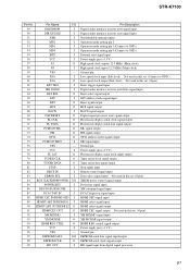
...VSS - 97 EEPROM DATA I/O 98 EEPROM CLK O 99 HD OUT I Pin Description Digital audio interface receiver error signal input Digital audio interface receiver state signal input Non Maskable interrupt input Operation mode setting pin 2 Operation mode setting pin 1 (Connect ... output (Sub clock) Not used in this set. (Open) Reset trigger signal input Digital audio interface receiver serial data signal input Burst select signal output GP9 address strobe signal input Burst signal output HCS signal output... clock signal output HD signal input from digital signal processor 51 STR-K7100 Pin No.
...VSS - 97 EEPROM DATA I/O 98 EEPROM CLK O 99 HD OUT I Pin Description Digital audio interface receiver error signal input Digital audio interface receiver state signal input Non Maskable interrupt input Operation mode setting pin 2 Operation mode setting pin 1 (Connect ... output (Sub clock) Not used in this set. (Open) Reset trigger signal input Digital audio interface receiver serial data signal input Burst select signal output GP9 address strobe signal input Burst signal output HCS signal output... clock signal output HD signal input from digital signal processor 51 STR-K7100 Pin No.
Service Manual
Page 53
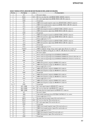
... Z2 O TMDS data (negative) output for HDMI OUT connector 30 GND - Pin Name I TMDS data (positive) input from HDMI OUT connector 41 NC - STR-K7100 IC5001 TMDS341PFCR (HDMI RECEIVER/TRANSCEIVER) (HDMI SW BOARD) Pin No. Ground pin 38 SCL_SINK O I2C clock signal output for HDMI OUT connector 39 SDA_SINK I/O I2C two-way data...
... Z2 O TMDS data (negative) output for HDMI OUT connector 30 GND - Pin Name I TMDS data (positive) input from HDMI OUT connector 41 NC - STR-K7100 IC5001 TMDS341PFCR (HDMI RECEIVER/TRANSCEIVER) (HDMI SW BOARD) Pin No. Ground pin 38 SCL_SINK O I2C clock signal output for HDMI OUT connector 39 SDA_SINK I/O I2C two-way data...


