Service Manual
Page 1
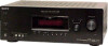
... name and related logos are trademarks or registered trademarks of XM Satellite Radio Inc. MULTI CHANNEL AV RECEIVER 9-887-608-01 2007C04-1 © 2007.03 Sony Corporation Home Audio Division Published by Sony Techno Create Corporation 1 "Dolby", "Pro Logic" and the double-D symbol are ...20,000 Hz; SERVICE MANUAL Ver. 1.0 2007.03 STR-K7100 US Model Manufactured under the following conditions: Area code US Power requirements 120 V AC, 60 Hz 2) Reference power output for front, center and surround speakers. SPECIFICATIONS Inputs Analog Sensitivity: 800 mV/ 50 kohms...
... name and related logos are trademarks or registered trademarks of XM Satellite Radio Inc. MULTI CHANNEL AV RECEIVER 9-887-608-01 2007C04-1 © 2007.03 Sony Corporation Home Audio Division Published by Sony Techno Create Corporation 1 "Dolby", "Pro Logic" and the double-D symbol are ...20,000 Hz; SERVICE MANUAL Ver. 1.0 2007.03 STR-K7100 US Model Manufactured under the following conditions: Area code US Power requirements 120 V AC, 60 Hz 2) Reference power output for front, center and surround speakers. SPECIFICATIONS Inputs Analog Sensitivity: 800 mV/ 50 kohms...
Service Manual
Page 5
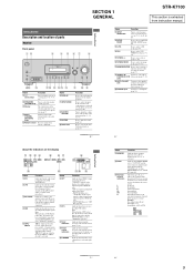
... STR-K7100 This section is output from the SUB WOOFER jack. MOVIE MUSIC AUTO CAL MUTING w;ql qk qj qh qg qf qd qs qa q; 9 Name A ?/1 (on/standby) B SPEAKERS (OFF/A/B/A+B) C Display D MULTI CHANNEL DECODING lamp E Remote sensor Function Press to turn the receiver ...reproduced. The current status of the selected component or a list of parts Receiver Front panel 12 3 4 5 67 8 ? / 1 SPEAKERS (OFF/A/B/A+B) AUTO CAL MIC PHONES VIDEO 3 IN/PORTABLE AV IN VIDEO L AUDIO R MULTI CHANNEL DECODING DISPLAY INPUT MODE INPUT SELECTOR MASTER VOLUME MEMORY/ ENTER TUNING MODE ...
... STR-K7100 This section is output from the SUB WOOFER jack. MOVIE MUSIC AUTO CAL MUTING w;ql qk qj qh qg qf qd qs qa q; 9 Name A ?/1 (on/standby) B SPEAKERS (OFF/A/B/A+B) C Display D MULTI CHANNEL DECODING lamp E Remote sensor Function Press to turn the receiver ...reproduced. The current status of the selected component or a list of parts Receiver Front panel 12 3 4 5 67 8 ? / 1 SPEAKERS (OFF/A/B/A+B) AUTO CAL MIC PHONES VIDEO 3 IN/PORTABLE AV IN VIDEO L AUDIO R MULTI CHANNEL DECODING DISPLAY INPUT MODE INPUT SELECTOR MASTER VOLUME MEMORY/ ENTER TUNING MODE ...
Service Manual
Page 6
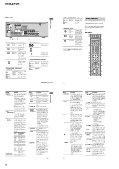
...TV RM SET UP AV ?/1 ? / 1 SYSTEM STANDBY VIDEO 1 VIDEO 2 VIDEO 3 DVD SAT TV SA-CD/CD TUNER 1 2 3 AUX DMPORT RECEIVER 4 2CH A.F.D. To display the menus of Sony TV, press TV ...RECEIVER Press to display the menus of the TV, VCR, VCD player, LD player, DVD player, CD player, MD deck, Blu-ray disc recorder, PSX, satellite tuner, DVD/VHS COMBO or DVD/ HDD COMBO. STR-K7100... SUB WOOFER FRONT B R FRONT A SPEAKERS L R SURROUND CENTER 65 4 A DIGITAL INPUT/OUTPUT section OPTICAL Connects to select the TV channels. To turn off all speakers at the same time (SYSTEM STANDBY). ray...
...TV RM SET UP AV ?/1 ? / 1 SYSTEM STANDBY VIDEO 1 VIDEO 2 VIDEO 3 DVD SAT TV SA-CD/CD TUNER 1 2 3 AUX DMPORT RECEIVER 4 2CH A.F.D. To display the menus of Sony TV, press TV ...RECEIVER Press to display the menus of the TV, VCR, VCD player, LD player, DVD player, CD player, MD deck, Blu-ray disc recorder, PSX, satellite tuner, DVD/VHS COMBO or DVD/ HDD COMBO. STR-K7100... SUB WOOFER FRONT B R FRONT A SPEAKERS L R SURROUND CENTER 65 4 A DIGITAL INPUT/OUTPUT section OPTICAL Connects to select the TV channels. To turn off all speakers at the same time (SYSTEM STANDBY). ray...
Service Manual
Page 12
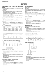
...DISPLAY MODE * The software version is activated, all buttons are pressed "REST 00" appears. Receiver DCAC MIC SPK Front Left 1. SBL SB SBR MHz KEY CHECK MODE * Button check * Procedure: While depressing the [SPEAKERS $OFF/A/B%] and the [2CH] buttons simultaneously, press the ?/1 button to turn on the ...or "10k STEP" appears for a moment. "DCAC[]FTM" appears. VACUUM FLUORESCENT DISPLAY TEST MODE * All fluorescent segments are not counted again. STR-K7100 SECTION 3 TEST MODE AM CHANNEL STEP 9 kHz/10 kHz SELECTION MODE * Either the 9 kHz step or 10 kHz step can be swap to all...
...DISPLAY MODE * The software version is activated, all buttons are pressed "REST 00" appears. Receiver DCAC MIC SPK Front Left 1. SBL SB SBR MHz KEY CHECK MODE * Button check * Procedure: While depressing the [SPEAKERS $OFF/A/B%] and the [2CH] buttons simultaneously, press the ?/1 button to turn on the ...or "10k STEP" appears for a moment. "DCAC[]FTM" appears. VACUUM FLUORESCENT DISPLAY TEST MODE * All fluorescent segments are not counted again. STR-K7100 SECTION 3 TEST MODE AM CHANNEL STEP 9 kHz/10 kHz SELECTION MODE * Either the 9 kHz step or 10 kHz step can be swap to all...
Service Manual
Page 13
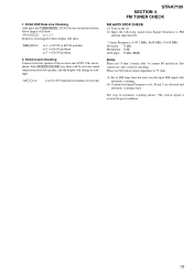
... there is 75 ohm. (3) Set to FM tuner function and scan the input FM signal with automatic scanning. (4) Confirm that input Frequency of test tone) STR-K7100 SECTION 4 FM TUNER CHECK FM AUTO STOP CHECK (1) Turn on loudness of A, B and C are detected and automatic scanning stops. You cannot use SG ... : 35 dBu (EMF) (Note) Please use 75 ohm "coaxial cable" to 255 (depends on the set. (2) Input the following signal from front left speaker of automatic scanning means "The station signal is received in good condition." 13 "AD[]-[]xxx" xxx=0 to connect SG and the set. The stop of the...
... there is 75 ohm. (3) Set to FM tuner function and scan the input FM signal with automatic scanning. (4) Confirm that input Frequency of test tone) STR-K7100 SECTION 4 FM TUNER CHECK FM AUTO STOP CHECK (1) Turn on loudness of A, B and C are detected and automatic scanning stops. You cannot use SG ... : 35 dBu (EMF) (Note) Please use 75 ohm "coaxial cable" to 255 (depends on the set. (2) Input the following signal from front left speaker of automatic scanning means "The station signal is received in good condition." 13 "AD[]-[]xxx" xxx=0 to connect SG and the set. The stop of the...
Service Manual
Page 21
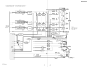
... Q611 RY710 RELAY DRIVER Q610 RY601 RELAY DRIVER Q612 RY610 RELAY DRIVER Q560 RY560 R-CH R-CH R-CH R-CH J790 PHONES TB001 (1/2) L FRONT A R TM602 L FRONT B R TB001 (2/2) SPEAKERS IMPEDANCE USE 6-16Ω L SURROUND R TM604 CENTER J309 AUDIO OUT SUB WOOFER T901 POWER TRANSFORMER (MAIN) • Signal path : TUNER (FM/AM) • R-ch is... D805-808 F1 F2 -20V RY901 R811 F901 R910 D804 T902 POWER TRANSFORMER (SUB) AC IN DETECT Q921 RECT D910-913 D914 D915 AC IN ~ STR-K7100 STR-K7100 21 21 OUTPUT/POWER SECTION - 5-8. BLOCK DIAGRAM -
... Q611 RY710 RELAY DRIVER Q610 RY601 RELAY DRIVER Q612 RY610 RELAY DRIVER Q560 RY560 R-CH R-CH R-CH R-CH J790 PHONES TB001 (1/2) L FRONT A R TM602 L FRONT B R TB001 (2/2) SPEAKERS IMPEDANCE USE 6-16Ω L SURROUND R TM604 CENTER J309 AUDIO OUT SUB WOOFER T901 POWER TRANSFORMER (MAIN) • Signal path : TUNER (FM/AM) • R-ch is... D805-808 F1 F2 -20V RY901 R811 F901 R910 D804 T902 POWER TRANSFORMER (SUB) AC IN DETECT Q921 RECT D910-913 D914 D915 AC IN ~ STR-K7100 STR-K7100 21 21 OUTPUT/POWER SECTION - 5-8. BLOCK DIAGRAM -

Service Manual
Page 23
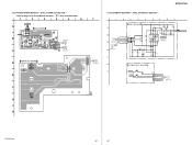
... Refer to page 14 for Circuit Boards Location. 1 2 3 4 5 6 7 : Uses unleaded solder. 8 9 10 11 12 13 14 A TM602 SPEAKERS IMPEDANCE USE 6-16Ω TB001 FRONT A SURROUND TM604 CENTER L L L J405 J403 J402 J309 FRONT B R R R SA-CD/CD/CD-R TV SAT... -4 L R BOARD R R R R R R R C400 C403 R405 R457 C XM T BOARD CN102 (Page 35) D DIGITAL A BOARD CNS501 (Page 27) E DIGITAL B BOARD F CNS502 (Page 27) G H STR-K7100 C444 R406 R408 R456 R407 R458 C458 JW308 R409 JW506 C3037 R830 D818 JW521 JW522 R459 C459 JW525 JW526 R471 C409 R472 C3024 C3034 JW460...
... Refer to page 14 for Circuit Boards Location. 1 2 3 4 5 6 7 : Uses unleaded solder. 8 9 10 11 12 13 14 A TM602 SPEAKERS IMPEDANCE USE 6-16Ω TB001 FRONT A SURROUND TM604 CENTER L L L J405 J403 J402 J309 FRONT B R R R SA-CD/CD/CD-R TV SAT... -4 L R BOARD R R R R R R R C400 C403 R405 R457 C XM T BOARD CN102 (Page 35) D DIGITAL A BOARD CNS501 (Page 27) E DIGITAL B BOARD F CNS502 (Page 27) G H STR-K7100 C444 R406 R408 R456 R407 R458 C458 JW308 R409 JW506 C3037 R830 D818 JW521 JW522 R459 C459 JW525 JW526 R471 C409 R472 C3024 C3034 JW460...

Service Manual
Page 25
... 15k 1SS355WTE-17 R525 -36.8 68k R529 C529 10k 0.01 R539 100k D529 1SS355WTE-17 R585 4.7k R586 47k STR-K7100 25 25 12 13 14 15 16 R792 6801W RY791 R794 680 1W 55 R793 82 D791 1SS355WTE-17 Q790 2SC3052EF-... RY801 R830 82 D818 1SS355WTE-17 R824 2.2k 69 Q809 2SC3052EF-T1-LEF RELAY DRIVER TM604 Q722,723,725,793,795 PROTECTOR RED BLK TM604 SPEAKERS IMPEDANCE USE 6-16Ω + CENTER - O P Y- M K Q654 M P 1 6 2 0 - O P Y- O P Y- M K Q703 M N 2 4 8 8 - MAIN SECTION (2/2) - • Refer to page 42 for IC Block Diagrams. 1 2 3 4 5 6 7 8 MAIN BOARD (2/2) A...
... 15k 1SS355WTE-17 R525 -36.8 68k R529 C529 10k 0.01 R539 100k D529 1SS355WTE-17 R585 4.7k R586 47k STR-K7100 25 25 12 13 14 15 16 R792 6801W RY791 R794 680 1W 55 R793 82 D791 1SS355WTE-17 Q790 2SC3052EF-... RY801 R830 82 D818 1SS355WTE-17 R824 2.2k 69 Q809 2SC3052EF-T1-LEF RELAY DRIVER TM604 Q722,723,725,793,795 PROTECTOR RED BLK TM604 SPEAKERS IMPEDANCE USE 6-16Ω + CENTER - O P Y- M K Q654 M P 1 6 2 0 - O P Y- O P Y- M K Q703 M N 2 4 8 8 - MAIN SECTION (2/2) - • Refer to page 42 for IC Block Diagrams. 1 2 3 4 5 6 7 8 MAIN BOARD (2/2) A...
Service Manual
Page 37
... TP2000 C2011 RED R2017 CL2004 1 11 G BOARD CN506 1-4 C 1-872-426- (11) (Page 23) POWER KEY BOARD D S115 TP100 SPEAKERS (OFF/A/B/A+B) E R111 JW180 CN103 1 5 DISPLAY R BOARD CN104 (Page 38) F S100 l / G 11 1-872-432- (11) STR-K7100 5-24. DCAC, POWER KEY SECTION - 1 A MAIN G B O A R D (1/2) CN506 B (Page 24) DISPLAY Q B O A R D...033 R2007 10k J2000 AUTO CAL MIC POWER KEY BOARD S115 D SPEAKERS CN103 R111 680 5P S100 1 AD1 / 2 PW_SW DISPLAY 3 GND R BOARD CN104 4 TUNING-JOG-A (Page 39) 5 TUNING-JOG-B H STR-K7100 37 37 PRINTED WIRING BOARDS - 5-23.
... TP2000 C2011 RED R2017 CL2004 1 11 G BOARD CN506 1-4 C 1-872-426- (11) (Page 23) POWER KEY BOARD D S115 TP100 SPEAKERS (OFF/A/B/A+B) E R111 JW180 CN103 1 5 DISPLAY R BOARD CN104 (Page 38) F S100 l / G 11 1-872-432- (11) STR-K7100 5-24. DCAC, POWER KEY SECTION - 1 A MAIN G B O A R D (1/2) CN506 B (Page 24) DISPLAY Q B O A R D...033 R2007 10k J2000 AUTO CAL MIC POWER KEY BOARD S115 D SPEAKERS CN103 R111 680 5P S100 1 AD1 / 2 PW_SW DISPLAY 3 GND R BOARD CN104 4 TUNING-JOG-A (Page 39) 5 TUNING-JOG-B H STR-K7100 37 37 PRINTED WIRING BOARDS - 5-23.
Service Manual
Page 50
... switch control signal output 1 35 TUNING ENCODER A I Tuning encoder signal input A Not used in this set . 36 TUNING ENCODER B I Digital audio interface receiver serial data signal input 50 Pin Name I/O Pin Description 1 HDMI MUTE I HDMI mute signal input Not used in this set. (Open) 2 HDMI RESET/HDMI...VOL ENCODER(B) UP I Volume encoder signal input (up) 16 VOL ENCODER(A) DOWN I Volume encoder signal input (down) 17 FRONT B RY O Front B speakers relay control signal output 18 GND - STR-K7100 IC1907 MB91353APMT-G-112E1 (SYSTEM CONTROL) (DIGITAL BOARD (2/3)) Pin No.
... switch control signal output 1 35 TUNING ENCODER A I Tuning encoder signal input A Not used in this set . 36 TUNING ENCODER B I Digital audio interface receiver serial data signal input 50 Pin Name I/O Pin Description 1 HDMI MUTE I HDMI mute signal input Not used in this set. (Open) 2 HDMI RESET/HDMI...VOL ENCODER(B) UP I Volume encoder signal input (up) 16 VOL ENCODER(A) DOWN I Volume encoder signal input (down) 17 FRONT B RY O Front B speakers relay control signal output 18 GND - STR-K7100 IC1907 MB91353APMT-G-112E1 (SYSTEM CONTROL) (DIGITAL BOARD (2/3)) Pin No.

Service Manual
Page 69
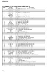
...2.2K 5% 1/10W 5% 1/10W 5% 1/10W 5% 1/10W 5% 1/10W Ref. No. No. Part No. Description Remark TM604 1-780-214-11 TERMINAL BOARD (SP) (2P) (SPEAKERS CENTER) POWER KEY BOARD < CONNECTOR > * CN103 1-691-670-11 CONNECTOR, BOARD TO BOARD 5P < RESISTOR > R111 1-249-415-11 CARBON 680 5% 1/4W < SWITCH > S100... PIN) (4P) (SPEAKERS FRONT B) D923 6-500-522-11 DIODE 10EDB40-TA2B5 < GROUND TERMINAL > G901 1-537-738-21 TERMINAL, GROUND 69 R758 R759 R760 R761 R763 R764 R765 R766 R767 R768 R769 R770 R771 R772 R773 R775 R778 R780 R790 R791 Part No. STR-K7100 MAIN POWER KEY STANDBY ...
...2.2K 5% 1/10W 5% 1/10W 5% 1/10W 5% 1/10W 5% 1/10W Ref. No. No. Part No. Description Remark TM604 1-780-214-11 TERMINAL BOARD (SP) (2P) (SPEAKERS CENTER) POWER KEY BOARD < CONNECTOR > * CN103 1-691-670-11 CONNECTOR, BOARD TO BOARD 5P < RESISTOR > R111 1-249-415-11 CARBON 680 5% 1/4W < SWITCH > S100... PIN) (4P) (SPEAKERS FRONT B) D923 6-500-522-11 DIODE 10EDB40-TA2B5 < GROUND TERMINAL > G901 1-537-738-21 TERMINAL, GROUND 69 R758 R759 R760 R761 R763 R764 R765 R766 R767 R768 R769 R770 R771 R772 R773 R775 R778 R780 R790 R791 Part No. STR-K7100 MAIN POWER KEY STANDBY ...


